-
Start Preamble
Start Printed Page 89806
AGENCY:
Office of Energy Efficiency and Renewable Energy, Department of Energy.
ACTION:
Final rule.
SUMMARY:
The U.S. Department of Energy (DOE) is revising its battery charger test procedure established under the Energy Policy and Conservation Act of 1975, as amended. These revisions will add a discrete test procedure for uninterruptible power supplies (UPSs) to the current battery charger test procedure.
DATES:
The effective date of this rule is January 11, 2017. The final rule changes will be mandatory for representations starting June 12, 2017. The incorporation by reference of certain publications listed in this rule is approved by the Director of the Federal Register on January 11, 2017.
ADDRESSES:
The docket, which includes Federal Register notices, public meeting attendee lists and transcripts, comments, and other supporting documents/materials, is available for review at www.regulations.gov. All documents in the docket are listed in the www.regulations.gov index. However, some documents listed in the index, such as those containing information that is exempt from public disclosure, may not be publicly available.
A link to the docket Web page can be found at https://www.regulations.gov/docket?D=EERE-2016-BT-TP-0018. The docket Web page will contain simple instructions on how to access all documents, including public comments, in the docket.
For further information on how to review the docket, contact the Appliance and Equipment Standards Program staff at (202) 586-6636 or by email: ApplianceStandardsQuestions@ee.doe.gov.
Start Further InfoFOR FURTHER INFORMATION CONTACT:
Jeremy Dommu, U.S. Department of Energy, Office of Energy Efficiency and Renewable Energy, Building Technologies Office, EE-5B, 1000 Independence Avenue SW., Washington, DC 20585-0121. Telephone: (202) 586-9870. Email: ApplianceStandardsQuestions@ee.doe.gov.
Pete Cochran, U.S. Department of Energy, Office of the General Counsel, GC-71, 1000 Independence Avenue SW., Washington, DC 20585-0121. Telephone: (202) 586-9496. Email: Peter.Cochran@hq.doe.gov.
End Further Info End Preamble Start Supplemental InformationSUPPLEMENTARY INFORMATION:
This final rule incorporates by reference the following industry standards into 10 CFR part 430:
1. ANSI/NEMA WD 6-2016, “Wiring Devices—Dimensional Specifications”, ANSI approved February 11, 2016, Figure 1-15 and Figure 5-15.
Copies of ANSI/NEMA WD 6-2016 can be obtained from American National Standards Institute, 25 W. 43rd Street, 4th Floor, New York, NY 10036, 212-642-4900, or by going to http://www.ansi.org
2. IEC 62040-3, “Uninterruptible power systems (UPS)—Part 3: Methods of specifying the performance and test requirements,” Edition 2.0, 2011-03, Section 5.2.1, Clause 5.2.2.k, Clause 5.3.2.d, Clause 5.3.2.e, Section 5.3.4, Section 6.2.2.7, Section 6.4.1 (except 6.4.1.3, 6.4.1.4, 6.4.1.5, 6.4.1.6, 6.4.1.7, 6.4.1.8, 6.4.1.9 and 6.4.1.10), Annex G, and Annex J.
Copies of the IEC 62040-3 Ed. 2.0 standard are available from the American National Standards Institute, 25 W. 43rd Street, 4th Floor, New York, NY 10036, or at http://webstore.ansi.org/.
For further discussion of these standards, see section IV.N.
Table of Contents
I. Authority and Background
II. Synopsis of the Final Rule
III. Discussion
A. Covered Products and Scope
B. Existing Test Procedures and Standards Incorporated by Reference
C. Definitions
1. Reference Test Load
2. Uninterruptible Power Supply
3. Input Dependency
4. Normal Mode
D. Test Conditions
1. Accuracy and Precision of Measuring Equipment
2. Environmental Conditions
3. Input Voltage and Frequency
E. Battery Configuration
F. Product Configuration
G. Average Power and Efficiency Calculation
1. Average Power
2. Efficiency
H. Output Metric
I. Effective Date of and Compliance With Test Procedure
J. Sampling Plan for Determination of Certified Rating
K. Certification Reports
L. Sample Represented Value Derivation
IV. Procedural Issues and Regulatory Review
A. Review Under Executive Order 12866
B. Review Under the Regulatory Flexibility Act
C. Review Under the Paperwork Reduction Act of 1995
D. Review Under the National Environmental Policy Act of 1969
E. Review Under Executive Order 13132
F. Review Under Executive Order 12988
G. Review Under the Unfunded Mandates Reform Act of 1995
H. Review Under the Treasury and General Government Appropriations Act, 1999
I. Review Under Executive Order 12630
J. Review Under Treasury and General Government Appropriations Act, 2001
K. Review Under Executive Order 13211
L. Review Under Section 32 of the Federal Energy Administration Act of 1974
M. Congressional Notification
N. Description of Materials Incorporated by Reference
V. Approval of the Office of the Secretary
I. Authority and Background
Title III of the Energy Policy and Conservation Act of 1975 (42 U.S.C. 6291, et seq.; “EPCA” or, “the Act”) sets forth a variety of provisions designed to improve energy efficiency.[1] Part B [2] of title III, established the Energy Conservation Program for Consumer Products Other Than Automobiles. Battery chargers are among the consumer products affected by these provisions. (42 U.S.C. 6295(u))
Under EPCA, the energy conservation program consists essentially of four parts: (1) Testing, (2) labeling, (3) federal energy conservation standards, and (4) certification and enforcement procedures. The testing requirements consist of test procedures that manufacturers of covered products must use as the basis for (1) certifying to DOE that their products comply with the applicable energy conservation standards adopted under EPCA, and (2) making representations about the efficiency of those products. Similarly, DOE must use these test procedures to determine whether the products comply with any relevant standards promulgated under EPCA.
General Test Procedure Rulemaking Process
Under 42 U.S.C. 6293, EPCA sets forth the criteria and procedures DOE must follow when prescribing or amending test procedures for covered products. EPCA provides in relevant part that any test procedures prescribed or amended under this section shall be reasonably designed to produce test results which Start Printed Page 89807measure energy efficiency, energy use or estimated annual operating cost of a covered product during a representative average use cycle or period of use and shall not be unduly burdensome to conduct. (42 U.S.C. 6293(b)(3))
In addition, if DOE determines that a test procedure amendment is warranted, it must publish proposed test procedures and offer the public an opportunity to present oral and written comments on them. (42 U.S.C. 6293(b)(2)) Finally, in any rulemaking to amend a test procedure, DOE must determine to what extent, if any, the proposed test procedure would alter the measured energy efficiency of any covered product as determined under the existing test procedure. (42 U.S.C. 6293(e)(1))
Background
DOE previously published a notice of proposed rulemaking (NOPR) on March 27, 2012, regarding energy conservation standards for battery chargers and external power supplies (March 2012 NOPR) in which it proposed standards for battery chargers, including uninterruptible power supplies (UPSs). 77 FR 18478.
Following the publication of this March 2012 NOPR, DOE explored whether to regulate UPSs as “computer systems.” See, e.g., 79 FR 11345 (Feb. 28, 2014) (proposed coverage determination); 79 FR 41656 (July 17, 2014) (computer systems framework document). DOE received a number of comments in response to those documents (and the related public meetings) regarding testing of UPSs, which are discussed in the May 2016 NOPR. DOE also received questions and requests for clarification regarding the testing, rating, and classification of battery chargers.
As part of the continuing effort to establish federal energy conservation standards for battery chargers and to develop a clear and widely applicable test procedure, DOE published a notice of data availability (May 2014 NODA) on May 15, 2014. 79 FR 27774. This NODA sought comments from stakeholders concerning the repeatability of the test procedure when testing battery chargers with several consumer configurations, and concerning the future market penetration of new battery charging technologies that may require revisions to the battery charger test procedure. DOE also sought comments on the reporting requirements for manufacturers attempting to comply with the California Energy Commission's (CEC's) efficiency standards for battery chargers in order to understand certain data discrepancies in the CEC database. These issues were discussed during DOE's May 2014 NODA public meeting on June 3, 2014.
Based upon discussions from the May 2014 NODA public meeting and written comments submitted by various stakeholders, DOE published a NOPR (August 2015 NOPR) to revise the current battery charger test procedure. 80 FR 46855 (Aug. 6, 2015). DOE received a number of stakeholder comments on the August 2015 NOPR and the computer systems framework document regarding regulation of battery chargers including UPSs. After considering these comments, DOE reconsidered its position and found that because a UPS meets the definition of a battery charger, it is more appropriate to regulate UPSs as part of the battery charger rulemaking. Therefore, DOE issued the May 2016 NOPR, which proposed to add a discrete test procedure for UPS to the existing battery charger test procedure. This final rule adopts the proposals discussed in the May 2016 NOPR, along with revisions suggested by stakeholder comments.
II. Synopsis of the Final Rule
This final rule adds provisions for testing UPSs to the battery charger test procedure. Specifically, DOE is incorporating by reference specific sections of the IEC 62040-3 Ed. 2.0 standard, with additional instructions, into the current battery charger test procedure published at appendix Y to subpart B of 10 CFR part 430. This final rule also adds formal definitions of uninterruptible power supply, voltage and frequency dependent UPS, voltage independent UPS, voltage and frequency independent UPS, energy storage system, normal mode and reference test load to appendix Y to subpart B of 10 CFR part 430 and revises the compliance certification requirements for battery chargers published at 10 CFR 429.39. Table II.1 shows the significant changes since the May 2016 NOPR.
Table II.1—Summary of Significant Changes
Sections May 2016 NOPR Final rule 429.39 • Proposed a sampling plan for compliance certification based on the test results of at least 2 units per basic model • Adopted the proposed sampling plan for compliance certification based on the test results of at least 2 units per basic model. Also added option for manufacturers to certify compliance based on the test results of a single unit per basic model. 1. Scope • Proposed scope covered all products that met the proposed definition of a UPS and have an AC output • Adopted scope covers all products that meet the adopted definition of UPS, utilize a NEMA 1-15P or 5-15P input plug and have an AC output. 2. Definitions • “Voltage and frequency independent UPS or VFI UPS means a UPS where the device remains in normal mode producing an AC output voltage and frequency that is independent of input voltage and frequency variations and protects the load against adverse effects from such variations without depleting the stored energy source. The input voltage and frequency variations through which the UPS must remain in normal mode is as follows: • “Voltage and frequency independent UPS or VFI UPS means a UPS where the device remains in normal mode producing an AC output voltage and frequency that is independent of input voltage and frequency variations and protects the load against adverse effects from such variations without depleting the stored energy source.” (1) ± 10% of the rated input voltage or the tolerance range specified by the manufacturer, whichever is greater; and (2) ± 2% of the rated input frequency or the tolerance range specified by the manufacturer, whichever is greater.” Start Printed Page 89808 • “Voltage independent UPS or VI UPS means a UPS that produces an AC output within a specific tolerance band that is independent of under-voltage or over-voltage variations in the input voltage without depleting the stored energy source. The output frequency of a VI UPS is dependent on the input frequency, similar to a voltage and frequency dependent system.” • “Voltage independent UPS or VI UPS means a UPS that produces an AC output within a specific tolerance band that is independent of under-voltage or over-voltage variations in the input voltage. The output frequency of a VI UPS is dependent on the input frequency, similar to a voltage and frequency dependent system.” 4. Testing Requirements for Uninterruptible Power Supplies • Proposed that the average power can be calculated either using accumulated energy or instantaneous power • Adopted that the average power can only be calculated using instantaneous power. • Proposed that efficiency can only be calculated from average power • Adopted that efficiency can be calculated from average power or accumulated energy. III. Discussion
In response to the May 2016 NOPR, DOE received written comments from six interested parties, including manufacturers, trade associations, energy efficiency advocacy groups, and a foreign government.
Table III.1 lists the entities that commented on the May 2016 NOPR and their affiliation. These comments are discussed in further detail below, and the full set of comments can be found at: https://www.regulations.gov/docketBrowser?rpp=25&so=DESC&sb=commentDueDate&po=0&dct=PS&D=EERE-2016-BT-TP-0018
Table III.1—Interested Parties That Provided Written Comments on the May 2016 NOPR
Commenter Acronym Organization type/affiliation Comment No. (docket reference) ARRIS Group, Inc ARRIS Manufacturer 0004 Information Technology Industry Council ITI Trade Association 0007 National Electrical Manufacturers Association NEMA Trade Association 0008 Natural Resources Defense Council, Appliance Standards Awareness Project, Northwest Energy Efficiency Alliance, Alliance to Save Energy, and American Council for an Energy Efficient Economy NRDC, et al. Energy Efficiency Advocates 0006 People's Republic of China P. R. China Foreign Government 0009 Schneider Electric Schneider Electric Manufacturer 0005 A number of interested parties also provided oral comments at the June 9, 2016, public meeting. These comments can be found in the public meeting transcript (Pub. Mtg. Tr.), which is available on the docket.
A. Covered Products and Scope
In the May 2016 NOPR, DOE proposed that all products that meet the proposed definition of UPS and have an AC output will be subject to the testing requirements of the proposed test procedure. 81 FR 31545. During the public meeting held on June 9, 2016, to discuss the May 2016 NOPR, Schneider Electric called the proposed scope broad and argued that the proposed scope covers UPSs that can operate at power levels beyond the standard household power plugs. (Schneider Electric, Pub. Mtg. Tr., No. 0003, EERE-2016-BT-TP-0018, pp. 16-17) Schneider Electric claimed that voltage and frequency dependent (VFD) UPSs exist in a consumer environment, voltage independent (VI) UPSs may exist in a consumer environment and voltage and frequency independent (VFI) UPSs do not exist in a consumer environment and requested that DOE update the proposed scope of the test procedure to represent what consumers are purchasing. (Schneider Electric, Pub. Mtg. Tr., No. 0003, EERE-2016-BT-TP-0018, pp. 29-30) NEMA requested that DOE adopt the standard wall plug requirement (12A at 115V) in the scope to differentiate consumer UPSs from commercial UPSs. (NEMA, Pub. Mtg. Tr., No. 0003, EERE-2016-BT-TP-0018, p. 22) Further, as part of written stakeholder comments, Schneider Electric expressed concern that DOE's definition of consumer products is inadequate to describe the scope of products that DOE intends to regulate. The range of products within the scope of the definition of consumer products will be much broader than consumer products in the marketplace and will include commercial and industrial applications that are not found in residences due to size and other criteria. (Schneider Electric, No. 0005, EERE-2016-BT-TP-0018, p. 1) Schneider Electric requested that DOE identify and add indicators to differentiate consumer products from commercial products, such as pluggable Type A equipment as defined by the IEC 60950-1 standard, to the scope. It reasoned that assumptions regarding covered versus non-covered products can result in significant effort and expense wasted redesigning non-covered products or result in significant fines for failing to redesign products mistakenly and unintentionally thought to be out of scope. Schneider Electric requested that DOE add the North American residential mains power, single phase requirement of no more than 12A to the scope and remove all rack mounted or rack mountable UPSs and UPSs that require multiphase power from the scope. (Schneider Electric, No. 0005, EERE-2016-BT-TP-0018, p. 5) Schneider Electric further pointed out that the proposed load weightings table refers to UPSs with output powers greater than 1500W, which could include UPSs that are not specifically targeted for consumers. According to Schneider Electric, UPSs greater than Start Printed Page 898091500W are consistently targeted at commercial and industrial applications and DOE's attempt to regulate them is not justified by the scope of EPCA or the Energy Independence and Security Act of 2007 (EISA). Schneider Electric explained that the proposed scope can cause UPSs that are not intended to be distributed to consumer or in residential applications to be included within the scope of the test procedure, inflating savings for the DOE that are clearly not consumer based. In addition, this causes undue burden on the industry to test devices which were not intended for consumer applications, but may fall within the scope. (Schneider Electric, No. 0005, EERE-2016-BT-TP-0018, p. 8) NEMA requested that DOE narrow the scope of the proposed test procedure by adding the following parameters: non-rack mounted, FCC Class B compliant, 12A at 120 V or less, whose input characteristics are either VFD or VI. NEMA argued that products outside these parameters are commercial in nature or have power consumption and electrical characteristics which place them outside the use in typical consumer environments. (NEMA, No. 0008, EERE-2016-BT-TP-0018, p. 4)
DOE had also solicited comments from stakeholders on the use of product characteristics, such as capacity, to narrow the scope of coverage and differentiate between consumer and commercial UPSs in the computer and battery backup systems framework document published on July 11, 2014 where DOE explored whether to regulate UPSs as part of that rulemaking. ITI noted that personal computers are powered using single residential/office outlet, 5-15 amperes (A) typically. (ITI, No. 0010, EERE-2014-BT-STD-0025, p. 2) ITI also commented that UPSs at home do not utilize multiphase voltage and the maximum amperage of a single device on a single branch circuit should be less than or equal to 80 percent of the circuit amperage the limit for which is 15A according to the National Electrical Code (NEC). (ITI, No. 0010, EERE-2014-BT-STD-0025, p. 11). Schneider Electric noted that run-time and battery capacity of the UPS would be inappropriate as a differentiator since commercial and consumer customers may have similar needs but that consumer (residential) applications do not exist in excess of 120V and that the NEC defines residential circuitry amperage limit for a single branch to be 15 Amps. (Schneider Electric, No 0008, EERE-2014-BT-STD-0025, p. 8). The Natural Resources Defense Council (NRDC), The Appliance Standard Awareness Project (ASAP), American Council for an Energy-Efficient Economy (ACEEE), Consumer Federation of America, Consumers Union, Northeast Energy Efficiency Partnerships (NEEP), and Northwest Energy Efficiency Alliance (NEEA) (hereafter referred to as Joint Responders) also agreed with the use of residential power circuits for differentiating consumer from commercial UPSs, but discouraged the use of a standard wall plug as it would eliminate UPSs capable of running on 240V 3-phase receptacles. (Joint Responders, No. 0013, EERE-2014-BT-STD-0025, p. 6)
In response to Schneider Electric's comment regarding the definition of consumer product, DOE notes that the definition of this term in 10 CFR 430.2 is the same as that set forth by Congress in EPCA. (42 U.S.C. 6291(1)) Further, in the May 2016 NOPR, DOE found that UPSs meet the definition of battery charger and proposed to define UPS as “a battery charger consisting of a combination of convertors, switches and energy storage devices, constituting a power system for maintaining continuity of load power in case of input power failure.” Battery chargers are a type of consumer product, defined in EPCA, for which the statute directs DOE to prescribe test procedures. (42 U.S.C. 6295(u)) Therefore, necessarily, the scope of the battery charger test procedure, which includes UPSs, only applies to consumer products.
Nonetheless, after considering stakeholder comments regarding the proposed scope, DOE agrees with NEMA, ITI and Schneider Electric's suggestion that the scope of the test procedure need not include products typically used in a commercial or industrial environment. Accordingly, DOE is limiting the scope of the test procedure to UPSs that utilize a standard NEMA 1-15P and 5-15P wall plugs. NEMA 1-15P and 5-15P input plugs are designed to mate with NEMA 1-15R and 5-15R receptacles as specified in ANSI/NEMA WD 6-2016. These receptacles are the most commonly found outlets in U.S. households with limited use in products designed to exclusively operate in commercial or industrial environments because of their restrictive power handling capability. Specifying NEMA 1-15P and 5-15P plugs in defining the scope of this test procedure also avoids the need for DOE to further add power constraints as these plugs are only capable of handling up to 15A of current at 125V, which limits their maximum power handling capability to 1875W. DOE is therefore adding the NEMA 1-15P and 5-15P input plug requirement by incorporating by reference ANSI/NEMA WD 6-2016 standard into section 1, “Scope”, of appendix Y to subpart B of 10 CFR part 430. Hence, any product that meets the definition of a UPS, utilizes a NEMA 1-15P or 5-15P input plug, and has an AC output is covered under the testing requirements being adopted in this final rule.
Schneider Electric also inquired whether specific or all DC output UPSs are excluded from the proposed scope of the test procedure, and if the proposed scope includes hybrid AC/DC UPSs, UPSs with DC charging, and UPSs with USB ports. (Schneider Electric, Pub. Mtg. Tr., No. 0003, EERE-2016-BT-TP-0018, pp. 16-17, 20) (Schneider Electric, No. 0005, EERE-2016-BT-TP-0018, p. 6) Schneider Electric also requested clarification on whether UPSs that do not have an AC output socket or UPSs that do not provide the full power rating through the AC output socket are excluded from the proposed scope. (Schneider Electric, Pub. Mtg. Tr., No. 0003, EERE-2016-BT-TP-0018, p. 32) Lastly, Schneider Electric inquired whether the USB ports of a UPS be loaded or unloaded during testing. (Schneider Electric, Pub. Mtg. Tr., No. 0003, EERE-2016-BT-TP-0018, p. 20)
DOE clarifies that all products that meet the definition of UPS, utilize a NEMA 1-15P or 5-15P input plug, and have AC output(s) are included in scope under the testing requirements of this final rule. This includes UPSs with AC output(s) as well as additional DC output(s) such as but not limited to USB port(s). Similarly, hybrid AC/DC output UPSs are also included in scope under the testing requirements of this final rule. All DC output port(s) of an AC output UPS must be unloaded during testing. DOE is adding specific language in section 4.2.1, which is being added to appendix Y to subpart B of 10 CFR part 430 to highlight this setup requirement. Further, it is DOE's understanding and intention that the term “AC output socket” of a UPS refers to any port capable of providing the full or partial rated output power of the UPS as AC. The scope is not limited to UPSs with standardized NEMA receptacles. Therefore, all UPSs that utilize NEMA 1-15P or 5-15P input plugs and have an AC output are included in the scope of this final rule.
Schneider Electric also inquired if UPSs with ultra-capacitors, flywheels and storage technologies other than batteries are covered under the proposed scope. (Schneider Electric, Pub. Mtg. Tr., No. 0003, EERE-2016-BT-TP-0018, p. 31) DOE notes that UPSs are a subset of battery chargers. A Start Printed Page 89810product that does not meet the definition of a battery charger as stated in 10 CFR 430.2 is excluded from the scope of the UPS test procedure being adopted today. Because ultra-capacitor, flywheels, or storage technologies other than batteries do not meet the definition of a battery as stated in section 2.6 of appendix Y to subpart B of 10 CFR part 430, DOE concludes that UPSs that use ultra-capacitor, flywheels, or storage technologies other than batteries as their energy storage system also do not meet the definition of battery charger and therefore are excluded from the scope of the UPS test procedure.
ARRIS submitted written comments arguing that products such as modems that use a battery exclusively for back-up power have architectures that would fit within the standard IEC 62040-3 Ed. 2.0 definition of a UPS which states that “uninterruptible power supply or UPS means a combination of convertors, switches and energy storage devices (such as batteries), constituting a power system for maintaining continuity of load power in case of input power failure”. ARRIS highlighted that a simple addition to this definition to reflect that the load power is provided to external devices would provide clarity and help differentiate covered UPSs from other products with a battery exclusively for back-up purposes, which only provide continuity of power internally to the product. (ARRIS, No. 0004, EERE-2016-BT-TP-0018, pp. 2-3) Lastly, ARRIS highlighted that considering a product's typical use also helps differentiate UPS products that provide AC output from other products with a back-up battery that have typical uses such as lighting, medical, security, networking equipment, etc. (ARRIS, No. 0004, EERE-2016-BT-TP-0018, p. 4)
DOE agrees with ARRIS that the definition of a UPS may cover certain back-up battery chargers; however, the current battery charger test procedure specifically defines and excludes back-up battery chargers from its scope. Therefore, certain back-up battery chargers such as those found in cable modems that may meet the definition of a UPS will continue to be excluded from the battery charger test procedure. Additionally, DOE's proposed scope as stated in section 1 of appendix Y to subpart B of 10 CFR part 430 is limited to UPSs with an AC output. (81 FR 31554) Even if a back-up battery charger meets the definition of a UPS, DOE is not aware of any such back-up battery charger that has an AC output. Therefore limiting the scope to only UPSs with an AC output further prevents the applicability of this test procedure to the type of backup battery charger that is of concern to ARRIS. DOE also does not consider a product's typical use an effective way of prescribing the scope of a rulemaking as this leaves significant room for interpretation. With the added requirement of NEMA 1-15P and 5-15P input plugs, the adopted scope of UPS test procedure is definitive and unambiguous.
P. R. China highlighted that Appendix J.2 of IEC 62040-3 Ed. 2.0 standard does not apply to products with output power of less than or equal to 0.3 kilo Volt-Amperes (kVa) and requested DOE to make the proposed test method consistent with the IEC 62040-3 Ed. 2.0 standard by excluding UPSs with output power of less than or equal to 0.3 kVa. (P. R. China, No. 0009, EERE-2016-BT-TP-0018, p. 3) While Annex I of the IEC 62040-3 Ed. 2.0 standard prescribes efficiencies for UPSs rated above 0.3 kVA, the actual conditions and methods for determining the efficiency of a UPS stated in Annex J of the IEC 62040-3 Ed. 2.0 standard does not have any scope restrictions as claimed by P. R. China and are applicable to UPSs rated below 0.3 kVA. Additionally, DOE does not have any data to indicate that UPSs with output power of less than or equal to 0.3 kVA are any different in design than those above 0.3kVA such that this test method would not accurately capture their energy performance. Therefore, DOE is not excluding UPSs with output power of less than or equal to 0.3 kVA from the scope of the UPS test procedure.
B. Existing Test Procedures and Standards Incorporated by Reference
In the May 2016 NOPR, DOE proposed to add specific testing provisions for UPSs in the battery charger test procedure, because the specifications in the current battery charger test procedure are not appropriate for UPSs. The current battery charger test procedure measures energy consumption of a battery charger as it charges a fully discharged battery, which is inappropriate for a UPS because a UPS rarely has a fully discharged battery. The majority of the time a UPS provides a small amount of charge necessary to maintain fully charged batteries and also delivers power to a connected load. Therefore, in order to accurately capture the energy consumption and energy efficiency of the normal operation of a UPS, the test procedure should measure the energy consumption of maintaining a fully charged battery and conversion losses associated with delivering load power. 81 FR 31545.
Schneider Electric appreciated that DOE has agreed with and supports the industry's position that UPSs operate differently than most battery chargers. (Schneider Electric, No. 0005, EERE-2016-BT-TP-0018, p. 2) NEMA agreed with the establishment of a test procedure for UPSs, consistent with NEMA's comments cited by DOE in the May 2016 NOPR. (NEMA, No. 0008, EERE-2016-BT-TP-0018, p. 3) NEMA also agreed with DOE's conclusion that measuring the energy use of a UPS in normal mode effectively captures the energy used during the entirety of the time that a UPS is connected to mains power. (NEMA, No. 0008, EERE-2016-BT-TP-0018, p. 6) Further, ARRIS also supported DOE's conclusion that the current battery charger test procedure does not represent typical use of a UPS and reiterated that the current battery charger test procedure does not work well for continuous use products that include a battery exclusively for back-up purposes. (ARRIS, No. 0004, EERE-2016-BT-TP-0018, p. 3)
To measure the energy consumption of a UPS during normal mode, DOE proposed to incorporate by reference Section 6 and Annex J of IEC 62040-3 Ed. 2.0 in the battery charger test procedure. 81 FR 31546.
Schneider Electric supported incorporation by reference of the IEC 62040-3 Ed. 2.0 standard without DOE's proposed changes in the battery charger test procedure and provided an advanced notice that the IEC 62040-3 Ed. 2.0 standard is under maintenance and anticipated to be revised over the next 2 years. (Schneider Electric, No. 0005, EERE-2016-BT-TP-0018, p. 1) However, NEMA highlighted that there are presently no planned changes to the IEC 62040-3 Ed. 2.0 standard that would affect the manner in which a UPS is tested for efficiency. (NEMA, No. 0008, EERE-2016-BT-TP-0018, p. 3)
In light of these stakeholder comments, DOE is finalizing the incorporation by reference of Section 6 and Annex J of IEC 62040-3 Ed. 2.0 in the battery charger test procedure. Additionally, DOE will monitor the revision of the IEC 62040-3 standard and consider, once these revisions are complete, whether to initiate a new test procedure rulemaking to consider incorporating the latest version.
C. Definitions
In the May 2016 NOPR, DOE proposed to include the following definitions, in section 2 of appendix Y to subpart B of 10 CFR part 430. DOE requested stakeholder comments on all proposed definitions, which are discussed in the following subsections:Start Printed Page 89811
1. Reference Test Load
DOE proposed the following definition for reference test load: “Reference test load is a load or condition with a power factor of greater than 0.99 in which the AC output socket of the UPS delivers the active power (W) for which the UPS is rated.” 81 FR 31554. NRDC, et al. argued that a resistive reference test load (power factor greater than or equal to 0.99) may not be representative of common UPS applications such as desktop computers. NRDC, et al. provided data to show that the power factor of a non-ENERGY STAR desktop computer without power factor correcting functionality can be quite low and urged DOE to evaluate the potential differences in UPS efficiency when serving loads with different power factors including non-linear loads that are more representative of computers and other typical UPS applications. If the difference in measured efficiency between different load types is significant, NRDC, et al. requested that DOE specify a reference test load that is more representative of common applications, particularly for VFD UPS which commonly serve loads with low power factors. (NRDC, et al., No. 0006, EERE-2016-BT-TP-0018, p. 2-3)
The proposed power factor requirement of reference test load aligns with ENERGY STAR UPS V. 1.0 and the IEC 62040-3 Ed. 2.0 standard, which are extensively supported by the UPS industry. DOE is refraining from adopting a reference test load with a power factor that differs from that of ENERGY STAR UPS V. 1.0 or the IEC 62040-3 Ed. 2.0 because DOE does not have enough market information to assess the impact of such a divergence from ENERGY STAR UPS V. 1.0 and IEC 62040-3 Ed. 2.0. Therefore, DOE is adopting the proposed reference test load in this final rule. DOE will continue to monitor the UPS market and may consider adopting other reference test loads in future rulemakings.
2. Uninterruptible Power Supply
DOE proposed the following definition for UPS: “Uninterruptible power supply or UPS means a battery charger consisting of a combination of convertors, switches and energy storage devices, constituting a power system for maintaining continuity of load power in case of input power failure.” 81 FR 31554. Schneider Electric disagreed with the proposed definition of UPS. Schneider Electric argued that the proposed definition of UPS implies that the primary function of a UPS is to charge batteries, and asserted that the primary functions of a UPS are wave shaping, power conditioning, assuring the quality of power, measuring the quality of power on a continual basis, detecting mains power drop out, communicating the status, and reporting abnormal conditions through networked ports. Schneider Electric stated that UPSs only charge batteries intermittently and in some cases charge batteries after a few days or weeks. (Schneider Electric, Pub. Mtg. Tr., No. 0003, EERE-2016-BT-TP-0018, pp. 15-16; Schneider Electric, No. 0005, EERE-2016-BT-TP-0018, p. 3) Lastly, Schneider Electric argued that DOE's proposed definition of UPS may have major implications on the market and the product in the marketplace and requested that DOE adopt the definition of UPS from the IEC 62040-3 Ed. 2.0 standard. (Schneider Electric, No. 0005. EERE-2016-BT-TP-0018, p. 3; Schneider Electric, Pub. Mtg. Tr., No. 0003, EERE-2016-BT-TP-0018, p. 19) Similarly, NEMA requested that DOE adopt the definition of UPS from the established IEC 62040-3 Ed. 2.0 standard and highlighted that the Office of Management and Budget CircularA-119 encourages the use of international standards in establishing regulations when effective and appropriate in the fulfillment of legitimate objectives of the agency and the underlying statute. NEMA argued that these criteria are satisfied by using the definition of UPS in the IEC 62040-3 Ed. 2.0 standard and highlighted that the CSA C813.1 specification in Canada, and the European Norms reference the IEC 62040-3 Ed. 2.0 standard. NEMA contended that, as DOE attempts to harmonize its regulations with Canada and the European Union, deviation from the IEC 62040-3 Ed. 2.0 standard would make DOE's UPS regulations impossible to harmonize with international norms. (NEMA, No. 0008, EERE-2016-BT-TP-0018, pp. 2-4)
Schneider Electric acknowledged that a UPS system contains or has embedded within the UPS a battery charger. Further, Schneider does not question DOE's authority to regulate a UPS as a battery charger (Schneider Electric, No. 0005, EERE-2016-BT-TP-0018, p. 2). DOE notes that 10 CFR 430.2 defines a battery charger as a device that charges batteries for consumer products, including battery chargers embedded in other consumer products. It does not state or imply that the primary function of a product that meets the definition of battery charger is to charge batteries. UPSs charge and maintain their batteries at full charge and therefore meet the statutory definition of a battery charger. DOE disagrees with Schneider Electric's comment that the proposed definition of UPS implies that that the primary function of a UPS is to charge batteries and that the proposed UPS definition may have major implications on the market and the product in the marketplace. There is only one difference between the proposed DOE definition and IEC definition of a UPS and that is that DOE refers to UPSs as battery charger within the proposed definition. As DOE is regulating UPSs as part of its battery charger regulations, it is necessary to indicate in the UPS definition that UPSs are a subset of battery chargers, and, as a result, must also meet EPCA's definition of a battery charger. Accordingly, DOE is adopting the proposed definition of a UPS in this final rule.
3. Input Dependency
In the May 2016 NOPR, DOE proposed definitions for VFD UPS, VI UPS and VFI UPS in section 2 of appendix Y to subpart B of 10 CFR part 430. In this final rule, DOE is revising the proposed definition of VI UPS to highlight that a VI UPS, in normal mode, must not deplete its stored energy source when outputting an AC voltage within a specific tolerance band that is independent of under-voltage or over-voltage variations in the input voltage. This change brings consistency between the definitions of VI and VFI UPSs.
To help manufacturers determine whether a UPS is properly considered to be VFD, VI, or VFI, DOE also proposed tests to verify the input dependency of the UPS as follows: VI input dependency may be verified by performing the steady state input voltage tolerance test in section 6.4.1.1 of IEC 62040-3 Ed. 2.0 and observing that the output voltage remains within the specified limit during the test. VFD input dependency may be verified by performing the AC input failure test in section 6.2.2.7 of IEC 62040-3 Ed. 2.0 and observing that, at a minimum, the UPS switches from normal mode of operation to battery power while the input is interrupted. VFI input dependency may be verified by performing the steady state input voltage tolerance test and the input frequency tolerance test specified in sections 6.4.1.1 and 6.4.1.2 of IEC 62040-3 Ed. 2.0 and observing that, at a minimum, the output voltage and frequency remain within the specified output tolerance band during the test. These tests may be performed to determine the input dependency supported by the test unit.
NEMA and Schneider Electric argued that UPS manufacturers already know the architecture of their models and Start Printed Page 89812DOE's proposed tests to identify the architecture of a UPS will unjustifiably increase testing burden for manufacturers. (NEMA, No. 0008, EERE-2016-BT-TP-0018, p. 4; Schneider Electric, No. 0005, EERE-2016-BT-TP-0018, p. 2) Schneider Electric requested DOE to exclude the proposed performance criteria from input dependency tests and, similar to the IEC 62040-3 Ed. 2.0 standard, rely on manufacturer declarations to classify UPSs as VFD, VI or VFI. (Schneider Electric, Pub. Mtg. Tr., No. 0003, EERE-2016-BT-TP-0018, pp. 32-33)
While most UPS manufacturers are aware of the input dependencies of their models, there are UPS models available in the marketplace whose input dependencies may not be obvious to a third party. In response to the comment from Schneider Electric and NEMA, DOE notes that the input dependency tests being adopted in sections 2.27.1, 2.27.2 and 2.27.3 of this final rule, are not mandatory. If a manufacturer is already aware that the basic model in question conforms to the performance criteria outlined in section 2.27.1, 2.27.2 and 2.27.3, the input dependency tests need not be performed. However, because these performance criteria are included within the definition of each UPS architecture, the onus is on the manufacturer to properly classify their UPS according to this criteria in order to represent its energy efficiency and adhere to any potential energy conservation standard.
With regards to performance criteria, Section 5.2.1 of the IEC 62040-3 Ed. 2.0 standard asks that the UPS must remain in normal mode when the input voltage and frequency is varied by ±10% and ±2%, respectively, for the IEC 62040-3 Ed. 2.0 standard to be applicable. Although the specific steady state input voltage and frequency tolerance tests of sections 6.4.1.1 and 6.4.1.2 of the IEC 62040-3 Ed. 2.0 standard require that the UPS need only meet the tolerance range specified by the manufacturer of the device, the requirements of section 5.2.1 must first be met at a minimum. In aligning its requirements with that of IEC 62040-3 Ed. 2.0, DOE has also used the criteria of section 5.2.1 of the IEC 62040-3 Ed. 2.0 standard in the definition of VI and VFI UPSs in this final rule. DOE notes that these adopted performance criteria will remove any ambiguity in the classification of UPS input dependency during certification and enforcement.
If manufacturers are uncertain about the input dependency of their UPS models, then manufacturers can perform the input dependency tests and use the associated performance criteria to verify the input dependency of their models. In enforcement testing, DOE will use these input dependency tests and performance criteria to verify the classification claimed by a manufacturer in the compliance certification report of a UPS basic model and to ensure that the correct load weightings, listed in table 4.3.1 of appendix Y to subpart B of 10 CFR part 430, were applied. This also ensures that manufacturers are not left to create their own performance criteria for VFD, VI and VFI classification, which would lead to inconsistencies in the certified results. Because section 4.3.4 of appendix Y to subpart B of 10 CFR part 430 is being made optional in this final rule, this rule also amends 10 CFR 429.134 to state that, in enforcement testing, DOE will determine the UPS architecture by performing the tests specified in the definitions of VI, VFD, and VFI in sections 2.28.1 through 2.28.3 of appendix Y to subpart B of 10 CFR part 430.
4. Normal Mode
In the May 2016 NOPR, DOE proposed a definition of normal mode in section 2 of appendix Y to subpart B of 10 CFR part 430. The proposed definition of normal mode required a UPS to provide output power to the connected load without switching to battery power. However, for VFI UPSs, the output power to the connected load may also be provided by the battery in normal mode of operation. Hence, the proposed definition of normal mode would have conflicted with the input dependency test for VFI UPSs. After careful consideration, DOE is revising the proposed definition of normal mode to specify that the AC input supply is within required tolerances and supplies the UPSs rather than that the UPS provides the required output power to the connected load without switching to battery power, and that the energy storage system is being maintained at full charge or is under charge rather than just being maintained at full charge. Further, the revision of the definition of normal mode increases harmonization between the definitions of normal mode in DOE's test procedure and the IEC 62040-3 Ed. 2.0 standard.
Additionally, DOE also proposed a definition for `Energy Storage Systems', on which DOE has not received any stakeholder comment; therefore DOE is adopting the proposed definition in this final rule.
D. Test Conditions
Although a majority of the test conditions proposed in the May 2016 NOPR were adopted from the IEC 62040-3 Ed 2.0 standard, DOE proposed certain supplementary instructions for the test conditions in appendix Y to subpart B of 10 CFR part 430 in order to eliminate the possibility of ambiguity. DOE requested comment on the proposed test conditions.
1. Accuracy and Precision of Measuring Equipment
DOE proposed that the power meter and other equipment used during the test procedure must provide true root mean square (r. m. s.) measurements of the active input and output power, with an uncertainty at full rated load of less than or equal to 0.5 percent at the 95 percent confidence level notwithstanding that voltage and current waveforms can include a harmonic component. Further, DOE proposed that the power meter and other equipment must measure input and output values simultaneously.
Schneider Electric argued that DOE's proposed accuracy and resolution requirements for UPSs are more stringent than those required to provide compliance test results. The proposed accuracy and measurement requirements would require manufacturers to test their units with more expensive test equipment, which would create an unjustified testing burden for UPS manufacturers. (Schneider Electric, No. 0005, EERE-2016-BT-TP-0018, p. 3) Schneider Electric further argued that the type and cost of the test equipment required to test UPS systems according to the proposed requirements will especially be burdensome on small and medium businesses. Schneider Electric contends that, although small and medium businesses can utilize third party test labs to mitigate the cost of purchasing test equipment, these businesses still need to purchase some test equipment to understand measurements of their products prior to submitting them for compliance testing, and that, the expense of using third party test labs or the test equipment required to meet the proposed accuracy and measurement requirements for compliance testing will reduce competition in the marketplace. (Schneider Electric, No. 0005, EERE-2016-BT-TP-0018, pp. 4-5)
DOE reiterates that the proposed accuracy and precision requirements for measuring equipment are adopted from section J.2.3 of the IEC 62040-3 Ed. 2.0 standard. It is DOE's understanding that the IEC 62040-3 Ed. 2.0 standard is widely accepted by the UPS industry. Therefore, DOE does not find that the proposed accuracy and precision requirements for measuring equipment are unjustified or burdensome for Start Printed Page 89813manufacturers. Hence, DOE is adopting the proposed accuracy and precision requirements in this final rule.
Schneider Electric argued that in case the manufacturer specified calibration interval of test equipment is longer than DOE's proposed calibration interval of 1 year, DOE's proposed calibration interval would be unjustifiably burdensome on manufacturers. (Schneider Electric, Pub. Mtg. Tr., No. 0003, EERE-2016-BT-TP-0018, pp. 36-37) After careful consideration, DOE agrees with Schneider Electric and is requiring all measurement equipment used to conduct tests must be calibrated within the equipment manufacturer's specified calibration period.
2. Environmental Conditions
IEC 62040-3 Ed 2.0 requires that the ambient temperature must be in the range of 20 °C to 30 °C. To ensure repeatability, DOE proposed to increase the precision required for ambient temperature measurements, while keeping the same range. As a result, the ambient temperature would be 20.0 °C to 30.0 °C (i.e., increasing the required precision by one decimal place) and the measurement would include all uncertainties and inaccuracies introduced by the temperature measuring equipment. Extending the precision of IEC's ambient temperature range requirement by one decimal place would minimize rounding errors and avoid scenarios in which a temperature of 19.6 °C would be rounded to 20 °C during testing and potentially provide higher efficiency usage values than those obtained at or above 20.0 °C. The proposal also required that the tests be carried out in a room with an air speed immediately surrounding the unit under test (UUT) of less than or equal to 0.5 meters per second (m/s). As proposed, there would be no intentional cooling of the UUT such as by use of separately powered fans, air conditioners, or heat sinks. The UUT would be tested on a thermally non-conductive surface.
Schneider Electric inquired whether manufacturers would be permitted to test UPSs within the temperature range specified by the IEC 62040-3 Ed. 2.0 standard. Schneider Electric also noted that the IEC 62040-3 Ed. 2.0 standard does not have air speed requirements, and inquired if DOE's proposed requirements for air speed surrounding the unit under test limit of less than or equal to 0.5 m/s would be unidirectional or multidirectional. (Schneider Electric, Pub. Mtg. Tr., No. 0003, EERE-2016-BT-TP-0018, pp. 36-38) Similarly, NEMA opposed DOE's proposed test conditions, such as airflow, and requested that DOE incorporate by reference the testing conditions stated in the IEC 62040-3 Ed. 2.0 standard. (NEMA, No. 0008, EERE-2016-BT-TP-0018, p. 5)
DOE reiterates that the May 2016 NOPR proposed the ambient temperature must remain in the range of 20.0 °C to 30.0 °C, including all inaccuracies and uncertainties introduced by the temperature measurement equipment, throughout the test. 81 FR 31559. The IEC 62040-3 Ed. 2.0 standard requires the ambient temperature to be between 20 °C and 30 °C, does not require all inaccuracies and uncertainties introduced by the temperature measurement equipment to be included in this range, and it has a precision requirement that is lower by one decimal place. By testing within DOE's ambient temperature range, which includes all inaccuracies and uncertainties, manufacturers will also meet the temperature requirements of the IEC 62040-3 Ed. 2.0 standard. Therefore, DOE is adopting the proposed ambient temperature range in this final rule. Further, DOE is adopting an air speed requirement surrounding the unit under test to avoid the possibility of intentional cooling during testing, which affects the efficiency of UPSs. DOE clarifies that the air speed limit of less than or equal to 0.5 m/s surrounding the unit under test is multidirectional.
3. Input Voltage and Frequency
DOE proposed that the AC input voltage to the UUT be within 3 percent of the highest rated voltage and the frequency be within 1 percent of the highest rated frequency of the device. DOE has not received any stakeholder comments on the input voltage and frequency requirements; therefore, DOE is adopting the proposed input voltage and frequency requirements in this final rule.
E. Battery Configuration
To capture the complete picture of the energy performance of UPSs, DOE proposed to test UPSs with the energy storage system connected throughout the test. Additionally, DOE proposed to standardize battery charging requirements for UPSs by including specific instructions in section 4.2.1, which is being added to appendix Y to subpart B of 10 CFR part 430. These requirements, which ensure that the battery is fully charged prior to testing, specify charging the battery for an additional 5 hours after the UPS has indicated that it is fully charged, or if the product does not have a battery indicator but the user manual specifies a time, charging the battery for 5 hours longer than the manufacturer's estimate. Finally, the proposal required charging the battery for 24 hours if the UPS does not have an indicator or an estimated charging time. 81 FR 31559.
Schneider Electric argued that it is more appropriate to test UPSs either without batteries or when the attached batteries are not allowed to discharge. Further, Schneider Electric argued that the battery charger in a UPS is turned off when it is not actively charging a depleted battery and the battery doesn't consume significant energy during normal mode of operation; therefore, testing with batteries does not add much to the test results. (Schneider Electric, No. 0005, EERE-2016-BT-TP-0018, p. 6; Schneider Electric, Pub. Mtg. Tr., No. 0003, EERE-2016-BT-TP-0018, p. 77) Schneider Electric also pointed out that the ENERGY STAR test procedure does not include batteries, the IEC 62040-3 Ed. 2.0 standard allows UPSs to be tested with or without a battery, and the CEC test procedure tests UPSs with an attached battery, but manufacturers are allowed to disable all known battery charger functions. (Schneider Electric, Pub. Mtg. Tr., No. 0003, EERE-2016-BT-TP-0018, pp. 42-44) Similarly, ITI and NEMA opposed DOE's proposal of testing UPSs with a connected energy storage system and argued that testing a UPS with a battery will increase time and cost of the test and could possibly disqualify UPSs that are currently ENERGY STAR compliant. (ITI, No. 0007, EERE-2016-BT-TP-0018, p. 2; NEMA, No. 0008, EERE-2016-BT-TP-0018, p. 3) NEMA and Schneider Electric pointed out that testing a UPS with a fully charged battery, which is different from the ENERGY STAR and CEC test procedures, will render all data from the ENERGY STAR and CEC databases useless. (NEMA, No. 0008, EERE-2016-BT-TP-0018, pp. 3-4; Schneider Electric, No. 0005, EERE-2016-BT-TP-0018, pp. 2, 6-7) Further, NEMA and Schneider Electric argued that DOE's proposed test procedure significantly deviates from the ENERGY STAR test procedure and the IEC 62040-3 Ed. 2.0 standard and that DOE has not justified this deviation, which appears to be arbitrary and poses unjustified financial burden on manufacturers. (NEMA, No. 0008, EERE-2016-BT-TP-0018, p. 3; Schneider Electric, No. 0005, EERE-2016-BT-TP-0018, p. 9)
In addition to providing various types of power conditioning and monitoring functionality, depending on their architecture and input dependency, UPSs also maintain the fully-charged state of lead acid batteries with relatively high self-discharge rates so Start Printed Page 89814that in the event of a power outage, they are able to provide backup power instantly to the connected load. Maintaining the lead acid battery consumes energy which therefore directly affects a UPS's overall energy efficiency. To capture the typical use of a UPS as required by 42 U.S.C. 6293(b)(3), a UPS must be tested with the energy storage system connected throughout the test, so as to capture the energy spent by the UPS maintaining the lead acid battery. Hence, deviation from the ENERGY STAR and CEC test procedures is necessary and justified. Concerning the ENERGY STAR and CEC databases, DOE points out that the two mentioned databases are already non-compatible because of the differences in their respective test procedures.
Additionally, Schneider Electric noted that some UPSs turn off their battery chargers for days or weeks after detecting fully charged batteries and inquired if manufacturers are allowed to keep this behavior in place during testing. Schneider Electric further explained, when turned on, some UPSs perform a battery test that reduces the state of charge and lengthens the duration of time required to fully charge connected batteries. Therefore, Schneider Electric asked if manufacturers would be allowed to disable this feature to reduce the time and burden of testing. (Schneider Electric, Pub. Mtg. Tr., No. 0003, EERE-2016-BT-TP-0018, p. 41)
If a UPS, as supplied to an end user, automatically detects that the connected battery is fully charged and then disables its battery charging functionality, then this UPS will be tested as such, as it would be a proper representation of the product's typical energy use, which is a goal of all DOE test procedures. In response to Schneider Electric's second comment, manufacturers are not allowed to disable the feature that detects the state of charge and lengthens the duration of time required to fully charge connected batteries. Section 4.2.1(b), which was proposed and is being added to appendix Y to subpart B of 10 CFR part 430 in this final rule, instructs that the UPS must not be modified or adjusted to disable energy storage charging features, and the transfer of energy to and from the energy storage system must be minimized by ensuring the energy storage system is fully charged.
Lastly, Schneider Electric inquired whether the use of software battery charge indicators or some other industry standard practice is permitted; how test batteries should be selected if a UPS basic model can support multiple batteries; and how a basic model is to be selected if a UPS model has batteries supplied by multiple battery vendors. (Schneider Electric, Pub. Mtg. Tr., No. 0003, EERE-2016-BT-TP-0018, pp. 40-41) (Schneider Electric, Pub. Mtg. Tr., No. 0003, EERE-2016-BT-TP-0018, pp. 69-70)
Section 4.2.1(b)(1), which was proposed, and is being added to appendix Y to subpart B of 10 CFR part 430 in this final rule, provides instructions on how to determine when a UPS battery is fully charged. These instructions emphasize the use of a battery charge indicator which DOE interprets as either being physically on the device or a software that accompanies the UPS. Therefore, manufacturers may use software that acts as an indicator and communicates the battery's state of charge to the user if the software is packaged with the UPS. DOE is unable to provide instructions regarding the use of `other industry standard practices' as an indicator of a battery's state of charge without more details on these standard practices. Manufacturers must follow the instructions provided in section 4.2.1(b), which is being added to appendix Y to subpart B of 10 CFR part 430 to ensure that the batteries are fully charged prior to testing. DOE also recognizes that UPS may be capable of accommodating multiple battery models, battery vendors or battery capacities. Accordingly, it is possible that the efficiency of a UPS that otherwise has identical electrical characteristics would vary slightly based on the battery used. In the case in which a manufacturer uses different battery models, vendors or capacities in a single UPS, then the manufacturer may group some or all combinations of battery and UPS as part of a single UPS basic model and certifying compliance by ensuring that the represented efficiency of that UPS basic model applies to all combinations in the group. In that case, the represented efficiency should correspond to the least efficient combination in the group. If the Department selects a unit for assessment or enforcement testing, DOE may select any combination within the basic model to assess the entire basic model's compliance. Thus, if a manufacturer groups multiple battery and UPS combinations as part of a single basic model, DOE would test one combination to determine compliance pursuant to its regulations. Alternatively, the manufacturer may classify each unique UPSs configuration as separate basic models and certify each basic models individually. In the case where each unique UPS configuration is a separate basic model, DOE will test the unique UPS configuration to assess compliance.
F. Product Configuration
For configuring UPSs for testing, DOE proposed to reference Appendix J.2 of IEC 62040-3 Ed 2.0 in section 4.2.1, which would be added to appendix Y to subpart B of 10 CFR part 430. In addition to the IEC test method, DOE proposed to include additional requirements for UPS operating mode conditions and energy storage system derived from ENERGY STAR UPS V. 1.0. DOE did not consider including requirements for back-feeding, a condition in which voltage or energy available within a UPS is fed back to any of the input terminals of the UPS as specified in ENERGY STAR UPS V. 1.0 because back-feeding is generally only required for UPSs with an output power rating higher than loads commonly available in a consumer environment. Because the power range of UPSs in the scope of this rulemaking is limited by the requirement that these UPSs utilize a NEMA 1-15P or 5-15P plug, and loads in this range are readily available, DOE believes provisions for back-feeding will not be necessary. DOE has not received any stakeholder comment on these proposed provisions; therefore, DOE is adopting these provisions in this final rule.
On August 5, 2016, DOE published an energy conservation standards notice of proposed rulemaking for uninterruptible power supplies in the Federal Register (August 2016 NOPR). 81 FR 52196. In response to the August 2016 NOPR, NEMA and ITI, and Schneider Electric submitted written comments requesting that DOE thoroughly examine the impact of the energy consumption of secondary features such as USB charging ports, wired and wireless connectivity, displays, and communications etc. that are not related to battery charging on the proposed efficiency metric for UPSs. (NEMA and ITI, No. 0019, EERE-2016-BT-STD-0022 at p. 3; Schneider Electric, No. 0017, EERE-2016-BT-STD-0022 at pp. 1-2, 13) In response to the above summarized comments, DOE is adding language to the UPS test procedure, in section 4.2.2, stating that UPS manufacturers must disable features of the UPSs that do not contribute to the maintenance of fully charged battery or delivery of load power, so that the energy consumption of these features is not captured. This will permit manufacturers to disable these secondary features in order to reduce or eliminate the impact that the energy consumption of these features has on the measured efficiency metric.Start Printed Page 89815
In the case where a feature that does not contribute to the maintenance of fully charged battery(s) or delivery of load power cannot be turned off during testing and the UPS manufacturer believes that the test procedure evaluates the basic model in a manner that is not representative of its true energy characteristics as to provide materially inaccurate comparative data, DOE notes that there are provisions in place, as outlined in 10 CFR 430.27, for stakeholders to request a waiver or interim waiver from the test procedure. If such a waiver or interim waiver is granted, manufacturers are required to use an alternative test method to evaluate the performance of their product type in a manner that is representative of the energy consumption characteristics of the basic model.
Schneider Electric provided a list of secondary features along with the corresponding energy allowances that Schneider Electric believes should be made for these secondary features and proposed an alternate adjusted efficiency metric that accommodates the suggested allowances in place of the average load adjusted efficiency metric proposed by DOE in the May 2016 UPS test procedure NOPR. (Schneider Electric, No. 0017, EERE-2016-BT-STD-0022, pp. 1-2, 13). While DOE is not adopting Schneider Electric's proposed alternative calculation at this time, DOE notes that manufacturers may propose this as an alternative test procedure for consideration as part of a waiver petition.
G. Average Power and Efficiency Calculation
1. Average Power
DOE's proposal in the June 2016 NOPR required that all efficiency values be calculated from average power. DOE proposed two different methods for calculating average power so that manufacturers have the option of using a method better suited to the testing equipment already available at their disposal without having to purchase new equipment. DOE proposed to specify these calculation methods in section 4.3.1 of appendix Y to subpart B of 10 CFR part 430. The first proposed method of calculating average power is recording the accumulated energy (Ei) in kWh and then dividing accumulated energy (Ei) by the specified period for each test (Ti). For this method, the average power would be calculated using the following equation:

Additionally, DOE proposed a second method to calculate average power by sampling the power at a rate of at least one sample per second and computing the arithmetic mean of all samples over the time period specified for each test (Ti). For this method, the average power (Pavg) would be calculated using the following equation:

Where P i represents measured power during a single measurement (i), and n represents total number of measurements.
NEMA and Schneider Electric opposed DOE's proposal of two different methods of calculating average power and requested that DOE adopt the method of calculating average power stated in the IEC 62040-3 Ed. 2.0 standard. (NEMA, No. 0008. EERE-2016-BT-TP-0018, p. 5; Schneider Electric, No. 0005, EERE-2016-BT-TP-0018, p. 3) Schneider Electric inquired whether DOE has conducted an analysis to compare the accuracy of the two proposed methods (Schneider Electric, No. 0005, EERE-2016-BT-TP-0018, p. 4) Further, during the public meeting held on June 9, 2016, Schneider Electric requested that manufacturers be allowed to calculate efficiency directly from accumulated energy measurements without having to first calculate average power. (Schneider Electric, Pub. Mtg. Tr., No. 0003, EERE-2016-BT-TP-0018, p. 46)
DOE agrees, and is not adopting a requirement that average power be calculated as an intermediate step in order to calculate efficiency from accumulated energy measurements. Based on stakeholder comments, DOE is convinced that the intermediate step of converting energy measurements to average power is redundant.
The adopted method of calculating average power from instantaneous power measurements is still different from the method stated in the IEC 62040-3 Ed. 2.0 standard, which is requested by NEMA and Schneider Electric. DOE's adopted method requires measuring power for 15 minutes at a sampling rate of at least 1 sample per second, whereas the IEC 62040-3 Ed. 2.0 standard only requires three readings no more than 15 minutes apart, which lacks precision. DOE believes that measuring power for 15 minutes at a sampling rate of at least one sample per second is justified because it improves precision over the IEC 62040-3 Ed. 2.0 and does not pose a testing burden on manufacturers because measurement readings are taken and logged electronically. Further, the sampling rate of at least one sample per second ensures accuracy and repeatability of calculated values. Lastly, as DOE is no longer requiring the calculation of average power from accumulated energy measurements as part of the calculation of efficiency, Schneider Electric's comment regarding the comparison of the accuracy of the two proposed methods of calculating average power is no longer relevant to the methods adopted in this final rule. DOE is revising the proposed regulatory text in appendix Y to subpart B of 10 CFR part 430 to finalize these changes.
2. Efficiency
DOE proposed to calculate the efficiency of UPSs at each loading point as specified in section J.3 of IEC 62040-3 Ed 2.0. DOE also proposed additional requirements from ENERGY STAR UPS V. 1.0 for the purpose of ensuring repeatable and reproducible tests. ENERGY STAR UPS V. 1.0 specifies requirements for ensuring the unit is at steady state and calculating the efficiency measurements. The proposed requirements are included in section 4.3 of the proposed appendix Y to subpart B of 10 CFR part 430.
Schneider Electric argued that deviations in stability requirements and calculation of efficiency from the IEC 62040-3 Ed. 2.0 standard will increase testing burden on manufacturers by forcing them to test their products twice: Once under the IEC 62040-3 Ed. 2.0 standard and once under the DOE test method. (Schneider Electric, Pub. Mtg. Tr., No. 0003, EERE-2016-BT-TP-0018, p. 48) DOE notes that the IEC 62040-3 Ed. 2.0 standard uses temperature to determine stability but does not specify where the temperature measurements must be taken. This, in DOE's opinion, leaves room for interpretation and would cause reproducibility problems with the test procedure. The ENERGY STAR UPS Test Method Rev. May 2012, which partially relies on the IEC 62040-3 Ed. 2.0 standard, also recognizes this shortcoming in the IEC 62040-3 Ed. 2.0 standard and states its own stability requirements. Consequently, DOE is finalizing the stability requirements proposed in the May 2016 NOPR which have been adopted from the ENERGY STAR UPS Test Method Rev. May 2012, as these requirements are necessary for ensuring repeatability and reproducibility of measured values.Start Printed Page 89816
H. Output Metric
To capture the energy efficiency of a UPS, DOE proposed that the device be tested in normal mode. DOE further proposed to use an average load adjusted efficiency metric, rounded to one tenth of a percentage point, as the final output of the UPS test procedure.[3] DOE's proposed output metric for UPSs matches the output metric utilized by ENERGY STAR UPS V. 1.0. DOE also proposed to adopt the load weightings specified in ENERGY STAR UPS V. 1.0 for calculating average load adjusted efficiency of UPSs. These load weightings vary based on the ratio of the reference test load to the full rated load of the device, the UPS architecture and the output power rating of a UPS. The requirements for calculating the final metric, shown in Table III.2, were proposed to be incorporated in section 4.3.5 of appendix Y to subpart B of 10 CFR part 430. The proposed equation to calculate the average load adjusted efficiency of UPSs is as follows:
Effavg = (t25% × Eff|25%) + (t50% × Eff|50%) + (t75% × Eff|75%) + (t100% × Eff|100%)
Where:
Effavg = average load adjusted efficiency
tn% = proportion of time spent at the particular n% of the reference test load
Effn% = efficiency at the particular n% of the reference test load
Table III.2—UPS Load Weightings for Calculating Average Load Adjusted Efficiency
Rated output power (W) Input dependency characteristic Portion of time spent at reference load 25% 50% 75% 100% P ≤ 1500 W VFD 0.2 0.2 0.3 0.3 VI or VFI 0 0.3 0.4 0.3 P > 1500 W VFD, VI, or VFI 0 0.3 0.4 0.3 Schneider Electric inquired whether manufacturers are required to test UPSs at loading points that have zero weighting. Further, Schneider Electric requested that DOE mandate testing UPSs in order from 100 percent, 75 percent, 50 percent and 25 percent of the reference test load. (Schneider Electric, Pub. Mtg. Tr., No. 0003, EERE-2016-BT-TP-0018, pp. 50-51) In this final rule, DOE adds a footnote to Table 4.3.1 of section 4.3.5 of appendix Y to subpart B of 10 CFR part 430 stating that manufacturers do not have to test a UPS at the applicable loading point with zero weighting because the measured efficiency at this loading point does not contribute to the average load adjusted efficiency of the UPS. Further, in section 4.3.3(a) of appendix Y to subpart B of 10 CFR part 430, DOE already proposes to test UPSs in the order of 100 percent, 75 percent, 50 percent and 25 percent of the rated output power. Consistent with of Schneider Electric's comment about the order of testing, DOE is adopting the proposed order of testing in this final rule.
Additionally, NRDC, et al. argued that the proposed loading points are not representative of desktop computers attached to UPSs and that DOE should instead adopt 0 percent, 5 percent, 10 percent, 25 percent and 50 percent as loading points for VFD UPSs with 0.1, 0.3, 0.3, 0.15, 0.15 time weightings for their loading points respectively. Further, NRDC, et al. requested DOE to analyze and revise loading points and associated time weightings for VI and VFI UPSs as well. (NRDC, et al., No. 0006, EERE-2016-BT-TP-0018, pp. 3-6)
DOE's output metric, loading points and weightings are adopted from ENERGY STAR UPS V. 1.0, which is extensively supported and adhered to by the UPS industry. Further, the IEC 62040-3 Ed. 2.0 standard also uses the same loading points. DOE is refraining from adopting any loading points or weightings that differ from those in ENERGY STAR UPS V. 1.0 and IEC 62040-3 Ed. 2.0 as DOE has no data from which to conclude that it would be necessary to do so. Therefore, DOE is adopting the proposed output metric, loading points and weightings in this final rule. DOE will continue to monitor the UPS market and may consider other loading points and weightings in future rulemakings.
I. Effective Date of and Compliance With Test Procedure
EPCA prescribes that all representations of energy efficiency and energy use, including those made on marketing materials and product labels, must be made in accordance with DOE test procedures, beginning 180 days after publication of such a test procedure final rule in the Federal Register. (42 U.S.C. 6293(c)(2))
NEMA argued that DOE has not adequately investigated the number of stock keeping units (SKUs) involved in this rulemaking, and as such does not appear to understand the scope of impact and associated cost burden on manufacturers if they become required to retest all products, and revise markings and published performance information within 180 days. NEMA further argued that in addition to disqualifying currently ENERGY STAR compliant products, DOE's proposed test procedure will force ENERGY STAR to update its UPS specifications, with assistance from the industry, causing additional burden on industry resources and personnel. According to NEMA, these additional testing and requalification costs will not be trivial, because the U.S. Environmental Protection Agency (EPA) requires third party certification and testing at manufacturer's expense for its ENERGY STAR program. NEMA contends that, even if the EPA takes some time to update its specification, DOE's insistence on a 180-day implementation will negate this in practical terms, possibly forcing manufacturers to perform two tests and report two different efficiency levels in the near term, one to DOE and one to EPA. (NEMA, No. 0008, EERE-2016-BT-TP-0018, pp. 2-3) Similarly, Schneider Electric argued that manufacturers would have to re-test all ENERGY STAR-certified UPSs after DOE's UPS test procedure is finalized, and testing hundreds of basic UPS models in 180 days would not be practical. (Schneider Electric, Pub. Mtg. Tr., No. 0003, EERE-2016-BT-TP-0018, p. 69)
DOE acknowledges that for ENERGY STAR-certified basic models, further testing may be needed to make representations in accordance with the UPS test procedure. However, DOE has adopted NEMA and Schneider Electric's sampling plan to help minimize the burden by allowing a single unit sample as required by the current ENERGY Start Printed Page 89817STAR program. DOE will work closely with EPA if any transition is needed for the current ENERGY STAR UPS specification as a result of this final rule and will consult with manufacturers in accordance with the ENERGY STAR process.
As for the comments requesting additional time to translate current representations, DOE reiterates that EPCA mandates the date by which representations must be made in accordance with the DOE test procedure. Specifically with regard to NEMA's comment regarding reporting two different efficiency levels, DOE notes that EPCA does not permit this, instead requiring that all such representations be made in accordance with the DOE test procedure. (42 U.S.C. 6293(c)(2)) EPCA does provide an allowance for individual manufacturers to petition DOE for an extension of the 180-day period if the manufacturer may experience undue hardship in meeting the 180-day deadline. (42 U.S.C. 6293(c)(3)) To receive such an extension, petitions must be filed with DOE no later than 60 days before the end of the 180-day period and must detail how the manufacturer will experience undue hardship. (42 U.S.C. 6293(c)(3)) Beyond any such extension pursuant to the petition process specified by EPCA, as noted above, the statute does not permit DOE to extend the date by which representations must be made in accordance with the DOE test procedure.
J. Sampling Plan for Determination of Certified Rating
For any covered product, manufacturers are required to determine represented values, which includes certified ratings, for each basic model of a product, in accordance with the DOE test procedure. Because the proposed test procedure for UPSs and resulting metric differs from other battery chargers, DOE proposed that UPS manufacturers would certify the average load adjusted efficiency metric (Effavg) described in section III.H, as the representative value of energy efficiency for UPSs. To determine a rating for certifying compliance or making energy use representations, DOE typically requires manufacturers to test each basic model in accordance with the applicable DOE test procedure and apply the appropriate sampling plan. DOE proposed that the sampling provisions and certified rating requirements for battery chargers be applicable to UPSs, which requires a sample of at least 2 items to be tested.
Schneider Electric argued that testing at least two units of a basic model of UPS under the proposed test procedure will require more time and have a higher cost than testing a single unit according to the ENERGY STAR test procedure. They also argued that testing at least two units is unnecessarily burdensome on manufacturers and requested DOE to allow manufacturers to certify compliance of their basic models based on the test results of a single unit. (Schneider Electric, Pub. Mtg. Tr., No. 0003, EERE-2016-BT-TP-0018, pp. 53-55) Similarly, ITI and NEMA opposed DOE's proposal of testing at least two unit of a basic model of UPS to certify compliance. (ITI, No. 0007, EERE-2016-BT-TP-0018, p. 1, NEMA, No. 0008, EERE-2016-BT-TP-0018, p. 2)
After carefully considering the request by Schneider Electric, ITI and NEMA about certifying compliance based on the test results of a single unit per basic model of UPS, DOE is allowing all UPS manufacturers to certify compliance of their basic models based on either the general sampling plan stated in section (a)(4)(i) of 10 CFR 429.39 or on the test results of a single unit based on the sampling plan in section (a)(4)(ii) of 10 CFR 429.39. If manufacturers decide to certify compliance of a UPS basic model based on the test results of a single unit, the certified rating for this UPS basic model must be equal to the test results of the single unit tested. If a UPS manufacturer uses the general sampling plan stated in section (a)(4)(i) of 10 CFR 429.39 to certify compliance of a basic model, DOE will use the sampling plan for enforcement testing stated in appendix A to subpart C of 10 CFR part 429 for this basic model. If, however, a UPS manufacturer chooses to certify compliance of a basic model based on the test results of a single unit, then DOE will use a minimum sample size of one unit for enforcement testing and if a single unit in the sample of this UPS basic model does not meet the applicable Federal energy conservation standard, the UPS basic model will be considered non-compliant. DOE is revising 10 CFR 429.110 and adding appendix D to subpart C of 10 CFR part 429 to outline the sampling plans for enforcement testing of UPSs.
K. Certification Reports
In addition to the requirements specified in 10 CFR 429.12, which are applicable to each basic model of a covered product, DOE proposed the active power (W), apparent power (VA), rated input voltage (V), rated output voltage (V), efficiencies at 25 percent, 50 percent, 75 percent, and 100 percent, and average load adjusted efficiency of the UPS basic model be included in the battery charger certification report for UPSs in 10 CFR 429.39.
DOE has not received any stakeholder comments on the proposed certification report requirements; therefore, DOE is adopting the proposed certification report requirements in this final rule. Additionally, the section 4.2.1(a) of appendix Y to subpart B of 10 CFR part 430 will require that if a UPS can operate in two or more distinct normal modes as more than one UPS architecture, then the test shall be conducted in the lowest input dependency as well as the highest input dependency mode where VFD represents the lowest input dependency mode, followed by VI and then VFI. DOE is requiring that manufacturers report the input dependency modes and efficiencies at 25 percent, 50 percent, 75 percent, 100 percent and the average load adjusted efficiencies of the lowest and the highest input dependency modes as part of the battery charger certification reports for UPSs. DOE is revising the proposed language in 10 CFR 429.39 accordingly.
L. Sample Represented Value Derivation
Schneider Electric requested DOE to provide application notes or publications that show how to take actual measurement data and calculate represented values for UPSs. (Schneider Electric, Pub. Mtg. Tr., No. 0003, EERE-2016-BT-TP-0018, pp. 55-56) DOE is providing the following walkthrough to show how the represented value of the average load adjusted efficiency of a UPS basic model can be derived from the test results.
Given a 500W VFD UPS basic model, and following the requirements in 10 CFR 429.39, two units of this UPS basic model are tested to certify compliance. Testing two units of this hypothetical UPS basic model according to the provisions in appendix Y to subpart B of 10 CFR part 430 yields the following results:Start Printed Page 89818
Table III.3—Hypothetical Test Results of a 500W VFD UPS
Unit # 1 Unit # 2 Reference test load percentage Reference test load percentage 25% 50% 75% 100% 25% 50% 75% 100% Pavg_in (W) 80.2784 150.8857 220.7255 290.7188 80.2586 150.9758 220.7546 290.5996 Pavg_out (W) 69.9238 140.4241 209.9844 279.5877 69.9615 140.4254 209.9652 279.5695 Eff (%) 87.1016 93.0665 95.1337 96.1712 87.1701 93.0119 95.1125 96.2044 Using the average load adjusted equation in section 4.3.5 and the load weightings in Table 4.3.1 of appendix Y to subpart B of 10 CFR part 430, the average load adjusted efficiencies for the two test units are calculated.
Table III-4—Hypothetical Average Load Adjusted Efficiencies of the 500W VFD UPS
Unit # 1 Unit # 2 Average Load Adjusted Efficiency (%) 93.4251 93.4314 According to 10 CFR 429.39, the represented value of Effavg must be less than or equal to the lower of the mean of the sample, where:

and, x̄ is the sample mean; n is the number of samples; and xi is the Effavg of the i th sample; or, the lower 97.5-percent confidence limit (LCL) of the true mean divided by 0.95, where:
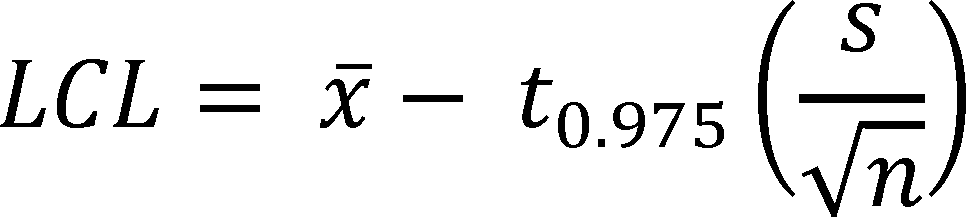
and x̄ is the sample mean; s is the sample standard deviation; n is the number of samples; and t0.975 is the t-statistic for a 97.5-percent one-tailed confidence interval with n-1 degrees of freedom (from appendix A of subpart B of 10 CFR part 429).
Following the stated equations, the mean of the sample and the 97.5-percent LCL divided by 0.95 are calculated.

Therefore, the represented value of the average load adjusted efficiency for the hypothetical 500W VFD UPS basic model must be less than 93.4 percent, the mean of the sample rounded to one-tenth of a percentage point, according to the rounding requirements specified in section 4.3.5(b) of appendix Y to subpart B of 10 CFR part 430.
IV. Procedural Issues and Regulatory Review
A. Review Under Executive Order 12866
The Office of Management and Budget has determined that test procedure rulemakings do not constitute “significant regulatory actions” under section 3(f) of Executive Order 12866, Regulatory Planning and Review, 58 FR 51735 (Oct. 4, 1993). Accordingly, this action was not subject to review under the Executive Order by the Office of Information and Regulatory Affairs (OIRA) in the Office of Management and Budget.
B. Review Under the Regulatory Flexibility Act
The Regulatory Flexibility Act (5 U.S.C. 601 et seq.) requires that when an agency promulgates a final rule under 5 U.S.C. 553, after being required by that section or any other law to publish a general notice of proposed rulemaking, the agency shall prepare a final regulatory flexibility analysis (FRFA). As required by Executive Order 13272, “Proper Consideration of Small Entities in Agency Rulemaking,” 67 FR 53461 (August 16, 2002), DOE published procedures and policies on February 19, 2003 to ensure that the potential impacts of its rules on small entities are properly considered during the DOE rulemaking process. 68 FR 7990. DOE has made its procedures and policies available on the Office of the General Counsel's Web site: http://energy.gov/gc/office-general-counsel.
DOE reviewed this final rule under the provisions of the Regulatory Flexibility Act and DOE's policies and procedures published on February 19, 2003. DOE has concluded that the adopted test procedure would not have a significant impact on a substantial number of small entities. The factual basis for this certification is as follows.
The Small Business Administration (SBA) considers a business entity to be a small business, if, together with its affiliates, it employs fewer than a threshold number of workers specified in 13 CFR part 121. These size standards and codes are established by the North American Industry Classification System (NAICS). The threshold number for NAICS classification code 335999, which applies to “all other miscellaneous electrical equipment and component manufacturing” and includes UPSs, is 500 employees.Start Printed Page 89819
To estimate the number of companies that could be small businesses that manufacture UPSs covered by this rulemaking, DOE conducted a market survey using publicly available information. DOE first attempted to identify all potential UPS manufacturers by researching EPA's ENERGY STAR certification database,[4] retailer Web sites, individual company Web sites, and the SBA's database. DOE then attempted to gather information on the location and number of employees to determine if these companies met SBA's definition of a small business for each potential UPS manufacturer by reaching out directly to those potential small businesses and using market research tools (i.e., Hoover's reports), and company profiles on public Web sites (i.e., Manta, Glassdoor, and LinkedIn). DOE also asked stakeholders and industry representatives if they were aware of any small businesses during manufacturer interviews. DOE used information from these sources to create a list of companies that potentially manufacture UPSs and would be impacted by this rulemaking. DOE eliminated companies that do not meet the definition of a “small business,” are completely foreign owned and operated, or do not manufacture UPSs in the United States.
DOE initially identified a total of 48 potential companies that sell UPSs in the United States. As part of the May 2016 TP NOPR, DOE estimated that 12 companies were small businesses. However, after reviewing publicly available information on these businesses, DOE determined that none of these companies manufacture UPSs in the United States and therefore are not considered to be small business UPS manufacturers for the purposes of this analysis. As a result, DOE certifies that this rulemaking will not have a significant economic impact on a substantial number of small entities.
C. Review Under the Paperwork Reduction Act of 1995
Manufacturers of UPSs must certify to DOE that their products comply with any applicable energy conservation standards. To certify compliance, manufacturers must first obtain test data for their products according to the DOE test procedures, including any amendments adopted for those test procedures. DOE has established regulations for the certification and recordkeeping requirements for all covered consumer products and commercial equipment, including UPSs. (See generally 10 CFR part 429.) The collection-of-information requirement for the certification and recordkeeping is subject to review and approval by OMB under the Paperwork Reduction Act (PRA). This requirement has been approved by OMB under OMB control number 1910-1400. Public reporting burden for the certification is estimated to average 30 hours per response, including the time for reviewing instructions, searching existing data sources, gathering and maintaining the data needed, and completing and reviewing the collection of information. Manufacturers would not be required to submit a certification report until such time as compliance with an energy conservation standard is required.
Notwithstanding any other provision of the law, no person is required to respond to, nor shall any person be subject to a penalty for failure to comply with, a collection of information subject to the requirements of the PRA, unless that collection of information displays a currently valid OMB Control Number.
D. Review Under the National Environmental Policy Act of 1969
In this final rule, DOE adopts test procedure amendments that it expects will be used to develop and implement future energy conservation standards for UPSs. DOE has determined that this rule falls into a class of actions that are categorically excluded from review under the National Environmental Policy Act of 1969 (42 U.S.C. 4321 et seq.) and DOE's implementing regulations at 10 CFR part 1021. Specifically, this adopted rule would amend the existing test procedure without affecting the amount, quality or distribution of energy usage, and, therefore, would not result in any environmental impacts. Thus, this rulemaking is covered by Categorical Exclusion A5 under 10 CFR part 1021, subpart D, which applies to any rulemaking that interprets or amends an existing rule without changing the environmental effect of that rule. Accordingly, neither an environmental assessment nor an environmental impact statement is required.
E. Review Under Executive Order 13132
Executive Order 13132, “Federalism,” 64 FR 43255 (August 4, 1999), imposes certain requirements on agencies formulating and implementing policies or regulations that preempt State law or that have Federalism implications. The Executive Order requires agencies to examine the constitutional and statutory authority supporting any action that would limit the policymaking discretion of the States and to carefully assess the necessity for such actions. The Executive Order also requires agencies to have an accountable process to ensure meaningful and timely input by State and local officials in the development of regulatory policies that have Federalism implications. On March 14, 2000, DOE published a statement of policy describing the intergovernmental consultation process it will follow in the development of such regulations. 65 FR 13735. DOE examined this final rule and determined that it will not have a substantial direct effect on the States, on the relationship between the national government and the States, or on the distribution of power and responsibilities among the various levels of government. EPCA governs and prescribes Federal preemption of State regulations as to energy conservation for the products that are the subject of this final rule. States can petition DOE for exemption from such preemption to the extent, and based on criteria, set forth in EPCA. (42 U.S.C. 6297(d)) No further action is required by Executive Order 13132.
F. Review Under Executive Order 12988
Regarding the review of existing regulations and the promulgation of new regulations, section 3(a) of Executive Order 12988, “Civil Justice Reform,” 61 FR 4729 (Feb. 7, 1996), imposes on Federal agencies the general duty to adhere to the following requirements: (1) Eliminate drafting errors and ambiguity; (2) write regulations to minimize litigation; (3) provide a clear legal standard for affected conduct rather than a general standard; and (4) promote simplification and burden reduction. Section 3(b) of Executive Order 12988 specifically requires that Executive agencies make every reasonable effort to ensure that the regulation (1) clearly specifies the preemptive effect, if any; (2) clearly specifies any effect on existing Federal law or regulation; (3) provides a clear legal standard for affected conduct while promoting simplification and burden reduction; (4) specifies the retroactive effect, if any; (5) adequately defines key terms; and (6) addresses other important issues affecting clarity and general draftsmanship under any guidelines issued by the Attorney General. Section 3(c) of Executive Order 12988 requires Executive agencies to review regulations in light of applicable standards in sections 3(a) and 3(b) to determine whether they are met or it is unreasonable to meet one or more of them. DOE has completed the required review and determined that, to the extent permitted by law, this final rule Start Printed Page 89820meets the relevant standards of Executive Order 12988.
G. Review Under the Unfunded Mandates Reform Act of 1995
Title II of the Unfunded Mandates Reform Act of 1995 (UMRA) requires each Federal agency to assess the effects of Federal regulatory actions on State, local, and Tribal governments and the private sector. Public Law 104-4, sec. 201 (codified at 2 U.S.C. 1531). For a regulatory action resulting in a rule that may cause the expenditure by State, local, and Tribal governments, in the aggregate, or by the private sector of $100 million or more in any one year (adjusted annually for inflation), section 202 of UMRA requires a Federal agency to publish a written statement that estimates the resulting costs, benefits, and other effects on the national economy. (2 U.S.C. 1532(a), (b)) The UMRA also requires a Federal agency to develop an effective process to permit timely input by elected officers of State, local, and Tribal governments on a proposed “significant intergovernmental mandate,” and requires an agency plan for giving notice and opportunity for timely input to potentially affected small governments before establishing any requirements that might significantly or uniquely affect small governments. On March 18, 1997, DOE published a statement of policy on its process for intergovernmental consultation under UMRA. 62 FR 12820. (This policy is also available at http://energy.gov/gc/office-general-counsel.) DOE examined this final rule according to UMRA and its statement of policy and determined that the rule contains neither an intergovernmental mandate, nor a mandate that may result in the expenditure of $100 million or more in any year, so these requirements do not apply.
H. Review Under the Treasury and General Government Appropriations Act, 1999
Section 654 of the Treasury and General Government Appropriations Act, 1999 (Pub. L. 105-277) requires Federal agencies to issue a Family Policymaking Assessment for any rule that may affect family well-being. This final rule will not have any impact on the autonomy or integrity of the family as an institution. Accordingly, DOE has concluded that it is not necessary to prepare a Family Policymaking Assessment.
I. Review Under Executive Order 12630
DOE has determined, under Executive Order 12630, “Governmental Actions and Interference with Constitutionally Protected Property Rights” 53 FR 8859 (March 18, 1988), that this regulation will not result in any takings that might require compensation under the Fifth Amendment to the U.S. Constitution.
J. Review Under Treasury and General Government Appropriations Act, 2001
Section 515 of the Treasury and General Government Appropriations Act, 2001 (44 U.S.C. 3516 note) provides for agencies to review most disseminations of information to the public under guidelines established by each agency pursuant to general guidelines issued by OMB. OMB's guidelines were published at 67 FR 8452 (Feb. 22, 2002), and DOE's guidelines were published at 67 FR 62446 (Oct. 7, 2002). DOE has reviewed this final rule under the OMB and DOE guidelines and has concluded that it is consistent with applicable policies in those guidelines.
K. Review Under Executive Order 13211
Executive Order 13211, “Actions Concerning Regulations That Significantly Affect Energy Supply, Distribution, or Use,” 66 FR 28355 (May 22, 2001), requires Federal agencies to prepare and submit to OMB, a Statement of Energy Effects for any significant energy action. A “significant energy action” is defined as any action by an agency that promulgated or is expected to lead to promulgation of a final rule, and that (1) is a significant regulatory action under Executive Order 12866, or any successor order; and (2) is likely to have a significant adverse effect on the supply, distribution, or use of energy; or (3) is designated by the Administrator of OIRA as a significant energy action. For any significant energy action, the agency must give a detailed statement of any adverse effects on energy supply, distribution, or use if the regulation is implemented, and of reasonable alternatives to the action and their expected benefits on energy supply, distribution, and use.
The adopted regulatory action to amend the test procedure for measuring the energy efficiency of UPSs is not a significant regulatory action under Executive Order 12866. Moreover, it would not have a significant adverse effect on the supply, distribution, or use of energy, nor has it been designated as a significant energy action by the Administrator of OIRA. Therefore, it is not a significant energy action, and, accordingly, DOE has not prepared a Statement of Energy Effects.
L. Review Under Section 32 of the Federal Energy Administration Act of 1974
Under section 301 of the Department of Energy Organization Act (Pub. L. 95-91; 42 U.S.C. 7101), DOE must comply with section 32 of the Federal Energy Administration Act of 1974, as amended by the Federal Energy Administration Authorization Act of 1977. (15 U.S.C. 788; FEAA) Section 32 essentially provides in relevant part that, where a proposed rule authorizes or requires use of commercial standards, the notice of proposed rulemaking must inform the public of the use and background of such standards. In addition, section 32(c) requires DOE to consult with the Attorney General and the Chairman of the Federal Trade Commission (FTC) concerning the impact of the commercial or industry standards on competition.
This final rule incorporates testing methods contained in Section 6 and Annex J of the IEC 62040-3 Ed. 2.0, “Uninterruptible power systems (UPS)—Method of specifying the performance and test requirements” standard. DOE has evaluated this standard and is unable to conclude whether it fully complies with the requirements of section 32(b) of the FEAA, (i.e., that they were developed in a manner that fully provides for public participation, comment, and review). DOE has consulted with the Attorney General and the Chairman of the FTC concerning the impact of these test procedures on competition and neither recommended against incorporation of these standards.
M. Congressional Notification
As required by 5 U.S.C. 801, DOE will report to Congress on the promulgation of this rule before its effective date. The report will state that it has been determined that the rule is not a “major rule” as defined by 5 U.S.C. 804(2).
N. Description of Materials Incorporated by Reference
DOE incorporates by reference Section 5.2.1, Clause 5.2.2.k, Clause 5.3.2.d, Clause 5.3.2.e, Section 5.3.4, Section 6.2.2.7, Section 6.4.1 (except 6.4.1.3, 6.4.1.4, 6.4.1.5, 6.4.1.6, 6.4.1.7, 6.4.1.8, 6.4.1.9 and 6.4.1.10), Annex G, and Annex J of the IEC 62040-3 Ed. 2.0, “Uninterruptible power systems (UPS)—Part 3: Method of specifying the performance and test requirements” standard. This standard is used to specify the testing requirements for UPSs and is available from the American National Standards Institute, 25 W. 43rd Street, 4th Floor, New York, Start Printed Page 89821NY 10036 or at http://webstore.ansi.org/. DOE also incorporates by reference Figure 1-15 and Figure 5-15 of the NEMA standard, ANSI/NEMA Standard WD 6-2016, “Wiring Devices—Dimensional Specifications.” This standard is used to describe the scope of this final rule and is available from the American National Standards Institute, 25 W. 43rd Street, 4th Floor, New York, NY 10036 or at http://webstore.ansi.org/.
V. Approval of the Office of the Secretary
The Secretary of Energy has approved publication of this final rule.
Start List of SubjectsList of Subjects
10 CFR Part 429
- Administrative practice and procedure
- Confidential business information
- Energy conservation
- Household appliances
- Reporting and recordkeeping requirements
10 CFR Part 430
- Administrative practice and procedure
- Confidential business information
- Energy conservation
- Household appliances
- Imports
- Incorporation by reference
- Intergovernmental relations
- Small businesses
End SignatureIssued in Washington, DC, on November 21, 2016.
Kathleen B. Hogan,
Deputy Assistant Secretary for Energy Efficiency, Energy Efficiency and Renewable Energy.
For the reasons stated in the preamble, DOE amends parts 429 and 430 of Chapter II of Title 10, Code of Federal Regulations as set forth below:
Start PartPART 429—CERTIFICATION, COMPLIANCE, AND ENFORCEMENT FOR CONSUMER PRODUCTS AND COMMERCIAL AND INDUSTRIAL EQUIPMENT
End Part Start Amendment Part1. The authority citation for part 429 continues to read as follows:
End Amendment Part Start Amendment Part2. Revise § 429.39 to read as follows:
End Amendment PartStart Amendment PartBattery chargers.(a) Determination of represented value. Manufacturers must determine represented values, which include certified ratings, for each basic model of battery charger in accordance with the following sampling provisions.
(1) Represented values include: The unit energy consumption (UEC) in kilowatt-hours per year (kWh/yr), battery discharge energy (Ebatt) in watt hours (Wh), 24-hour energy consumption (E24) in watt hours (Wh), maintenance mode power (Pm) in watts (W), standby mode power (Psb) in watts (W), off mode power (Poff) in watts (W), and duration of the charge and maintenance mode test (tcd) in hours (hrs) for all battery chargers other than uninterruptible power supplies (UPSs); and average load adjusted efficiency (Effavg) for UPSs.
(2) Units to be tested. (i) The general requirements of § 429.11 are applicable to all battery chargers; and
(ii) For each basic model of battery chargers other than UPSs, a sample of sufficient size must be randomly selected and tested to ensure that the represented value of UEC is greater than or equal to the higher of:
(A) The mean of the sample, where:

and, x̄ is the sample mean; n is the number of samples; and xi is the UEC of the i th sample; or,
(B) The upper 97.5-percent confidence limit (UCL) of the true mean divided by 1.05, where:
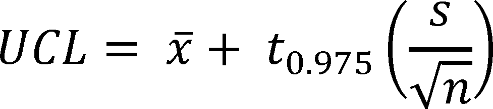
and x̄ is the sample mean; s is the sample standard deviation; n is the number of samples; and t0.975 is the t-statistic for a 97.5-percent one-tailed confidence interval with n-1 degrees of freedom (from appendix A of this subpart).
(iii) For each basic model of battery chargers other than UPSs, using the sample from paragraph (a)(2)(ii) of this section, calculate the represented values of each metric (i.e., maintenance mode power (Pm), standby power (Psb), off mode power (Poff), battery discharge energy (EBatt), 24-hour energy consumption (E24), and duration of the charge and maintenance mode test (tcd)), where the represented value of the metric is:
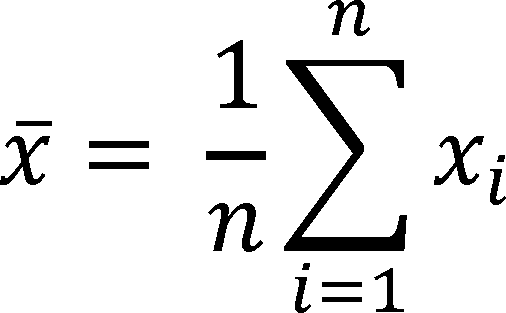
and, x̄ is the sample mean, n is the number of samples, and xi is the measured value of the i th sample for the metric.
(iv) For each basic model of UPSs, the represented value of Effavg must be calculated using one of the following two methods:
(A) A sample of sufficient size must be randomly selected and tested to ensure that the represented value of Effavg is less than or equal to the lower of:
(1) The mean of the sample, where:

and, x̄ is the sample mean; n is the number of samples; and xi is the Effavg of the i th sample; or,
(2) The lower 97.5-percent confidence limit (LCL) of the true mean divided by 0.95, where:

and x̄ is the sample mean; s is the sample standard deviation; n is the number of samples; and t0.975 is the t-statistic for a 97.5-percent one-tailed confidence interval with n-1 degrees of freedom (from appendix A of this subpart).
(B) The represented value of Effavg is equal to the Effavg of the single unit tested.
(b) Certification reports. (1) The requirements of § 429.12 are applicable to all battery chargers.
(2) Pursuant to § 429.12(b)(13), a certification report must include the following product-specific information for all battery chargers other than UPSs: The nameplate battery voltage of the test battery in volts (V), the nameplate battery charge capacity of the test battery in ampere-hours (Ah), and the nameplate battery energy capacity of the test battery in watt-hours (Wh). A certification report must also include the represented values, as determined in paragraph (a) of this section for the maintenance mode power (Pm), standby mode power (Psb), off mode power (Poff), battery discharge energy (Ebatt), 24-hour energy consumption (E24), duration of the charge and maintenance mode test (tcd), and unit energy consumption (UEC).
(3) Pursuant to § 429.12(b)(13), a certification report must include the following product-specific information for all battery chargers other than UPSs: The manufacturer and model of the test battery, and the manufacturer and model, when applicable, of the external power supply.
(4) Pursuant to § 429.12(b)(13), a certification report must include the following product-specific information for all UPSs: Supported input dependency mode(s); active power in watts (W); apparent power in volt-amperes (VA); rated input and output Start Printed Page 89822voltages in volts (V); efficiencies at 25 percent, 50 percent, 75 percent and 100 percent of the reference test load; and average load adjusted efficiency of the lowest and highest input dependency modes.
3. Section 429.110 is amended by revising paragraphs (e)(6), (7), and (8), and adding paragraph (e)(9) to read as follows:
End Amendment PartStart Amendment PartEnforcement testing.* * * * *(e) * * *
(6) For uninterruptible power supplies, if a basic model is certified for compliance to the applicable energy conservation standard(s) in § 430.32 of this chapter according to the sampling plan in § 429.39(a)(2)(iv)(A) of this chapter, DOE will use a sample size of not more than 21 units and follow the sampling plan in appendix A of this subpart (Sampling for Enforcement Testing of Covered Consumer Products and Certain High-Volume Commercial Equipment). If a basic model is certified for compliance to the applicable energy conservation standard(s) in § 430.32 of this chapter according to the sampling plan in § 429.39(a)(2)(iv)(B) of this chapter, DOE will use a sample size of at least one unit and follow the sampling plan in appendix D of this subpart (Sampling for Enforcement Testing of Uninterruptible Power Supplies).
(7) Notwithstanding paragraphs (e)(1) through (6) of this section, if testing of the available or subsequently available units of a basic model would be impractical, as for example when a basic model has unusual testing requirements or has limited production, DOE may in its discretion decide to base the determination of compliance on the testing of fewer than the otherwise required number of units.
(8) When DOE makes a determination in accordance with paragraph (e)(7) of this section to test less than the number of units specified in paragraphs (e)(1) through (6) of this section, DOE will base the compliance determination on the results of such testing in accordance with appendix B of this subpart (Sampling Plan for Enforcement Testing of Covered Equipment and Certain Low-Volume Covered Products) using a sample size (n1) equal to the number of units tested.
(9) For the purposes of this section, available units are those that are available for distribution in commerce within the United States.
4. Section 429.134 is amended by adding paragraph (o) to read as follows:
End Amendment PartStart Amendment PartProduct-specific enforcement provisions.* * * * *(o) Uninterruptible power supplies. (1) Determine the UPS architecture by performing the tests specified in the definitions of VI, VFD, and VFI in sections 2.28.1 through 2.28.3 of appendix Y to subpart B of 10 CFR part 430.
(2) [Reserved]
5. Add appendix D to subpart C of part 429 to read as follows:
End Amendment PartAppendix D to Subpart C of Part 429—Sampling Plan for Enforcement Testing of Uninterruptible Power Supplies
(a) The minimum sample size for enforcement testing will be one unit.
(b) Compute the average load adjusted efficiency (Effavg) of the unit in the sample.
(c) Determine the applicable DOE energy efficiency standard (EES).
(d) If all Effavg are equal to or greater than EES, then the basic model is in compliance and testing is at an end.
(e) If any Effavg is less than EES, then the basic model is in noncompliance and testing is at an end.
Start PartPART 430—ENERGY CONSERVATION PROGRAM FOR CONSUMER PRODUCTS
End Part Start Amendment Part6. The authority citation for part 430 continues to read as follows:
End Amendment Part Start Amendment Part7. Section 430.3 is amended by:
End Amendment Part Start Amendment Parta. Redesignating paragraphs (e)(17) through (20) as (e)(18) through (21) respectively;
End Amendment Part Start Amendment Partb. Adding new paragraph (e)(17);
End Amendment Part Start Amendment Partc. Redesignating paragraphs (p)(3) through (8) as (p)(4) through (9) respectively; and
End Amendment Part Start Amendment Partd. Adding new paragraph (p)(3).
End Amendment PartThe additions read as follows:
Start Amendment PartMaterials incorporated by reference.* * * * *(e) * * *
(17) ANSI/NEMA WD 6-2016, Wiring Devices—Dimensional Specifications, ANSI approved February 11, 2016, IBR approved for Appendix Y to subpart B; as follows:
(i) Figure 1-15—Plug and Receptacle; and
(ii) Figure 5-15—Plug and Receptacle.
* * * * *(p) * * *
(3) IEC Standard 62040-3 Ed. 2.0, (“IEC 62040-3 Ed. 2.0”), Uninterruptible power systems (UPS)—Part 3: Method of specifying the performance and test requirements, Edition 2.0, 2011-03, IBR approved for appendix Y to subpart B, as follows:
(i) Section 5, Electrical conditions, performance and declared values, Section 5.2, UPS input specification, Section 5.2.1—Conditions for normal mode of operation;
(ii) Clause 5.2.2.k;
(iii) Section 5.3, UPS output specification, Section 5.3.2, Characteristics to be declared by the manufacturer, Clause 5.3.2.d;
(iv) Clause 5.3.2.e;
(v) Section 5.3.4—Performance classification;
(vi) Section 6.2, Routine test procedure, Section 6.2.2.7—AC input failure;
(vii) Section 6.4, Type test procedure (electrical), Section 6.4.1—Input—a.c. supply compatibility (excluding 6.4.1.3, 6.4.1.4, 6.4.1.5, 6.4.1.6, 6.4.1.7, 6.4.1.8, 6.4.1.9 and 6.4.1.10);
(viii) Annex G—Input mains failure—Test method
(ix) Annex J—UPS Efficiency—Methods of measurement.
* * * * *8. Section 430.23 is amended by revising paragraph (aa) to read as follows:
End Amendment PartStart Amendment PartTest procedures for the measurement of energy and water consumption.* * * * *(aa) Battery Chargers. (1) Measure the maintenance mode power, standby power, off mode power, battery discharge energy, 24-hour energy consumption and measured duration of the charge and maintenance mode test for a battery charger other than uninterruptible power supplies in accordance with appendix Y to this subpart.
(2) Calculate the unit energy consumption of a battery charger other than uninterruptible power supplies in accordance with appendix Y to this subpart.
(3) Calculate the average load adjusted efficiency of an uninterruptible power supply in accordance with appendix Y to this subpart.
* * * * *9. Appendix Y to subpart B of part 430 is amended by:
End Amendment Part Start Amendment Parta. Revising the introductory text to appendix Y;
End Amendment Part Start Amendment Partb. Revising section 1;
End Amendment Part Start Amendment Partc. Redesignating section 2.24 as 2.28;
End Amendment Part Start Amendment Partd. Adding a new section 2.24;
End Amendment Part Start Amendment Parte. Redesignating sections 2.22 and 2.23 as sections 2.25 and 2.26, respectively;
End Amendment Part Start Amendment Partf. Adding sections 2.27, 2.27.1, 2.27.2, and 2.27.3;
End Amendment Part Start Amendment Partg. Redesignating sections 2.18 through 2.21 as sections 2.20 through 2.23, respectively; Start Printed Page 89823
End Amendment Part Start Amendment Parth. Adding a new section 2.19;
End Amendment Part Start Amendment Parti. Redesignating sections 2.12 through 2.17 as sections 2.13 through 2.18, respectively;
End Amendment Part Start Amendment Partj. Adding a new section 2.12;
End Amendment Part Start Amendment Partk. Revising sections 3 and 4; and
End Amendment Part Start Amendment Partl. Removing section 5.
End Amendment PartThe additions and revisions read as follows:
Start AppendixAppendix Y to Subpart B of Part 430—Uniform Test Method for Measuring the Energy Consumption of Battery Chargers
Prior to November 16, 2016, manufacturers must make any representations regarding the energy consumption of battery chargers other than uninterruptible power supplies based upon results generated under this appendix or the previous version of this appendix as it appeared in the Code of Federal Regulations on January 1, 2016. On or after November 16, 2016, manufacturers must make any representations regarding the energy consumption of battery chargers other than uninterruptible power supplies based upon results generated under this appendix. On or after June 12, 2017, manufacturers must make any representations regarding the energy efficiency of uninterruptible power supplies based upon results generated under this appendix.
1. Scope
This appendix provides the test requirements used to measure the energy consumption of battery chargers operating at either DC or United States AC line voltage (115V at 60Hz). This appendix also provides the test requirements used to measure the energy efficiency of uninterruptible power supplies as defined in section 2 of this appendix that utilize the standardized National Electrical Manufacturer Association (NEMA) plug, 1-15P or 5-15P, as specified in ANSI/NEMA WD 6-2016 (incorporated by reference, see § 430.3) and have an AC output. This appendix does not provide a method for testing back-up battery chargers.
* * * * *2. Definitions
* * * * *2.12. Energy storage system is a system consisting of single or multiple devices designed to provide power to the UPS inverter circuitry.
* * * * *2.19. Normal mode is a mode of operation for a UPS in which:
(1) The AC input supply is within required tolerances and supplies the UPS,
(2) The energy storage system is being maintained at full charge or is under recharge, and
(3) The load connected to the UPS is within the UPS's specified power rating.
* * * * *2.24. Reference test load is a load or a condition with a power factor of greater than 0.99 in which the AC output socket of the UPS delivers the active power (W) for which the UPS is rated.
* * * * *2.27. Uninterruptible power supply or UPS means a battery charger consisting of a combination of convertors, switches and energy storage devices (such as batteries), constituting a power system for maintaining continuity of load power in case of input power failure.
2.27.1. Voltage and frequency dependent UPS or VFD UPS means a UPS that produces an AC output where the output voltage and frequency are dependent on the input voltage and frequency. This UPS architecture does not provide corrective functions like those in voltage independent and voltage and frequency independent systems.
Note to 2.27.1: VFD input dependency may be verified by performing the AC input failure test in section 6.2.2.7 of IEC 62040-3 Ed. 2.0 (incorporated by reference, see § 430.3) and observing that, at a minimum, the UPS switches from normal mode of operation to battery power while the input is interrupted.
2.27.2. Voltage and frequency independent UPS or VFI UPS means a UPS where the device remains in normal mode producing an AC output voltage and frequency that is independent of input voltage and frequency variations and protects the load against adverse effects from such variations without depleting the stored energy source.
Note to 2.27.2: VFI input dependency may be verified by performing the steady state input voltage tolerance test and the input frequency tolerance test in sections 6.4.1.1 and 6.4.1.2 of IEC 62040-3 Ed. 2.0 (incorporated by reference, see § 430.3) respectively and observing that, at a minimum, the UPS produces an output voltage and frequency within the specified output range when the input voltage is varied by ±10% of the rated input voltage and the input frequency is varied by ±2% of the rated input frequency.
2.27.3. Voltage independent UPS or VI UPS means a UPS that produces an AC output within a specific tolerance band that is independent of under-voltage or over-voltage variations in the input voltage without depleting the stored energy source. The output frequency of a VI UPS is dependent on the input frequency, similar to a voltage and frequency dependent system.
Note to 2.27.3: VI input dependency may be verified by performing the steady state input voltage tolerance test in section 6.4.1.1 of IEC 62040-3 Ed. 2.0 (incorporated by reference, see § 430.3) and ensuring that the UPS remains in normal mode with the output voltage within the specified output range when the input voltage is varied by ±10% of the rated input voltage.
* * * * *3. Testing Requirements for all Battery Chargers Other Than Uninterruptible Power Supplies
3.1. Standard Test Conditions
3.1.1 General
The values that may be measured or calculated during the conduct of this test procedure have been summarized for easy reference in Table 3.1.1. of this appendix.
Table 3.1.1—List of Measured or Calculated Values
Name of measured or calculated value Reference 1. Duration of the charge and maintenance mode test Section 3.3.2. 2. Battery Discharge Energy Section 3.3.8. 3. Initial time and power (W) of the input current of connected battery Section 3.3.6. 4. Active and Maintenance Mode Energy Consumption Section 3.3.6. 5. Maintenance Mode Power Section 3.3.9. 6. 24 Hour Energy Consumption Section 3.3.10. 7. Standby Mode Power Section 3.3.11. 8. Off Mode Power Section 3.3.12. 9. Unit Energy Consumption, UEC (kWh/yr) Section 3.3.13. 3.1.2. Verifying Accuracy and Precision of Measuring Equipment
Any power measurement equipment utilized for testing must conform to the uncertainty and resolution requirements outlined in section 4, “General conditions for measurement”, as well as annexes B, “Notes on the measurement of low power modes”, and D, “Determination of uncertainty of measurement”, of IEC 62301 (incorporated by reference, see § 430.3).
3.1.3. Setting Up the Test Room
All tests, battery conditioning, and battery rest periods shall be carried out in a room with an air speed immediately surrounding the UUT of ≤0.5 m/s. The ambient temperature shall be maintained at 20 °C ± 5 °C throughout the test. There shall be no intentional cooling of the UUT such as by use of separately powered fans, air conditioners, or heat sinks. The UUT shall be conditioned, rested, and tested on a thermally non-conductive surface. When not undergoing active testing, batteries shall be stored at 20 °C ± 5 °C.
3.1.4. Verifying the UUT's Input Voltage and Input Frequency
(a) If the UUT is intended for operation on AC line-voltage input in the United States, it shall be tested at 115 V at 60 Hz. If the UUT is intended for operation on AC line-voltage input but cannot be operated at 115 V at 60 Hz, it shall not be tested.
(b) If a charger is powered by a low-voltage DC or AC input, and the manufacturer packages the charger with a wall adapter, sells, or recommends an optional wall adapter capable of providing that low voltage input, then the charger shall be tested using that wall adapter and the input reference source shall be 115 V at 60 Hz. If the wall adapter cannot be operated with AC input voltage at 115 V at 60 Hz, the charger shall not be tested.
(c) If the UUT is designed for operation only on DC input voltage and the provisions of section 3.1.4(b) of this appendix do not apply, it shall be tested with one of the Start Printed Page 89824following input voltages: 5.0 V DC for products drawing power from a computer USB port or the midpoint of the rated input voltage range for all other products. The input voltage shall be within ±1 percent of the above specified voltage.
(d) If the input voltage is AC, the input frequency shall be within ±1 percent of the specified frequency. The THD of the input voltage shall be ≤2 percent, up to and including the 13th harmonic. The crest factor of the input voltage shall be between 1.34 and 1.49.
(e) If the input voltage is DC, the AC ripple voltage (RMS) shall be:
(1) ≤0.2 V for DC voltages up to 10 V; or
(2) ≤2 percent of the DC voltage for DC voltages over 10 V.
3.2. Unit Under Test Setup Requirements
3.2.1. General Setup
(a) The battery charger system shall be prepared and set up in accordance with the manufacturer's instructions, except where those instructions conflict with the requirements of this test procedure. If no instructions are given, then factory or “default” settings shall be used, or where there are no indications of such settings, the UUT shall be tested in the condition as it would be supplied to an end user.
(b) If the battery charger has user controls to select from two or more charge rates (such as regular or fast charge) or different charge currents, the test shall be conducted at the fastest charge rate that is recommended by the manufacturer for everyday use, or, failing any explicit recommendation, the factory-default charge rate. If the charger has user controls for selecting special charge cycles that are recommended only for occasional use to preserve battery health, such as equalization charge, removing memory, or battery conditioning, these modes are not required to be tested. The settings of the controls shall be listed in the report for each test.
3.2.2. Selection and Treatment of the Battery Charger
The UUT, including the battery charger and its associated battery, shall be new products of the type and condition that would be sold to a customer. If the battery is lead-acid chemistry and the battery is to be stored for more than 24 hours between its initial acquisition and testing, the battery shall be charged before such storage.
3.2.3. Selection of Batteries To Use for Testing
(a) For chargers with integral batteries, the battery packaged with the charger shall be used for testing. For chargers with detachable batteries, the battery or batteries to be used for testing will vary depending on whether there are any batteries packaged with the battery charger.
(1) If batteries are packaged with the charger, batteries for testing shall be selected from the batteries packaged with the battery charger, according to the procedure in section 3.2.3(b) of this appendix.
(2) If no batteries are packaged with the charger, but the instructions specify or recommend batteries for use with the charger, batteries for testing shall be selected from those recommended or specified in the instructions, according to the procedure in section 3.2.3(b) of this appendix.
(3) If no batteries are packaged with the charger and the instructions do not specify or recommend batteries for use with the charger, batteries for testing shall be selected from any that are suitable for use with the charger, according to the procedure in section 3.2.3(b) of this appendix.
(b)(1) From the detachable batteries specified above, use Table 3.2.1 of this appendix to select the batteries to be used for testing, depending on the type of battery charger being tested. The battery charger types represented by the rows in the table are mutually exclusive. Find the single applicable row for the UUT, and test according to those requirements. Select only the single battery configuration specified for the battery charger type in Table 3.2.1 of this appendix.
(2) If the battery selection criteria specified in Table 3.2.1 of this appendix results in two or more batteries or configurations of batteries of different chemistries, but with equal voltage and capacity ratings, determine the maintenance mode power, as specified in section 3.3.9 of this appendix, for each of the batteries or configurations of batteries, and select for testing the battery or configuration of batteries with the highest maintenance mode power.
(c) A charger is considered as:
(1) Single-capacity if all associated batteries have the same nameplate battery charge capacity (see definition) and, if it is a batch charger, all configurations of the batteries have the same nameplate battery charge capacity.
(2) Multi-capacity if there are associated batteries or configurations of batteries that have different nameplate battery charge capacities.
(d) The selected battery or batteries will be referred to as the “test battery” and will be used through the remainder of this test procedure.
Table 3.2.1—Battery Selection for Testing
Type of charger Tests to perform Multi-voltage Multi-port Multi-capacity Battery selection (from all configurations of all associated batteries) No No No Any associated battery. No No Yes Highest charge capacity battery. No Yes Yes or No Use all ports. Use the maximum number of identical batteries with the highest nameplate battery charge capacity that the charger can accommodate. Yes No No Highest voltage battery. Yes Yes to either or both Use all ports. Use the battery or configuration of batteries with the highest individual voltage. If multiple batteries meet this criteria, then use the battery or configuration of batteries with the highest total nameplate battery charge capacity at the highest individual voltage. 3.2.4. Limiting Other Non-Battery-Charger Functions
(a) If the battery charger or product containing the battery charger does not have any additional functions unrelated to battery charging, this subsection may be skipped.
(b) Any optional functions controlled by the user and not associated with the battery charging process (e.g., the answering machine in a cordless telephone charging base) shall be switched off. If it is not possible to switch such functions off, they shall be set to their lowest power-consuming mode during the test.
(c) If the battery charger takes any physically separate connectors or cables not required for battery charging but associated with its other functionality (such as phone lines, serial or USB connections, Ethernet, cable TV lines, etc.), these connectors or cables shall be left disconnected during the testing.
(d) Any manual on-off switches specifically associated with the battery charging process shall be switched on for the duration of the charge, maintenance, and no-battery mode tests, and switched off for the off mode test.
3.2.5. Accessing the Battery for the Test
(a) The technician may need to disassemble the end-use product or battery charger to gain access to the battery terminals for the Battery Discharge Energy Test in section 3.3.8 of this appendix. If the battery terminals are not clearly labeled, the technician shall use a voltmeter to identify the positive and negative terminals. These terminals will be the ones that give the largest voltage difference and are able to deliver significant current (0.2 C or 1/hr) into a load.Start Printed Page 89825
(b) All conductors used for contacting the battery must be cleaned and burnished prior to connecting in order to decrease voltage drops and achieve consistent results.
(c) Manufacturer's instructions for disassembly shall be followed, except those instructions that:
(1) Lead to any permanent alteration of the battery charger circuitry or function;
(2) Could alter the energy consumption of the battery charger compared to that experienced by a user during typical use, e.g., due to changes in the airflow through the enclosure of the UUT; or
(3) Conflict requirements of this test procedure.
(d) Care shall be taken by the technician during disassembly to follow appropriate safety precautions. If the functionality of the device or its safety features is compromised, the product shall be discarded after testing.
(e) Some products may include protective circuitry between the battery cells and the remainder of the device. If the manufacturer provides a description for accessing the connections at the output of the protective circuitry, these connections shall be used to discharge the battery and measure the discharge energy. The energy consumed by the protective circuitry during discharge shall not be measured or credited as battery energy.
(f) If the technician, despite diligent effort and use of the manufacturer's instructions, encounters any of the following conditions noted immediately below, the Battery Discharge Energy and the Charging and Maintenance Mode Energy shall be reported as “Not Applicable”:
(1) Inability to access the battery terminals;
(2) Access to the battery terminals destroys charger functionality; or
(3) Inability to draw current from the test battery.
3.2.6. Determining Charge Capacity for Batteries With No Rating
(a) If there is no rating for the battery charge capacity on the battery or in the instructions, then the technician shall determine a discharge current that meets the following requirements. The battery shall be fully charged and then discharged at this constant-current rate until it reaches the end-of-discharge voltage specified in Table 3.3.2 of this appendix. The discharge time must be not less than 4.5 hours nor more than 5 hours. In addition, the discharge test (section 3.3.8 of this appendix) (which may not be starting with a fully-charged battery) shall reach the end-of-discharge voltage within 5 hours. The same discharge current shall be used for both the preparations step (section 3.3.4 of this appendix) and the discharge test (section 3.3.8 of this appendix). The test report shall include the discharge current used and the resulting discharge times for both a fully-charged battery and for the discharge test.
(b) For this section, the battery is considered as “fully charged” when either: it has been charged by the UUT until an indicator on the UUT shows that the charge is complete; or it has been charged by a battery analyzer at a current not greater than the discharge current until the battery analyzer indicates that the battery is fully charged.
(c) When there is no capacity rating, a suitable discharge current must generally be determined by trial and error. Since the conditioning step does not require constant-current discharges, the trials themselves may also be counted as part of battery conditioning.
3.3. Test Measurement
The test sequence to measure the battery charger energy consumption is summarized in Table 3.3.1 of this appendix, and explained in detail in this appendix. Measurements shall be made under test conditions and with the equipment specified in sections 3.1 and 3.2 of this appendix.
Table 3.3.1—Test Sequence
Step/Description Data taken? Equipment needed Test battery Charger Battery analyzer or constant- current load AC power meter Thermometer (for flooded lead-acid battery chargers only) 1. Record general data on UUT; Section 3.3.1 Yes X X 2. Determine test duration; Section 3.3.2 No 3. Battery conditioning; Section 3.3.3 No X X X 4. Prepare battery for charge test; Section 3.3.4 No X X 5. Battery rest period; Section 3.3.5 No X X 6. Conduct Charge Mode and Battery Maintenance Mode Test; Section 3.3.6 Yes X X X 7. Battery Rest Period; Section 3.3.7 No X X 8. Battery Discharge Energy Test; Section 3.3.8 Yes X X 9. Determining the Maintenance Mode Power; Section 3.3.9 Yes X X X 10. Calculating the 24-Hour Energy Consumption; Section 3.3.10 No 11. Standby Mode Test; Section 3.3.11 Yes X X 12. Off Mode Test; Section 3.3.12 Yes X X 3.3.1. Recording General Data on the UUT
The technician shall record:
(a) The manufacturer and model of the battery charger;
(b) The presence and status of any additional functions unrelated to battery charging;
(c) The manufacturer, model, and number of batteries in the test battery;
(d) The nameplate battery voltage of the test battery;
(e) The nameplate battery charge capacity of the test battery; and
(f) The nameplate battery charge energy of the test battery.
(g) The settings of the controls, if battery charger has user controls to select from two or more charge rates.
3.3.2. Determining the Duration of the Charge and Maintenance Mode Test
(a) The charging and maintenance mode test, described in detail in section 3.3.6 of this appendix, shall be 24 hours in length or longer, as determined by the items below. Proceed in order until a test duration is determined.
(1) If the battery charger has an indicator to show that the battery is fully charged, that indicator shall be used as follows: If the indicator shows that the battery is charged after 19 hours of charging, the test shall be terminated at 24 hours. Conversely, if the full-charge indication is not yet present after 19 hours of charging, the test shall continue until 5 hours after the indication is present.
(2) If there is no indicator, but the manufacturer's instructions indicate that charging this battery or this capacity of battery should be complete within 19 hours, the test shall be for 24 hours. If the instructions indicate that charging may take longer than 19 hours, the test shall be run for the longest estimated charge time plus 5 hours.
(3) If there is no indicator and no time estimate in the instructions, but the charging current is stated on the charger or in the Start Printed Page 89826instructions, calculate the test duration as the longer of 24 hours or:

(b) If none of the above applies, the duration of the test shall be 24 hours.
3.3.3. Battery Conditioning
(a) No conditioning is to be done on lithium-ion batteries. The test technician shall proceed directly to battery preparation, section 3.3.4 of this appendix, when testing chargers for these batteries.
(b) Products with integral batteries will have to be disassembled per the instructions in section 3.2.5 of this appendix, and the battery disconnected from the charger for discharging.
(c) Batteries of other chemistries that have not been previously cycled are to be conditioned by performing two charges and two discharges, followed by a charge, as below. No data need be recorded during battery conditioning.
(1) The test battery shall be fully charged for the duration specified in section 3.3.2 of this appendix or longer using the UUT.
(2) The test battery shall then be fully discharged using either:
(i) A battery analyzer at a rate not to exceed 1 C, until its average cell voltage under load reaches the end-of-discharge voltage specified in Table 3.3.2 of this appendix for the relevant battery chemistry; or
(ii) The UUT, until the UUT ceases operation due to low battery voltage.
(3) The test battery shall again be fully charged as in step (c)(1) of this section.
(4) The test battery shall again be fully discharged as per step (c)(2) of this section.
(5) The test battery shall be again fully charged as in step (c)(1) of this section.
(d) Batteries of chemistries, other than lithium-ion, that are known to have been through at least two previous full charge/discharge cycles shall only be charged once per step (c)(5), of this section.
3.3.4. Preparing the Battery for Charge Testing
Following any conditioning prior to beginning the battery charge test (section 3.3.6 of this appendix), the test battery shall be fully discharged for the duration specified in section 3.3.2 of this appendix, or longer using a battery analyzer.
3.3.5. Resting the Battery
The test battery shall be rested between preparation and the battery charge test. The rest period shall be at least one hour and not exceed 24 hours. For batteries with flooded cells, the electrolyte temperature shall be less than 30 °C before charging, even if the rest period must be extended longer than 24 hours.
3.3.6. Testing Charge Mode and Battery Maintenance Mode
(a) The Charge and Battery Maintenance Mode test measures the energy consumed during charge mode and some time spent in the maintenance mode of the UUT. Functions required for battery conditioning that happen only with some user-selected switch or other control shall not be included in this measurement. (The technician shall manually turn off any battery conditioning cycle or setting.) Regularly occurring battery conditioning or maintenance functions that are not controlled by the user will, by default, be incorporated into this measurement.
(b) During the measurement period, input power values to the UUT shall be recorded at least once every minute.
(1) If possible, the technician shall set the data logging system to record the average power during the sample interval. The total energy is computed as the sum of power samples (in watts) multiplied by the sample interval (in hours).
(2) If this setting is not possible, then the power analyzer shall be set to integrate or accumulate the input power over the measurement period and this result shall be used as the total energy.
(c) The technician shall follow these steps:
(1) Ensure that the user-controllable device functionality not associated with battery charging and any battery conditioning cycle or setting are turned off, as instructed in section 3.2.4 of this appendix;
(2) Ensure that the test battery used in this test has been conditioned, prepared, discharged, and rested as described in sections 3.3.3 through 3.3.5 of this appendix;
(3) Connect the data logging equipment to the battery charger;
(4) Record the start time of the measurement period, and begin logging the input power;
(5) Connect the test battery to the battery charger within 3 minutes of beginning logging. For integral battery products, connect the product to a cradle or wall adapter within 3 minutes of beginning logging;
(6) After the test battery is connected, record the initial time and power (W) of the input current to the UUT. These measurements shall be taken within the first 10 minutes of active charging;
(7) Record the input power for the duration of the “Charging and Maintenance Mode Test” period, as determined by section 3.3.2 of this appendix. The actual time that power is connected to the UUT shall be within ±5 minutes of the specified period; and
(8) Disconnect power to the UUT, terminate data logging, and record the final time.
3.3.7. Resting the Battery
The test battery shall be rested between charging and discharging. The rest period shall be at least 1 hour and not more than 4 hours, with an exception for flooded cells. For batteries with flooded cells, the electrolyte temperature shall be less than 30 °C before charging, even if the rest period must be extended beyond 4 hours.
3.3.8. Battery Discharge Energy Test
(a) If multiple batteries were charged simultaneously, the discharge energy is the sum of the discharge energies of all the batteries.
(1) For a multi-port charger, batteries that were charged in separate ports shall be discharged independently.
(2) For a batch charger, batteries that were charged as a group may be discharged individually, as a group, or in sub-groups connected in series and/or parallel. The position of each battery with respect to the other batteries need not be maintained.
(b) During discharge, the battery voltage and discharge current shall be sampled and recorded at least once per minute. The values recorded may be average or instantaneous values.
(c) For this test, the technician shall follow these steps:
(1) Ensure that the test battery has been charged by the UUT and rested according to the procedures above.
(2) Set the battery analyzer for a constant discharge rate and the end-of-discharge voltage in Table 3.3.2 of this appendix for the relevant battery chemistry.
(3) Connect the test battery to the analyzer and begin recording the voltage, current, and wattage, if available from the battery analyzer. When the end-of-discharge voltage is reached or the UUT circuitry terminates the discharge, the test battery shall be returned to an open-circuit condition. If current continues to be drawn from the test battery after the end-of-discharge condition is first reached, this additional energy is not to be counted in the battery discharge energy.
(d) If not available from the battery analyzer, the battery discharge energy (in watt-hours) is calculated by multiplying the voltage (in volts), current (in amperes), and sample period (in hours) for each sample, and then summing over all sample periods until the end-of-discharge voltage is reached.
3.3.9. Determining the Maintenance Mode Power
After the measurement period is complete, the technician shall determine the average maintenance mode power consumption by examining the power-versus-time data from the charge and maintenance test and:
(a) If the maintenance mode power is cyclic or shows periodic pulses, compute the average power over a time period that spans a whole number of cycles and includes at least the last 4 hours.
(b) Otherwise, calculate the average power value over the last 4 hours.
3.3.10. Determining the 24-Hour Energy Consumption
The accumulated energy or the average input power, integrated over the test period Start Printed Page 89827from the charge and maintenance mode test, shall be used to calculate 24-hour energy consumption.
Table 3.3.2—Required Battery Discharge Rates and End-of-Discharge Battery Voltages
Battery chemistry Discharge rate (C) End-of-discharge voltage * (volts per cell) Valve-Regulated Lead Acid (VRLA) 0.2 1.75 Flooded Lead Acid 0.2 1.70 Nickel Cadmium (NiCd) 0.2 1.0 Nickel Metal Hydride (NiMH) 0.2 1.0 Lithium Ion (Li-Ion) 0.2 2.5 Lithium Polymer 0.2 2.5 Rechargeable Alkaline 0.2 0.9 Nanophosphate Lithium Ion 0.2 2.0 Silver Zinc 0.2 1.2 * If the presence of protective circuitry prevents the battery cells from being discharged to the end-of-discharge voltage specified, then discharge battery cells to the lowest possible voltage permitted by the protective circuitry. 3.3.11. Standby Mode Energy Consumption Measurement
The standby mode measurement depends on the configuration of the battery charger, as follows.
(a) Conduct a measurement of standby power consumption while the battery charger is connected to the power source. Disconnect the battery from the charger, allow the charger to operate for at least 30 minutes, and record the power (i.e., watts) consumed as the time series integral of the power consumed over a 10-minute test period, divided by the period of measurement. If the battery charger has manual on-off switches, all must be turned on for the duration of the standby mode test.
(b) Standby mode may also apply to products with integral batteries. If the product uses a cradle and/or adapter for power conversion and charging, then “disconnecting the battery from the charger” will require disconnection of the end-use product, which contains the batteries. The other enclosures of the battery charging system will remain connected to the main electricity supply, and standby mode power consumption will equal that of the cradle and/or adapter alone.
(c) If the product is powered through a detachable AC power cord and contains integrated power conversion and charging circuitry, then only the cord will remain connected to mains, and standby mode power consumption will equal that of the AC power cord (i.e., zero watts).
(d) Finally, if the product contains integrated power conversion and charging circuitry but is powered through a non-detachable AC power cord or plug blades, then no part of the system will remain connected to mains, and standby mode measurement is not applicable.
3.3.12. Off Mode Energy Consumption Measurement
The off mode measurement depends on the configuration of the battery charger, as follows.
(a) If the battery charger has manual on-off switches, record a measurement of off mode energy consumption while the battery charger is connected to the power source. Remove the battery from the charger, allow the charger to operate for at least 30 minutes, and record the power (i.e., watts) consumed as the time series integral of the power consumed over a 10-minute test period, divided by the period of measurement, with all manual on-off switches turned off. If the battery charger does not have manual on-off switches, record that the off mode measurement is not applicable to this product.
(b) Off mode may also apply to products with integral batteries. If the product uses a cradle and/or adapter for power conversion and charging, then “disconnecting the battery from the charger” will require disconnection of the end-use product, which contains the batteries. The other enclosures of the battery charging system will remain connected to the main electricity supply, and off mode power consumption will equal that of the cradle and/or adapter alone.
(c) If the product is powered through a detachable AC power cord and contains integrated power conversion and charging circuitry, then only the cord will remain connected to mains, and off mode power consumption will equal that of the AC power cord (i.e., zero watts).
(d) Finally, if the product contains integrated power conversion and charging circuitry but is powered through a non-detachable AC power cord or plug blades, then no part of the system will remain connected to mains, and off mode measurement is not applicable.
3.3.13. Unit Energy Consumption Calculation
Unit energy consumption (UEC) shall be calculated for a battery charger using one of the two equations (equation (i) or equation (ii)) listed in this section. If a battery charger is tested and its charge duration as determined in section 3.3.2 of this appendix minus 5 hours is greater than the threshold charge time listed in table 3.3.3 of this appendix (i.e. (tcd − 5) * n > ta&m), equation (ii) shall be used to calculate UEC; otherwise a battery charger's UEC shall be calculated using equation (i).
End Appendix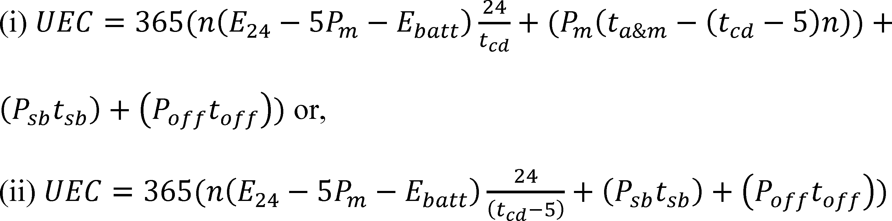
Where:
E24 = 24-hour energy as determined in section 3.3.10 of this appendix,
Ebatt = Measured battery energy as determined in section 3.3.8 of this appendix,
Pm = Maintenance mode power as determined in section 3.3.9 of this appendix,
Psb = Standby mode power as determined in section 3.3.11 of this appendix,Start Printed Page 89828
Poff = Off mode power as determined in section 3.3.12 of this appendix,
tcd = Charge test duration as determined in section 3.3.2 of this appendix, and
ta&m, n, tsb, and toff, are constants used depending upon a device's product class and found in the following table:
Table 3.3.3—Battery Charger Usage Profiles
Product class Hours per day *** Charges (n) Threshold charge time * Number Description Rated battery energy (ebatt) ** Special characteristic or battery voltage Active + maintenance (ta&m) Standby (tsb) Off (toff) Number per day Hours 1 Low-Energy ≤5 Wh Inductive Connection **** 20.66 0.10 0.00 0.15 137.73 2 Low-Energy, Low-Voltage <100 Wh <4 V 7.82 5.29 0.00 0.54 14.48 3 Low-Energy, Medium-Voltage 4-10 V 6.42 0.30 0.00 0.10 64.20 4 Low-Energy, High-Voltage >10 V 16.84 0.91 0.00 0.50 33.68 5 Medium-Energy, Low-Voltage 100-3000 Wh <20 V 6.52 1.16 0.00 0.11 59.27 6 Medium-Energy, High-Voltage ≥20 V 17.15 6.85 0.00 0.34 50.44 7 High-Energy >3000 Wh 8.14 7.30 0.00 0.32 25.44 * If the duration of the charge test (minus 5 hours) as determined in section 3.3.2 of appendix Y to subpart B of this part exceeds the threshold charge time, use equation (ii) to calculate UEC otherwise use equation (i). ** Ebatt = Rated battery energy as determined in 10 CFR part 429.39(a). *** If the total time does not sum to 24 hours per day, the remaining time is allocated to unplugged time, which means there is 0 power consumption and no changes to the UEC calculation needed. **** Inductive connection and designed for use in a wet environment (e.g. electric toothbrushes). 4. Testing Requirements for Uninterruptible Power Supplies
4.1. Standard Test Conditions
4.1.1. Measuring Equipment
(a) The power or energy meter must provide true root mean square (r. m. s) measurements of the active input and output measurements, with an uncertainty at full rated load of less than or equal to 0.5% at the 95% confidence level notwithstanding that voltage and current waveforms can include harmonic components. The meter must measure input and output values simultaneously.
(b) All measurement equipment used to conduct the tests must be calibrated within the measurement equipment manufacturer specified calibration period by a standard traceable to International System of Units such that measurements meet the uncertainty requirements specified in section 4.1.1(a) of this appendix.
4.1.2. Test Room Requirements
All portions of the test must be carried out in a room with an air speed immediately surrounding the UUT of ≤0.5 m/s in all directions. Maintain the ambient temperature in the range of 20.0 °C to 30.0 °C, including all inaccuracies and uncertainties introduced by the temperature measurement equipment, throughout the test. No intentional cooling of the UUT, such as by use of separately powered fans, air conditioners, or heat sinks, is permitted. Test the UUT on a thermally non-conductive surface.
4.1.3. Input Voltage and Input Frequency
The AC input voltage and frequency to the UPS during testing must be within 3 percent of the highest rated voltage and within 1 percent of the highest rated frequency of the device.
4.2. Unit Under Test Setup Requirements
4.2.1. General Setup
Configure the UPS according to Annex J.2 of IEC 62040-3 Ed. 2.0 (incorporated by reference, see § 430.3) with the following additional requirements:
(a) UPS Operating Mode Conditions. If the UPS can operate in two or more distinct normal modes as more than one UPS architecture, conduct the test in its lowest input dependency as well as in its highest input dependency mode where VFD represents the lowest possible input dependency, followed by VI and then VFI.
(b) Energy Storage System. The UPS must not be modified or adjusted to disable energy storage charging features. Minimize the transfer of energy to and from the energy storage system by ensuring the energy storage system is fully charged (at the start of testing) as follows:
(1) If the UUT has a battery charge indicator, charge the battery for 5 hours after the UUT has indicated that it is fully charged.
(2) If the UUT does not have a battery charge indicator but the user manual shipped with the UUT specifies a time to reach full charge, charge the battery for 5 hours longer than the time specified.
(3) If the UUT does not have a battery charge indicator or user manual instructions, charge the battery for 24 hours.
(c) DC output port(s). All DC output port(s) of the UUT must remain unloaded during testing.
4.2.2. Additional Features
(a) Any feature unrelated to maintaining the energy storage system at full charge or delivery of load power (e.g., LCD display) shall be switched off. If it is not possible to switch such features off, they shall be set to their lowest power-consuming mode during the test.
(b) If the UPS takes any physically separate connectors or cables not required for maintaining the energy storage system at full charge or delivery of load power but associated with other features (such as serial or USB connections, Ethernet, etc.), these connectors or cables shall be left disconnected during the test.
(c) Any manual on-off switches specifically associated with maintaining the energy storage system at full charge or delivery of load power shall be switched on for the duration of the test.Start Printed Page 89829
4.3. Test Measurement and Calculation
Efficiency can be calculated from either average power or accumulated energy.
4.3.1. Average Power Calculations
If efficiency calculation are to be made using average power, calculate the average power consumption (Pavg) by sampling the power at a rate of at least 1 sample per second and computing the arithmetic mean of all samples over the time period specified for each test as follows:

Where:
Pavg = average power
Pi = power measured during individual measurement (i)
n = total number of measurements
4.3.2. Steady State
Operate the UUT and the load for a sufficient length of time to reach steady state conditions. To determine if steady state conditions have been attained, perform the following steady state check, in which the difference between the two efficiency calculations must be less than 1 percent:
(a)(1) Simultaneously measure the UUT's input and output power for at least 5 minutes, as specified in section 4.3.1 of this appendix, and record the average of each over the duration as Pavg_in and Pavg_out, respectively. Or,
(2) Simultaneously measure the UUT's input and output energy for at least 5 minutes and record the accumulation of each over the duration as Ein and Eout, respectively.
(b) Calculate the UUT's efficiency, Eff1, using one of the following two equations:
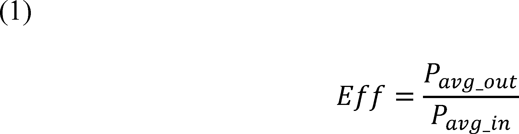
Where:
Eff is the UUT efficiency
Pavg_out is the average output power in watts
Pavg_in is the average input power in watts

Where:
Eff is the UUT efficiency
Eout is the accumulated output energy in watt-hours
Ein in the accumulated input energy in watt-hours
(c) Wait a minimum of 10 minutes.
(d) Repeat the steps listed in paragraphs (a) and (b) of section 4.3.2 of this appendix to calculate another efficiency value, Eff2.
(e) Determine if the product is at steady state using the following equation:

If the percentage difference of Eff1 and Eff2 as described in the equation, is less than 1 percent, the product is at steady state.
(f) If the percentage difference is greater than or equal to 1 percent, the product is not at steady state. Repeat the steps listed in paragraphs (c) to (e) of section 4.3.2 of this appendix until the product is at steady state.
4.3.3. Power Measurements and Efficiency Calculations
Measure input and output power of the UUT according to Section J.3 of Annex J of IEC 62040-3 Ed. 2.0 (incorporated by reference, see § 430.3), or measure the input and output energy of the UUT for efficiency calculations with the following exceptions:
(a) Test the UUT at the following reference test load conditions, in the following order: 100 percent, 75 percent, 50 percent, and 25 percent of the rated output power.
(b) Perform the test at each of the reference test loads by simultaneously measuring the UUT's input and output power in Watts (W), or input and output energy in Watt-Hours (Wh) over a 15 minute test period at a rate of at least 1 Hz. Calculate the efficiency for that reference load using one of the following two equations:
Start Printed Page 89830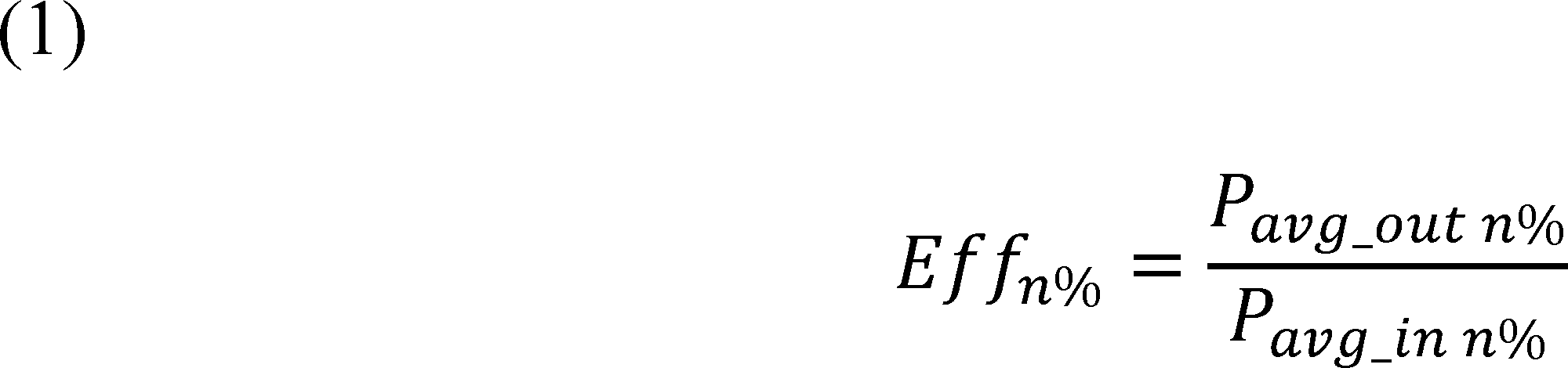
Where:
Effn% = the efficiency at reference test load n%
Pavg_out n% = the average output power at reference load n%
Pavg_in n% = the average input power at reference load n%
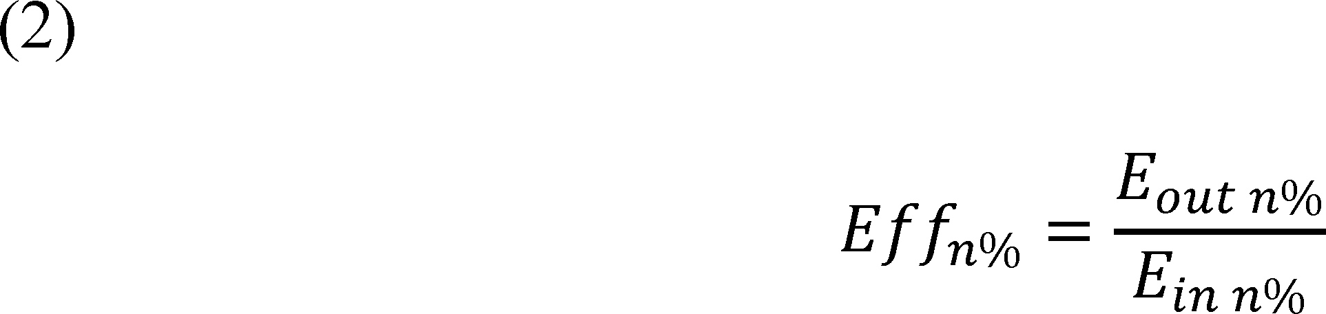
Where:
Effn% = the efficiency at reference test load n%
Eout n% = the accumulated output energy at reference load n%
Ein n% = the accumulated input energy at reference load n%
4.3.4. UUT Classification
Optional Test for determination of UPS architecture. Determine the UPS architecture by performing the tests specified in the definitions of VI, VFD, and VFI (sections 2.28.1 through 2.28.3 of this appendix).
4.3.5. Output Efficiency Calculation
(a) Use the load weightings from Table 4.3.1 to determine the average load adjusted efficiency as follows:

Where:
Effavg = the average load adjusted efficiency
tn% = the portion of time spent at reference test load n% as specified in Table 4.3.1
Eff|n% = the measured efficiency at reference test load n%
Table 4.3.1—Load Weightings
Rated output power (W) UPS architecture Portion of time spent at reference load 25% 50% 75% 100% P ≤ 1500 W VFD 0.2 0.2 0.3 0.3 VI or VFI 0 * 0.3 0.4 0.3 P > 1500 W VFD, VI, or VFI 0 * 0.3 0.4 0.3 * Measuring efficiency at loading points with 0 time weighting is not required. (b) Round the calculated efficiency value to one tenth of a percentage point.
End Supplemental InformationFootnotes
1. All references to EPCA refer to the statute as amended through the Energy Efficiency Improvement Act, Public Law 114-11 (April 30, 2015).
Back to Citation2. For editorial reasons, Part B was redesignated as Part A upon incorporation into the U.S. Code (42 U.S.C. 6291-6309, as codified).
Back to Citation3. In the May 2016 NOPR, DOE used the terms `average normal mode loading efficiency' and `average load adjusted efficiency' interchangeably. For consistency, DOE is updating this final rule to only use the term average load adjusted efficiency.'
Back to Citation4. ENERGY STAR, Energy Star Certified Products. Available at http://www.energystar.gov/. Last accessed November 14, 2016.
Back to Citation[FR Doc. 2016-28972 Filed 12-9-16; 8:45 am]
BILLING CODE 6450-01-P


Document Information
- Effective Date:
- 1/11/2017
- Published:
- 12/12/2016
- Department:
- Energy Department
- Entry Type:
- Rule
- Action:
- Final rule.
- Document Number:
- 2016-28972
- Dates:
- The effective date of this rule is January 11, 2017. The final rule changes will be mandatory for representations starting June 12, 2017. The incorporation by reference of certain publications listed in this rule is approved by the Director of the Federal Register on January 11, 2017.
- Pages:
- 89806-89830 (25 pages)
- Docket Numbers:
- Docket No. EERE-2016-BT-TP-0018
- RINs:
- 1904-AD68: Test Procedure for Battery Chargers That are Uninterruptible Power Supplies
- RIN Links:
- https://www.federalregister.gov/regulations/1904-AD68/test-procedure-for-battery-chargers-that-are-uninterruptible-power-supplies
- Topics:
- Administrative practice and procedure, Confidential business information, Energy conservation, Household appliances, Imports, Incorporation by reference, Intergovernmental relations, Reporting and recordkeeping requirements, Small businesses
- PDF File:
- 2016-28972.pdf
- Supporting Documents:
- » 2022-05-11 Energy Conservation Program: Test Procedure for Uninterruptible Power Supplies; Correction; Correcting amendment
- » 2016-12-12 Energy Conservation Program: Test Procedure for Uninterruptible Power Supplies; Final rule.
- » 2016-06-09 Public Meeting Transcript: Battery Chargers (Uninterruptible Power Supplies) Test Procedure Meeting
- » 2016-06-09 Public Meeting Presentation: Uninterruptible Power Supply Test Procedure Notice of Proposed Rulemaking Public Meeting
- » 2016-05-19 Energy Conservation Program: Test Procedures for Uninterruptible Power Supplies; Notice of Proposed rulemaking
- CFR: (5)
- 10 CFR 429.39
- 10 CFR 429.110
- 10 CFR 429.134
- 10 CFR 430.3
- 10 CFR 430.23