2012-22348. Greenhouse Gas Reporting Program: Proposed Amendments and Confidentiality Determinations for Subpart I
-
Start Preamble
Start Printed Page 63538
AGENCY:
Environmental Protection Agency (EPA).
ACTION:
Proposed rule; Grant of Reconsideration.
SUMMARY:
This action proposes amending the calculation and monitoring methodologies for the Electronics Manufacturing, of the Greenhouse Gas Reporting Rule. Proposed changes include revising certain calculation methods and adding a new method, amending data reporting requirements, and clarifying terms and definitions. This action also proposes confidentiality determinations for the reporting of the new and revised data elements. Many of these proposed actions are in response to a petition to reconsider specific aspects of our regulations. This document also proposes amendments to the General Provisions of the Greenhouse Gas Reporting Rule to reflect proposed changes to the reporting requirements for the Electronics Manufacturing sector.
DATES:
Comments. Comments must be received on or before December 17, 2012.
Public Hearing. The EPA does not plan to conduct a public hearing unless requested. To request a hearing, please contact the person listed in the FOR FURTHER INFORMATION CONTACT section by October 23, 2012. Upon such request, the EPA will hold the hearing on October 31, 2012 in the Washington, DC area starting at 9 a.m., local time. The EPA will provide further information about the hearing on its Web page if a hearing is requested.
ADDRESSES:
Submit your comments, identified by Docket ID No. EPA-HQ-OAR-2011-0028, by one of the following methods:
- Federal eRulemaking Portal: http://www.regulations.gov. Follow the online instructions for submitting comments.
- Email: GHGReportingCBI@epa.gov.
- Fax: (202) 566-1741.
- Mail: Environmental Protection Agency, EPA Docket Center (EPA/DC), Mailcode 6102T, Attention Docket ID No. EPA-HQ-OAR-2011-0028, 1200 Pennsylvania Avenue NW., Washington, DC 20460.
- Hand Delivery: EPA Docket Center, Public Reading Room, EPA West Building, Room 3334, 1301 Constitution Avenue NW., Washington, DC 20004. Such deliveries are only accepted during the Docket's normal hours of operation, and special arrangements should be made for deliveries of boxed information.
Instructions: Direct your comments to Docket ID No. EPA-HQ-OAR-2011-0028. The EPA's policy is that all comments received will be included in the public docket without change and may be made available online at http://www.regulations.gov, including any personal information provided, unless the comment includes information claimed to be confidential business information (CBI) or other information whose disclosure is restricted by statute.
Do not submit information that you consider to be CBI or otherwise protected through http://www.regulations.gov or email. Send or deliver information identified as CBI to only the mail or hand/courier delivery address listed above, attention: Docket ID No. EPA-HQ-OAR-2011-0028. The http://www.regulations.gov Web site is an “anonymous access” system, which means the EPA will not know your identity or contact information unless you provide it in the body of your comment. If you send an email comment directly to the EPA without going through http://www.regulations.gov,, your email address will be automatically captured and included as part of the comment that is placed in the public docket and made available on the Internet. If you submit an electronic comment, the EPA recommends that you include your name and other contact information in the body of your comment and with any disk or CD-ROM you submit. If the EPA cannot read your comment due to technical difficulties and cannot contact you for clarification, the EPA may not be able to consider your comment. Electronic files should avoid the use of special characters, any form of encryption, and be free of any defects or viruses.
Docket: All documents in the docket are listed in the http://www.regulations.gov index. Although listed in the index, some information is not publicly available, e.g., CBI or other information whose disclosure is restricted by statute. Certain other material, such as copyrighted material, will be publicly available only in hard copy. Publicly available docket materials are available either electronically in http://www.regulations.gov or in hard copy at the Air Docket, EPA/DC, EPA West, Room B102, 1301 Constitution Ave. NW., Washington, DC. This Docket Facility is open from 8:30 a.m. to 4:30 p.m., Monday through Friday, excluding legal holidays. The telephone number for the Public Reading Room is (202) 566-1744, and the telephone number for the Air Docket is (202) 566-1742.
Start Further InfoFOR FURTHER GENERAL INFORMATION CONTACT:
Carole Cook, Climate Change Division, Office of Atmospheric Programs (MC-6207J), Environmental Protection Agency, 1200 Pennsylvania Ave. NW., Washington, DC 20460; telephone number: (202) 343-9263; fax number: (202) 343-2342; email address: GHGReportingRule@epa.gov. For technical information, contact the Greenhouse Gas Reporting Rule Hotline at: http://www.epa.gov/climatechange/emissions/ghgrule_contactus.htm Alternatively, contact Carole Cook at (202) 343-9263.
End Further Info End Preamble Start Supplemental InformationSUPPLEMENTARY INFORMATION:
Additional information on submitting comments: To expedite review of your comments by agency staff, you are encouraged to send a separate copy of your comments, in addition to the copy you submit to the official docket, to Carole Cook, U.S. EPA, Office of Atmospheric Programs, Climate Change Division, Mail Code 6207-J, Washington, DC 20460, telephone (202) 343-9263, email address: GHGReportingRule@epa.gov.
Worldwide Web (WWW). In addition to being available in the docket, an electronic copy of this proposal, memoranda to the docket, and all other related information will also be available through the WWW on the EPA's Greenhouse Gas Reporting Rule Web site at http://www.epa.gov/climatechange/.
Acronyms and Abbreviations. The following acronyms and abbreviations are used in this document.
BAMM best available monitoring methods
CAA Clean Air Act
CO2 e carbon dioxide equivalent
CBI confidential business information
CFR Code of Federal Regulations
CVD chemical vapor deposition
DRE destruction or removal efficiency
EIA Economic Impact Analysis
EPA U.S. Environmental Protection Agency
F-GHG fluorinated greenhouse gas
FDL field detection limit
FTIR Fourier transform infrared
GHG greenhouse gas
GWP global warming potential
HTF heat transfer fluid
ICR Information Collection Request
IPCC Intergovernmental Panel on Climate Change
ISBN International Standard Book Number
ISMI International SEMATECH Manufacturing InitiativeStart Printed Page 63539
LCD liquid crystal display
MEMS micro-electro-mechanical systems
mtCO2 e metric ton carbon dioxide equivalent
NAICS North American Industrial Classification System
N2 O nitrous oxide
NTTAA National Technology Transfer and Advancement Act of 1995
OMB Office of Management & Budget
PFC perfluorocarbon
POU point of use
ppbv parts per billion by volume
QMS quadrupole mass spectroscopy
RFA Regulatory Flexibility Act
RSASTP random sampling abatement system testing program
RSD relative standard deviation
SEMATECH SEmiconductor MAnufacturing TECHnology
SIA Semiconductor Industry Association
UMRA Unfunded Mandates Reform Act of 1995
U.S. United States
VCS voluntary consensus standard
WWW Worldwide Web
Organization of This Document. The following outline is provided to aid in locating information in this preamble.
I. General Information
A. What is the purpose of this action?
B. Does this action apply to me?
C. Legal Authority
D. What should I consider as I prepare my comments to the EPA?
II. Background for Proposed Amendments to GHG Monitoring and Calculation Methodologies and Other Technical Revisions
A. Background for Proposed Amendments
B. How would these amendments apply to 2012 and 2013 reports?
III. Summary and Rationale for Proposed Amendments to GHG Monitoring and Calculation Methodologies and Other Revisions
A. Summary of Proposed Rule Amendments in Response to Petition for Reconsideration
B. Rationale for Proposed Amendments
C. Proposed Rule Changes to Reporting and Recordkeeping Requirements
D. Proposed Changes to Remove BAMM Provisions and Language Specific to Reporting Years 2011, 2012, and 2013.
IV. Background for Confidentiality Determinations for Subpart I of Part 98
A. Overview and Background
B. Approach to Proposed CBI Determinations for New or Revised Subpart I Data Elements
C. Proposed Confidentiality Determinations for Individual Data Elements in Two Direct Emitter Data Categories
D. Request for Comments on Proposed Confidentiality Determinations
V. Statutory and Executive Order Reviews
A. Executive Order 12866: Regulatory Planning and Review and Executive Order 13563: Improving Regulation and Regulatory Review
B. Paperwork Reduction Act
C. Regulatory Flexibility Act (RFA)
D. Unfunded Mandates Reform Act (UMRA)
E. Executive Order 13132: Federalism
F. Executive Order 13175: Consultation and Coordination with Indian Tribal Governments
G. Executive Order 13045: Protection of Children from Environmental Health Risks and Safety Risks
H. Executive Order 13211: Actions that Significantly Affect Energy Supply, Distribution, or Use
I. National Technology Transfer and Advancement Act
J. Executive Order 12898: Federal Actions to Address Environmental Justice in Minority Populations and Low-Income Populations
I. General Information
A. What is the purpose of this action?
The EPA is proposing amendments to the calculation and monitoring methodologies for Subpart I, Electronics Manufacturing, of the Greenhouse Gas Reporting Rule (“subpart I”). In addition, the EPA is proposing conforming changes to the reporting and recordkeeping requirements of subpart I. Changes include revising certain calculation methods and adding a new method, amending data reporting requirements, and clarifying terms and definitions. The EPA is proposing these amendments to (1) Modify calculation methods and data requirements to better reflect new industry data and current practice; (2) provide additional calculation methods to allow individual facilities to choose the method best suited for their operations; (3) reduce the burden associated with existing requirements; and (4) address sensitive business information concerns raised by members of the Semiconductor Industry Association (SIA). Amendments being proposed today affect all facilities that manufacture electronics including those that manufacture semiconductors (including light emitting diodes), micro-electro-mechanical systems (MEMS), liquid crystal displays (LCDs), or photovoltaic (PV) cells. Because we are planning an effective date of January 1, 2014 for the final amendments, we are also proposing to remove the rule language for certain provisions that will not apply after 2013. Sections II and III of this preamble contain more detailed information on the background and rationale for these proposed amendments. Many of the proposed changes are in response to a petition to reconsider specific aspects of subpart I.
The EPA is also proposing confidentiality determinations for the new and revised data elements under the proposed amendments to subpart I. Section IV of this preamble provides the background and rationale for these proposed confidentiality determinations. Finally, Section V of this preamble describes the statutory and executive order requirements applicable to this action.
B. Does this action apply to me?
This proposal affects entities that are required to submit annual greenhouse gas (GHG) reports under subpart I of 40 CFR part 98 (“Part 98”). The Administrator determined that this action is subject to the provisions of Clean Air Act (CAA) section 307(d). See CAA section 307(d)(1)(V) (the provisions of CAA section 307(d) apply to “such other actions as the Administrator may determine”). Part 98 and this action affect owners and operators of electronics manufacturing facilities. Affected categories and entities include those listed in Table 1 of this preamble.
Table 1—Examples of Affected Entities by Category
Category NAICS Examples of affected facilities Electronics Manufacturing 334111 Microcomputers manufacturing facilities. 334413 Semiconductor, photovoltaic (solid-state) device manufacturing facilities. 334419 Liquid crystal display unit screens manufacturing facilities. 334419 Micro-electro-mechanical systems manufacturing facilities. Table 1 of this preamble lists the types of entities that potentially could be affected by the reporting requirements under the subpart covered by this proposal. However, this list is not intended to be exhaustive, but rather provides a guide for readers regarding facilities likely to be affected by this action. Other types of facilities not listed in the table could also be subject to reporting requirements. To determine whether you are affected by this action, Start Printed Page 63540you should carefully examine the applicability criteria found in 40 CFR part 98, subpart A as well as 40 CFR part 98, subpart I. If you have questions regarding the applicability of this action to a particular facility, consult the person listed in the FOR FURTHER INFORMATION CONTACT section of this preamble.
C. Legal Authority
The EPA is proposing rule amendments to Part 98 under its existing CAA authority, specifically authorities provided in CAA section 114. As stated in the preamble to the 2009 final rule (74 FR 56260, October 30, 2009) and the Response to Comments on the Proposed Rule, Volume 9, Legal Issues, CAA section 114 provides the EPA broad authority to obtain the information in Part 98, including subpart I, because such data would inform and are relevant to the EPA's carrying out a wide variety of CAA provisions. As discussed in the preamble to the initial Part 98 proposal (74 FR 16448, April 10, 2009), CAA section 114(a)(1) authorizes the Administrator to require emissions sources, persons subject to the CAA, manufacturers of control or process equipment, or persons whom the Administrator believes may have necessary information to monitor and report emissions and provide such other information the Administrator requests for the purposes of carrying out any provision of the CAA.
In addition, the EPA is proposing confidentiality determinations for proposed data elements in subpart I, under its authorities provided in sections 114, 301, and 307 of the CAA. As mentioned, CAA section 114 provides the EPA authority to obtain the information in Part 98, including those in subpart I. Section 114(c) requires that the EPA make publicly available information obtained under section 114 except for information (excluding emission data) that qualify for confidential treatment.
The Administrator has determined that this action (proposed amendments and confidentiality determinations) is subject to the provisions of section 307(d) of the CAA.
D. What should I consider as I prepare my comments to the EPA?
1. Submitting Comments That Contain CBI
Clearly mark the part or all of the information that you claim to be CBI. For CBI information in a disk or CD-ROM that you mail to the EPA, mark the outside of the disk or CD-ROM as CBI and then identify electronically within the disk or CD-ROM the specific information that is claimed as CBI. In addition to one complete version of the comment that includes information claimed as CBI, a copy of the comment that does not contain the information claimed as CBI must be submitted for inclusion in the public docket. Information marked as CBI will not be disclosed except in accordance with procedures set forth in 40 CFR part 2.
Do not submit information that you consider to be CBI or otherwise protected through http://www.regulations.gov or email. Send or deliver information identified as CBI to only the mail or hand/courier delivery address listed above, attention: Docket ID No. EPA-HQ-OAR-2011-0028.
If you have any questions about CBI or the procedures for claiming CBI, please consult the person identified in the FOR FURTHER INFORMATION CONTACT section.
2. Tips for Preparing Your Comments
When submitting comments, remember to:
Identify the rulemaking by docket number and other identifying information (e.g., subject heading, Federal Register date and page number).
Follow directions. The EPA may ask you to respond to specific questions or organize comments by referencing a CFR part or section number.
Explain why you agree or disagree, and suggest alternatives and substitute language for your requested changes.
Describe any assumptions and provide any technical information and/or data that you used.
If you estimate potential costs or burdens, explain how you arrived at your estimate in sufficient detail to allow us to reproduce your estimate.
Provide specific examples to illustrate your concerns and suggest alternatives.
Explain your views as clearly as possible, avoiding the use of profanity or personal threats.
Make sure to submit your information and comments by the comment period deadline identified in the preceding section titled DATES. To ensure proper receipt by the EPA, be sure to identify the docket ID number assigned to this action in the subject line on the first page of your response. You may also provide the name, date, and Federal Register citation.
To expedite review of your comments by agency staff, you are encouraged to send a separate copy of your comments, in addition to the copy you submit to the official docket, to Carole Cook, U.S. EPA, Office of Atmospheric Programs, Climate Change Division, Mail Code 6207-J, Washington, DC, 20460, telephone (202) 343-9263, email GHGReportingCBI@epa.gov. You are also encouraged to send a separate copy of your CBI information to Carole Cook at the provided mailing address in the FOR FURTHER INFORMATION CONTACT section. Please do not send CBI to the electronic docket or by email.
II. Background for Proposed Amendments to GHG Monitoring and Calculation Methodologies and Other Technical Revisions
A. Background for Proposed Amendments
The GHG reporting requirements for subpart I were finalized on December 1, 2010 (75 FR 74774, hereafter referred to as “final subpart I rule”). Following the publication of the final subpart I rule in the Federal Register, the SIA (hereafter referred to as “the Petitioner”) submitted on January 31, 2011 an administrative petition titled “Petition for Reconsideration and Request for Stay Pending Reconsideration of Subpart I of the Final Rule for Mandatory Reporting of Greenhouse Gases” (hereafter referred to as the “Petition for Reconsideration”, available in docket EPA-HQ-OAR-2009-0927), requesting reconsideration of numerous provisions in the final subpart I rule. Since that petition was filed, the EPA has published five actions related to subpart I.
- Additional Sources of Fluorinated GHGs: Extension of Best Available Monitoring Provisions for Electronics Manufacturing (76 FR 36339, published June 22, 2011). Granted the Petition for Reconsideration with respect to the provisions for the use of Best Available Monitoring Methods (BAMM). Extended three of the deadlines in subpart I related to using the BAMM provisions from June 30, 2011 to September 30, 2011.
- Changes to Provisions for Electronics Manufacturing to Provide Flexibility (76 FR 59542, published September 27, 2011). Amended the calculation and monitoring provisions for the largest semiconductor manufacturing facilities to provide flexibility through the end of 2013 and extended two deadlines in the BAMM provisions.
- Proposed Confidentiality Determinations for Subpart I and Proposed Amendments to Subpart I Best Available Monitoring Methods Provisions (77 FR 10434, published February 22, 2012). Re-proposed confidentiality determinations for data elements in subpart I and proposed amendments to the provisions regarding Start Printed Page 63541the calculation and reporting of emissions from facilities that use BAMM.
- Revisions to Heat Transfer Fluid Provisions (77 FR 10373, published February 22, 2012). Amended the definition of fluorinated heat transfer fluids (fluorinated HTFs) and the provisions to estimate and report emissions from fluorinated HTFs.
- Final Confidentiality Determinations for Nine Subparts and Amendments to Subpart A and I under the Mandatory Reporting of Greenhouse Gases Rule; Final Rule (77 FR 48072, published August 13, 2012). Final confidentiality determinations for data elements in subpart I and final amendments to the provisions regarding the calculation and reporting of emissions from facilities that use BAMM.
B. How would these amendments apply to 2012 and 2013 reports?
The EPA intends to address the comments on these proposed amendments and publish any final amendments in 2013. Facilities would be required to follow one of the new or revised methods to estimate emissions beginning in 2014. The first reports of emissions estimated using the new methods would be submitted in 2015. For the reports for reporting years 2012 and 2013, reporters would be expected to calculate emissions and other relevant data using the existing requirements under Part 98. These existing requirements include the flexibility for the largest semiconductor manufacturing facilities added in the September 27, 2011 rule titled “Changes to Provisions for Electronics Manufacturing to Provide Flexibility.”
Given the timing and extent of the proposed changes, and the likelihood that the final rule will not be published until the second half of 2013, we have determined that it is not feasible for sources to implement these changes for reporting year 2013. The proposed revisions would change and replace existing calculation methods and regulatory requirements, and would greatly affect how emissions are calculated and the data that would be reported. For example, we are proposing to add a new stack testing option to measure and calculate fab-level fluorinated greenhouse gas (F-GHG) emissions, revise process categories and associated gas utilization rates and by-product formation rates, and eliminate existing methods that require using recipe-specific gas utilization rates and by-product formation rates to calculate emissions. Because of the different data collection requirements compared to the current subpart I requirements, we do not anticipate that facilities would have enough time after the final rule is published to schedule stack tests, revise their current tracking and monitoring methods, or revise the data collection methods for reporting year 2013.
Thus, reporters using the current methods in subpart I would continue to use these methods for collecting data and calculating emissions for 2013 that are reported in 2014. Reporters would be required to select calculation methods based on any final revisions to the rule to calculate the emissions for 2014 that are reported in 2015.
III. Summary and Rationale for Proposed Amendments to GHG Monitoring and Calculation Methodologies and Other Revisions
A. Summary of Proposed Rule Amendments in Response to Petition for Reconsideration
In this action, we are granting reconsideration on all issues in the Petition for Reconsideration not already addressed in the final rules published June 22, 2011 (Additional Sources of Fluorinated GHGs: Extension of Best Available Monitoring Provisions for Electronics Manufacturing); September 27, 2011 (Changes to Provisions for Electronics Manufacturing to Provide Flexibility); and August 13, 2012 (Confidentiality Determinations for Subpart I and Amendments to Subpart I Best Available Monitoring Methods Provisions). Those final rules are described in Section II.A of this preamble. Section III.B of this preamble discusses the specific issues raised in the Petition for Reconsideration that are addressed in this action and the changes the EPA is proposing in response to the petition. The EPA intends to complete its response to the Petition for Reconsideration through this rulemaking.
Following consideration of the issues raised in the Petition for Reconsideration and data presented by the Petitioner, the EPA is proposing certain amendments to subpart I. Table 2 of this preamble presents a summary of the outstanding issues raised by the Petitioner and the corresponding proposed changes to the rule. Section III.B of this preamble provides further detail including the EPA's rationale for each proposed change .
Table 2—Proposed Changes to the Rule Based on Petition for Reconsideration and the Petitioner's May 26, 2011 Letter Supporting the Development of the Rule Changes To Provide Flexibility That Were Finalized September 27, 2011
Technical issue Proposed changes to rule Rows 2 and 12 apply to semiconductor facilities only. All other rows apply to all electronics manufacturing facilities. 1. Addition of an emission estimation method as an alternative to recipe-specific emission factors. (See Section III.B.1) Revising 40 CFR 98.93 to provide an option for using stack testing as an alternative method for determining fab-level emission factors for determining fab-level F-GHG emissions for all electronics manufacturing facilities. Revising 40 CFR 98.94 to 98.98 to include the monitoring methods, QA/QC, missing data, reporting, recordkeeping, and definition requirements for the stack testing alternative. 2. Revision of default gas utilization rates and by-product formation rates for the plasma etch process type for semiconductor manufacturing. (See Section III.B.2) Revise 40 CFR 98.92(a) and 40 CFR 98.93(a)(2) and (a)(4) to combine wafer cleaning and plasma etch emission processes and associated gas utilization rates and by-product formation rates. Revise Tables I-3 and I-4 for semiconductor manufacturing with new gas utilization rates and by-product formation rates based on gas type and process type or sub-type using additional data submitted by the Petitioner. Start Printed Page 63542 3. Removing recipe-specific emission factors: Requirements for (1) Largest semiconductor manufacturing facilities (defined as those facilities with annual manufacturing capacity of greater than 10,500 m2 of substrate) to use recipe-specific gas utilization rates and by-product formation rates to estimate emissions from plasma etch processes; and (2) semiconductor facilities using wafers greater than 300 mm diameter to estimate all of their emissions from processes that use fluorinated GHGs using recipe-specific gas utilization rates and by-product formation rates. (See Section III.B.3) Revising 40 CFR 98.93, 98.94, 98.96, and 98.97 to remove provisions to use recipe-specific gas utilization rates and by-product formation rates and to combine the wafer cleaning process type with the plasma etch process type. Under this proposal, all semiconductor manufacturing facilities, regardless of manufacturing capacity, would have the option to use default gas utilization rates and by-product formation rates to estimate emissions from the plasma etching/wafer cleaning process type and from the following three subtypes of the chamber cleaning process type: in-situ plasma chamber cleaning, remote plasma chamber cleaning, and in-situ thermal chamber cleaning. 4. Calculation for determining manufacturing capacity. (See Section III.B.4) Revising the terminology and definition of maximum designed substrate starts in 40 CFR 98.98 to be maximum substrate starts, meaning for the purposes of Equation I-5 in subpart I, the maximum quantity of substrates, expressed as surface area, that could be started each month in a reporting year based on the equipment installed in that facility and assuming that the equipment were fully utilized. Manufacturing equipment would be considered installed when it is on the manufacturing floor and connected to the required utilities. 5. Reporting provisions for facilities that have integrated production and research and development (R&D) activities. (See Section III.B.5) Facilities would be allowed to report integrated production and R&D emissions and, if doing so, would be required to provide an estimate of the fraction of total emissions from their R&D activities under 40 CFR 98.96. 6. Requirements for the accuracy and precision of the equipment measuring gas consumption. (See Section III.B.6) Removing the requirement for one percent of full-scale accuracy for “all flow meters, weigh scales, pressure gauges and thermometers* * *” in 40 CFR 98.93(i) and referencing the calibration accuracy requirements in 40 CFR 98.3(i) for all measurement devices used to measure quantities that are monitored in subpart I. 7. Provisions for re-calculating the facility-wide gas specific heel factor and handling exceptional circumstances. (See Section III.B.7) Revising the criteria for an “exceptional circumstance” in 40 CFR 98.94(b)(4) from 20 percent of the original trigger point for change out to 50 percent for small cylinders (containing less than 9.08 kilograms (20 pounds) of gas). For large containers, the “exceptional circumstance” would remain as a change out point that differs by 20 percent of the trigger point used to calculate the gas specific heel factor. Clarifying the requirements for recalculating the facility-wide heel factor. 8. Requirements for verifying the model used to apportion gas consumption. (See Section III.B.8) Revising 40 CFR 98.94(c) to allow for development of apportioning factors by using direct measurements using gas flow meters or weigh scales, to measure process sub-type, process type, stack system, or fab-specific input gas consumption. Revising 40 CFR 98.94(c)(2)(i) to allow reporters to select a period of the reporting year and its duration that is representative of normal operations for the model verification. The representative period would be at least 30 days in duration, and may be as long as one year. The model would be verified using the F-GHG used in the greatest quantity, and would be corrected if it does not meet the verification requirements. A facility would be able to use two F-GHG for model verification if they both meet the criteria and if at least one of them is used in the greatest quantity. Increasing the maximum allowed difference between the modeled and actual gas consumption in the verification process from 5 percent to 20 percent. 9. Provisions for calculating N2 O emissions. (See Section III.B.9) Revising 40 CFR 98.93(b), 40 CFR 98.96(c)(3) and 40 CFR 98.96(k) to clarify that facilities must calculate annual fab-level N2 O emissions from the chemical vapor deposition (CVD) process type and from the aggregate of other electronics manufacturing production processes using default emission factors (facilities are not required to report emissions from each CVD process and from each other N2 O using process). 10. Provisions for reporting controlled emissions from abatement systems. (See Section III.B.10) Revising 40 CFR 98.94(f) to allow facilities to use either revised default destruction or removal efficiency (DRE) values or to establish a site-specific DRE value for each combination of input gas or by-product gas and process type or sub-type using directly measured DREs. Providing alternative methods for a facility to directly measure DRE. Start Printed Page 63543 11. Provisions for determining and calculating abatement system uptime. (See Section III.B.11) Revising Equation I-15 to allow reporters to calculate the average uptime for the group of systems for each combination of input gas or by-product gas and process type or sub-type, using the same process categories in which F-GHG use and emissions are calculated. Abatement system uptime monitoring and calculation would be simplified by assuming that connected process tools operate with F-GHGs or N2 O flowing continuously once they are installed; this would apply for all methods (both default emission factors and stack testing). 12. Absence of a method for updating gas utilization rates and by-product formation rates and DRE values for semiconductor manufacturing. (See Section III.B.12) Revising the data reporting requirements in 40 CFR 98.96 to require certain semiconductor manufacturing facilities to provide a report to the EPA every 3 years covering technology changes at the facility that may affect gas utilization rates and by-product formation rates or DRE values. The EPA is not staying subpart I pending reconsideration as requested in the Petition for Reconsideration because the EPA believes that the concerns prompting the stay request have been addressed through the BAMM process and through the September 27, 2011 final rule (Changes to Provisions for Electronics Manufacturing to Provide Flexibility), which amended the calculation and monitoring provisions for the largest semiconductor manufacturing facilities to provide flexibility through the end of 2013. As stated in the preamble to the September 27, 2011 final rule, the EPA intends to finalize revisions to subpart I in 2013 so that semiconductor manufacturing facilities can implement the revised subpart I beginning in 2014. The EPA is not reopening the entirety of subpart I for comment but is taking comment only on the remaining issues raised by the Petitioner, as listed in Table 2 of this preamble, and the proposed amendments described in Section III.B of this preamble, with the exception that we request comment on whether new data are available to update the default gas utilization rates and by-product formation rates for the facilities that manufacture MEMS, LCDs, or PV cells (see Section III.B.2 of this preamble), and whether new data are available on measured DRE values for abatement systems used at MEMS, LCD, or PV cell manufacturing facilities (see Section III.B.10 of this preamble).
In summary, the major changes we are proposing are to revise the calculation methods to provide all electronics manufacturing facilities the choice of two methods to calculate annual emissions and to remove the option for electronics manufacturing facilities to determine and use recipe-specific gas utilization rates and by-product formation rates. The proposed rule would provide the option for reporters to use either default gas utilization rates and by-product formation rates, which the EPA is proposing to revise for semiconductor manufacturing facilities to reflect new industry data provided to the EPA, or to conduct stack testing to establish site-specific emission factors for F-GHGs that would be used to calculate F-GHG emissions. The proposed amendments would ensure that the EPA receives accurate and current facility-specific data. The proposed amendments also include provisions for the periodic review of industry advances and changes that may impact the default gas utilization rates and by-product formation rates and default DRE values used to estimate emissions, to encourage the continued collection of data that represent current industry practices. Additionally, the proposed stack testing approach allows for estimation of emissions based on periodic direct measurements of stack emissions from facilities. These proposed amendments would allow the EPA to accurately characterize and analyze GHG emissions from facilities in the electronics manufacturing industry while reducing burden to the industry.
B. Rationale for Proposed Amendments
1. Stack Testing as an Alternative Emission Monitoring Method for Facilities that Manufacture Electronics
After subpart I was promulgated, the Petitioner expressed interest in developing a method to use stack testing to quantify F-GHG emissions from electronics manufacturing facilities as an alternative to the recipe-specific method in the final subpart I rule. Specifically, the Petitioner proposed an approach in which they would (1) develop emission factors by measuring emissions from their stacks over a certain period and dividing them by an activity metric (e.g., gas consumption) measured over the same period; and (2) estimate annual emissions by multiplying the emission factors by the appropriate annual activity. They noted that stack testing is already widely accepted in the industry and commonly used to quantify non-F-GHG emissions for compliance with other state and federal air programs. They also noted that in most facilities, a large number of tools using F-GHGs are exhausted through a relatively small number of stacks, and stack testing in such a situation could be at least as accurate as the other methods in the final subpart I rule, and could be more cost-effective for the facility depending on how often testing is conducted (see “Technical Support for the Stack Test Option for Estimating Fluorinated Greenhouse Gas Emissions from Electronics Manufacturing Facilities under Subpart I,” Docket ID No. EPA-HQ-OAR-2011-0028).
The EPA recognizes that stack testing is an important tool that has historically been required for specified non-F-GHG pollutants to determine a facility's compliance with emission limits, capture or control efficiencies, or monitoring parameters established pursuant to certain provisions of the CAA. Stack testing performed and verified according to the procedures in validated EPA methods is considered a reliable method to quantify facility emissions as long as a robust and predictable relationship is found between emissions and the selected activity metric. Because stack testing is a direct measurement of facility emissions, it has the potential to provide a high-quality characterization Start Printed Page 63544of the emissions from the electronics manufacturing industry. Electronics manufacturers are already using stack testing to comply with other air rules and operating permit requirements. For example, semiconductor manufacturers subject to 40 CFR part 63, subpart BBBBB, National Emission Standards for Hazardous Air Pollutants for Semiconductor Manufacturing, are already required to perform stack testing using EPA Method 320 at 40 CFR part 63, appendix A (hereafter “EPA Method 320”), among others, to comply with subpart BBBBB, although they are not required to use EPA Method 320 to quantify F-GHG emissions.
To determine whether stack testing might be appropriate to quantify F-GHG emissions from electronics manufacturing, EPA evaluated whether it demonstrates (1) The ability of a method and technology to accurately measure F-GHG emissions from electronics manufacturing facilities during the test; (2) the ability to accurately measure a corresponding activity metric during the test; and (3) the existence of a reasonably constant and predictable relationship between F-GHG emissions and the chosen activity metric. The first and third factors were particularly important given the relatively low concentrations of F-GHGs in exhaust streams at electronics facilities and the potential variability of emission factors over time at those facilities as the mix of products and processes changed over time.
The Petitioner provided data from stack testing and supporting data on F-GHG consumption and production to demonstrate that that stack testing can be used to estimate annual emissions. These data were provided to the EPA in support of the Petitioner's request in the petition for reconsideration to add a stack testing option to subpart I for semiconductor manufacturing. The data were collected using EPA Method 320, “Measurement Of Vapor Phase Organic And Inorganic Emissions By Extractive Fourier Transform Infrared (FTIR) Spectroscopy” (40 CFR part 63, appendix A), at three companies manufacturing a variety of semiconductor products on different sized wafers. The data provided to the EPA demonstrated that F-GHG emissions are a direct and reasonably constant function of F-GHG consumption over the test period. Moreover, data from multiple tests at two facilities showed that emission factors (kg gas emitted/kg gas consumed) did not vary widely in the absence of significant technology and abatement level changes, even though the mix of products at one of the facilities appeared likely to have changed during the months since the previous test. This indicates that emissions from one period at a facility, when converted to emission factors based on F-GHG consumption, can be used to determine emissions at the same facility over an extended period of time (i.e., one year, and longer under certain circumstances), and can be scaled to estimate annual F-GHG emissions.
The data provided by the Petitioner (see “Technical Support for the Stack Test Option for Estimating Fluorinated Greenhouse Gas Emissions from Electronics Manufacturing Facilities under Subpart I,” Docket ID No. EPA-HQ-OAR-2011-0028) demonstrated that current FTIR methods, such as EPA Method 320, have sufficient sensitivity, when used in conjunction with detectors optimized to detect F-GHGs, to provide accurate measurements of F-GHG emissions. EPA Method 320 can be used to measure concentrations of the commonly emitted F-GHGs down to a few parts per billion by volume (ppbv), and the field detection limits for the same F-GHGs can be as low as 1 or 2 ppbv.
The same data provided by the Petitioner provided evidence that F-GHG consumption can be accurately measured or estimated over the proposed test period of 8 hours as long as varying temperatures, non-ideal gas behavior, and low drawdown rates are appropriately accounted for. (Methods for accounting for these are discussed in “Stack testing requirements” in Section III.B.1 of this preamble.) This ensures that gas consumption can be accurately determined, either directly for the test period or by interpolating from longer-term consumption data. Accurate gas consumption measurements ensure that gas consumption can be used with the stack emission measurements as the basis for emission factors to calculate annual emissions.
Finally, the data provided by the Petitioner demonstrated that emissions estimated from stack testing were in agreement with emissions for the same facilities estimated using other methods, such as the default gas utilization rates and by-product formation rate method in subpart I (see “Technical Support for the Stack Test Option for Estimating Fluorinated Greenhouse Gas Emissions from Electronics Manufacturing Facilities under Subpart I,” Docket ID No. EPA-HQ-OAR-2011-0028).
The EPA is proposing to revise subpart I to include a stack testing option for estimating annual F-GHG emissions at 40 CFR 98.93(i). This option would apply to all electronic manufacturing facilities, including those making semiconductors, MEMS, LCDs, and PV cells. We are not proposing this option for estimating N2 O emissions; a review of the stack test data provided to the EPA revealed inconsistent results for stack measurements of N2 O emissions for which the cause could not be determined (see “Technical Support for the Stack Test Option for Estimating Fluorinated Greenhouse Gas Emissions from Electronics Manufacturing Facilities under Subpart I,” Docket ID No. EPA-HQ-OAR-2011-0028). Therefore, we do not have sufficient data to show that stack testing is appropriate for development of N2 O emission estimates. However, the rule already includes an option based on default emission factors for estimating N2 O emissions (see 40 CFR 98.93(b)) . (Proposed amendments to the provisions and emission factors for estimating N2 O emissions are discussed in Section III.B.9 of this preamble.)
In this action, we are also proposing to allow all electronics manufacturing facilities to use separate methods (i.e., stack testing or default utilization and by-product formation rates) to estimate emissions from each fab within a single facility. Facilities would report GHG emissions on a fab basis. Many electronics manufacturing facilities are divided into separate fabs, which generally consist of separate buildings constructed at different times in which the processing tools are located. Most facilities have only one fab, but some facilities have two or more fabs. Each fab may be dedicated to a different product type, or may represent different generations of manufacturing technology because they were built at different times. In the semiconductor manufacturing industry, separate fabs may use different size wafers.
Because of differences among fabs (e.g., differences in the number of stacks), a reporter may wish to use different methods to estimate emissions from each fab. We are proposing to allow reporters to use different methods for separate fabs, but would also require that emissions be reported at the fab level. We are proposing to define a “fab” in 40 CFR 98.98 as “the portion of an electronics manufacturing facility located in a separate physical structure that began manufacturing on a certain date.”
Selection of Stack Systems for Testing. The EPA recognizes that given the diversity of facility designs among electronics manufacturers, some facilities may have some stacks that account for only a small percent of total facility emissions. In order to avoid the burden of testing a large number of stacks, the proposed amendments Start Printed Page 63545would not require that all stacks be tested. Instead, the reporter would develop a preliminary estimate of the annual emissions from each “stack system” in a fab and would not be required to test those stack systems that account for relatively small emissions. A stack system would be considered to be one or more stacks that are connected by a common header or manifold, through which a fluorinated GHG-containing gas stream originating from one or more fab processes is, or has the potential to be, released to the atmosphere. For purposes of subpart I, stack systems would not include emergency vents or bypass stacks through which emissions are not usually vented under typical operating conditions.
Under the proposed rule, the reporter would develop a preliminary estimate of F-GHG emissions from each stack system on a metric ton carbon dioxide equivalent (mtCO2 e) basis using the gas consumption in the tools associated with the stack system and gas utilization rates and by-product formation rates in proposed Tables I-11 through I-15, and accounting for the DRE of the “point of use” (POU) abatement systems and the uptime (the fraction of time the system is operating within manufacturer's specifications) of the POU systems. The gas utilization rates and by-product formation rates in proposed Tables I-11 through I-15 are based on the 2006 Intergovernmental Panel on Climate Change (IPCC) Tier 2a factors.[1] The factors in proposed Tables I-11 and I-12 for semiconductor manufacturing facilities were updated from the 2006 IPCC factors based on additional data collected by the Petitioner (see “Technical Support for Modifications to the Fluorinated Greenhouse Gas Emission Estimation Method Option for Semiconductor Facilities under Subpart I,” Docket ID No. EPA-HQ-OAR-2011-0028).
In the preliminary estimate, reporters would be required to use data from the previous reporting year for the DRE of abatement and the total uptime of all abatement systems in each stack system. The consumption of each F-GHG in each stack system would be estimated as the total gas consumption of that F-GHG times the ratio of the number of tools using that F-GHG that are feeding to that stack system to the total number of tools in the fab using that F-GHG. The reporter would convert the F-GHG emissions to CO2 e using the global warming potential (GWP) values for F-GHG in Table A-1 of subpart A of Part 98. For F-GHG in Tables I-11 through I-15 for which Table A-1 of subpart A of Part 98 does not list a GWP value, reporters would use a default value of 2,000 for the GWP. Based on this preliminary estimate, the reporter would rank the F-GHG emitting stack systems at the facility from the lowest to highest emitting. The reporter would not have to test emissions from low-emitting stack systems, defined as those F-GHG emitting stack systems meeting all of the following three criteria:
(1) The sum of the F-GHG emissions from all combined stack systems in the fab that are not tested is less than 10,000 mtCO2 e per year;
(2) Each of the stack systems that are not tested are within the fab's lowest F-GHG emitting stack systems that together emit 15 percent or less of total CO2 e F-GHG emissions from the fab; and
(3) The F-GHG emissions from each of the stack systems that are not tested can be attributed to only one particular collection of process tools during the test (i.e., the stack cannot be used as a bypass from other tools that are normally vented through a stack system that does not meet these criteria).
For those low-emitting stack systems that are not tested, the reported F-GHG emissions would be the preliminary estimate made using the gas consumption and the gas utilization rates and by-product formation rates in proposed Tables I-11 through I-15 in subpart I, accounting for the DRE and uptime of the POU abatement systems. The default emission factors in proposed Tables I-11 through I-15 are simplified default emission factors based on just F-GHG species, and do not account for different rates by process type or sub-type. This approach minimizes reporting burden to industry because it does not require allocation of gas consumption between process types or sub-types (e.g., etch and chamber clean), as is required for the default emission factor based method. However, we recognize that there may be a need for facilities to reconfigure low-emitting stack systems following testing for production reasons. As a result, we are specifically requesting comment on how often such stack flow configuration changes occur. In addition, we are specifically requesting comment on whether reporters should be allowed to calculate emissions for low-emitting stack systems that are not tested using average fab-specific emission factors developed for the stack systems that are tested. We are specifically requesting comment on how such a provision would affect emission calculations from differences in gas and process types, and in DRE abatement system uptime between stack systems that are tested and stack systems that are not tested.
Stack testing requirements. For those higher-emitting stack systems in each fab that are not exempt from measurement, the reporter would measure each F-GHG concentration (parts per million by volume, ppmv) and the total stack flow to determine the hourly mass flow rate (kg/hr) of each F-GHG emitted from each applicable stack system. If a stack system has more than one stack from a common header, the reporter would be required to measure F-GHG concentration and flow in each stack from that header because it is known from prior testing that F-GHG concentrations and flow rates are not consistent in such systems because of incomplete mixing. The reporter would use EPA Method 320 or another validated method to measure F-GHG concentration, and EPA Methods 1 through 4 at 40 CFR part 60, appendices A-1, A-2, and A-3 to measure other stack gas parameters needed to convert F-GHG concentration to mass emissions for the test period. Reporters would also be required to measure the fab-specific consumption of each F-GHG for the test period.
Reporters would be required to determine the F-GHGs expected to be emitted from the stack system, including by-product F-GHG, based on a facility analysis of all F-GHGs consumed or emitted in the previous reporting year, and all F-GHGs expected to be consumed or emitted in the current reporting year by process tools vented to the stack system. Documented results of the analysis would be kept as a record by the facility. The facility would not be required to test for all F-GHG consumed in the previous year if they are no longer being used, but only to consider the use of those F-GHG in the analysis of the F-GHG previously consumed or emitted and expected to be consumed or emitted. The reporter would also need to consider in the analysis the by-product gases that are included in Tables I-3 to I-7 that are applicable to the reporter's industry segment (semiconductors, PV, MEMS, or LCD). Based on this analysis, reporters would be required to measure emissions for all F-GHG used as input gases and any expected by-product F-GHG, except for any intermittent low-use F-GHG. Intermittent low-use F-GHGs would be defined as F-GHG that meet all of the following:
(1) The F-GHG is used by the fab but was not used on the day of the actual stack testing;Start Printed Page 63546
(2) The emissions of that F-GHG do not constitute more than 5 percent of the total annual F-GHG emissions from the fab on a CO2 e basis; and
(3) The sum of all F-GHG that are considered intermittent low-use F-GHGs does not exceed 10,000 mtCO2 e for that year.
We are proposing that reporters would specifically test for CF4 and C2 F6 as by-product F-GHG from all stack systems that are subject to testing. These two F-GHG are commonly formed by-product gases in the electronics manufacturing industry from the plasma etch and chamber cleaning process types, and some may also be formed in the abatement systems.
We are also considering an option that would require testing for all F-GHGs that have been identified as by-products of any input gas in previous testing throughout the electronics industry. This set would include C3 F8, C4 F6, C4 F8, and CHF3 in addition to CF4 and C2 F6. We are considering this option because the identities and quantities of by-products generated at a particular facility at a particular time can be difficult to predict, and the costs of testing for additional by-products are expected to be modest. In the one set of semiconductor facility stack tests that tested for the full range of potential by-products listed above, a perfluorocarbon (PFC) by-product was found, C3 F8, which accounted for up to 40 percent of the GWP-weighted by-product emissions of the fab (and up to two percent of the total GWP-weighted emissions). If unexpected by-products occur in similar proportions at other facilities, failing to measure for them could lead to routine underestimates of emissions at those facilities. This option is discussed further in the memorandum “Technical Support for the Stack Test Option for Estimating Fluorinated Greenhouse Gas Emissions from Electronics Manufacturing Facilities under Subpart I,” Docket ID No. EPA-HQ-OAR-2011-0028. We are specifically requesting comment on the option of requiring facilities to test for the six by-products listed above.
Reporters would calculate annual emissions of intermittent low-use F-GHGs using the gas consumption and the gas utilization rates and by-product formation rates in proposed Tables I-11 through I-15 in the rule, accounting for the DRE and uptime of the POU systems during the year for which emissions are being estimated.
The testing period would be 8 hours for each stack, with the option for a longer duration. The EPA understands that a 24-hour testing duration may be burdensome and may increase testing costs; however, reporters could elect to conduct longer testing to improve the accuracy of gas consumption and F-GHG concentration measurements for gases used in smaller quantities.
Reporters would not be required to measure all stacks simultaneously, but reporters would be required to certify there are no changes between tests in the stack flow configuration (i.e., the relationship between sets of process tools and any connected POU systems and their corresponding waste streams that are ultimately vented through the stack). Reporters would also be required to certify there are no changes in the centralized abatement systems; if any are present. The tests would have to be conducted during a period in which the fab is operating at a representative operating level and with the POU abatement systems connected to the stack being tested operating with at least 90 percent uptime during the 8-hour (or longer) period, or at no less than 90 percent of the average uptime measured during the previous reporting year. The representative operating level would be considered to be operating the fab, in terms of substrate starts for the period of testing, at no less than 50 percent of installed production capacity or no less than 70 percent of the average production rate for the reporting year, where production rate for the reporting year is represented in average monthly substrate starts. For the purposes of stack testing, the period for determining the representative operating level must be the 30-day period ending on the same date on which testing is concluded.
To convert the measured F-GHG emission rates into fab-specific emission factors, the reporter would measure the consumption of each F-GHG used in the tools associated with the stack systems being tested, excluding gas consumption allocated to tools venting to low-emitting stack systems that are not tested. Consumption could be measured using gas flow meters, weigh scales, or pressure measurements (corrected for temperature and non-ideal gas behavior). For gases with low volume consumption for which it is infeasible to measure consumption accurately over the 8-hour testing duration, short-term consumption could be estimated by using one or more of the following:
(1) Drawing from single gas containers in cases where gas is normally drawn from a series of containers supplying a manifold;
(2) Increasing the length of the test period to greater than 8 hours; or
(3) Calculating consumption from long-term consumption (e.g., monthly) that is pro-rated to the test duration.
F-GHGs not detected by Method 320. The EPA is proposing that the concentrations of F-GHG in stacks systems be measured using EPA Method 320. This has been shown to be a valid method for measuring these target compounds, but it is expected that some F-GHG may occur in concentrations that are below the field detection limit (FDL), as defined in EPA Method 320. Therefore, we are proposing that the following procedures be followed to account for different scenarios in which a F-GHG is used, but not detected by Method 320 measurements:
- If a F-GHG is consumed during testing, but emissions are not detected, the reporter would use one-half of the FDL for the concentration of that F-GHG in calculations.
- If a F-GHG is consumed during testing and detected intermittently during the test run, the reporter would use the detected concentration for the value of that F-GHG when available and use one-half of the FDL for the value when the F-GHG is not detected.
- If a F-GHG is not consumed during testing but is detected intermittently as a by-product gas, the reporter would use the measured concentration when available and use one-half of the FDL for the value when the F-GHG is not detected.
- If a F-GHG is an expected by-product gas (e.g., CF4, C2 F6, and other gases listed as by-products in Tables I-3, I-4, I-5, I-6, I-7, and proposed Tables I-11 to I-15) of the stack system tested and is not detected during the test run, use one-half of the FDL for the value of that F-GHG.
- If a F-GHG is not used, and is not an expected by-product of the stack system and is not detected, then assume zero emissions for that F-GHG for the tested stack system.
We are specifically requesting comment on the option of listing specific by-product gases as “expected” to be emitted even when they are not detected. Based on a review of the default emission factor tables listed above, CF4 and C2 F6 are almost always generated as by-products (that is, they are generated by a wide range of process types and input gases), and CHF3 is frequently generated. Other by-products appear to be generated less frequently. Thus, it may be appropriate to specify CF4 and C2 F6, and possibly also CHF3, as the set of by-products for which a value of one half of the FDL should be assumed in calculating emissions during the test. This approach would simplify the rule, provide certainty for purposes of implementation, and relieve facilities of the burden of determining Start Printed Page 63547which by-products are “expected” to be emitted.
EPA Method 320 requires the specification of maximum FDLs because the FDLs achieved by a method and detector can have a significant impact on the quality of the measurements. For example, if the FDL for a F-GHG were so high that large emissions of that GHG were never detected, the uncertainty of the resulting emissions estimate (i.e., one-half the FDL), would be correspondingly high. The EPA is proposing maximum FDLs based on (1) review of the FDLs that have been achieved at three different semiconductor facilities, and (2) analysis of the magnitude of the emissions that would occur (in CO2 e) at various possible maximum FDLs. The latter provides an indication of the uncertainty of emissions measurements using methods and detectors with those FDLs. The proposed maximum FDLs can be found in proposed Table I-10 of the regulatory text.
The EPA expects that the proposed treatment of these non-detect values using one-half of the FDL will avoid any potential under-counting of any F-GHGs that are expected to be in the emissions from a given process and F-GHG input gas combination. At the same time, the proposed treatment will provide a reasonable estimate of emissions of F-GHGs that occur in concentrations that are below the FDL. The EPA's analysis of testing data provided by the Petitioner has shown that emission measurements of gases known to be used and for which the concentration was below the FDL accounted for about 0.1 percent of F-GHG consumption and would account for about 0.1 percent of emissions on a CO2 e basis if the concentration was assumed to be one-half of the FDL as outlined in this section (see “Technical Support for the Stack Test Option for Estimating Fluorinated Greenhouse Gas Emissions from Electronics Manufacturing Facilities under Subpart I,” Docket ID No. EPA-HQ-OAR-2011-0028).
Alternative stack test methods. To provide flexibility for facilities utilizing the stack test option, we are proposing that reporters may use an alternative stack test method to measure the concentration of F-GHG in each stack provided that the method is validated using EPA Method 301 of 40 CFR part 63, appendix A (hereafter “EPA Method 301”), and the EPA approves its use.
Under the proposed approval process in 40 CFR 98.94(k), the reporter would be required to notify the Administrator of the intent to use an alternative test method. The notification would need to include a test plan describing the alternative method and procedures, the range of test conditions over which the validation is intended to be applicable, and also an alternative means of calculating the fab-level F-GHG emissions if the Administrator denies the use of the results of the alternative method. The reporter would be required to validate the alternative method using EPA Method 301 and submit the results of the Method 301 validation process along with the notification of intention and a rationale for not using the specified method.
The Administrator would review and determine whether the validation of the proposed alternative method is adequate and issue an approval or disapproval of the alternative test plan within 120 days of the reporter submitting the notification and test plan. The reporter would be required to respond to any of the Administrator's questions on the test plan before obtaining approval and take into account the Administrator's comments on the test plan in conducting the test using the alternative method. The reporter would be required to respond to the Administrator's questions or request for additional information on the plan during the 120-day review period and the Administrator's questions or request for additional information would not extend that review period. Therefore, it would be the reporter's obligation to respond in a timely manner. If an alternative test plan were not approved, a reporter would need to begin the process to have an alternative test method approved starting with the notification of intent to use an alternative test method.
The reporter would report the results of stack testing using the alternative method and procedure specified in the approved test plan. The report would include all methods, calculations and data used to determine F-GHG emissions. The Administrator would review the results of the test using the alternative methods and procedure and then approve or deny the use of the results of the alternative test method and procedure no later than 120 days after they are submitted to the EPA. During this 120-day period, the reporter would be required to respond to any of the Administrator's questions on the test report before obtaining approval of the final test results using the alternative method. If the Administrator were to find reasonable grounds to dispute the results obtained by the alternative method, the Administrator could require the use of the method specified in subpart I instead of the alternative method.
Once the Administrator approved the use of the alternative method, that method could be used by any other facility for the same F-GHGs and types of stack systems, if the approved conditions apply to that facility. In granting approval, the Administrator would limit the range of test conditions and emission characteristics for which that approval is granted and under which the alternative method could be used without seeking further approval. The Administrator would specify those limitations, if any, in the approval of the alternative method.
Accounting for Abatement System Downtime. To account for the effect of POU abatement system downtime in estimating emissions using the stack testing method, reporters would record the abatement system downtime in each fab during testing and for the entire reporting year. Using the downtime measured during testing, the reporters would correct the measured emission factors to assume no abatement system downtime (i.e., 100 percent abatement system uptime). The downtime measured over the entire reporting year would be used to calculate the excess F-GHG emissions that occur as a result of abatement system downtime events.
The reporter would measure the amount of POU abatement system downtime (in minutes) during the emission tests for any tools that are vented to the stacks being tested. For example, if five POU abatement systems are down for times of 10, 15, 25, 30, and 40 minutes during an 8-hour test, the total POU system downtime would be 120 minutes, or 5.0 percent of the total possible abatement system and tool operating time for the five tools (2,400 minutes). Using these data and the average DRE for the POU abatement systems, the emission factor measured during the testing would be adjusted to an emission factor representing POU abatement systems with 100 percent uptime (zero percent downtime).
The downtime measured over the year would be used to determine an uptime factor that would be an aggregate for all abatement systems in the fab, and calculated using proposed Equation I-23 in subpart I. Abatement system downtime would be considered any time during which the abatement system was not operating according to the manufacturer's specifications. The reporter would determine the sum of the downtime for all abatement systems during the year, and divide this sum by the sum of the possible annual operating time for each of the tools connected to those abatement systems in the fab to determine the downtime fraction. The downtime fraction would be the Start Printed Page 63548decimal fraction of operating time that the abatement systems were not operating according to the manufacturer's specifications. The uptime fraction used in the emissions calculations would be equal to 1 minus the downtime fraction.
The total possible annual tool operating time would be calculated by assuming that tools that were installed for the whole of the year were operated for the entire year. The total possible tool operating time would be prorated to account for the days in which a tool was not installed; any partial day that a tool was installed would be treated as a full day of tool operation. For an abatement system with more than one connected tool, the tool operating time would be equivalent to a full year if at least one tool was installed at all times throughout the year. The reporter would also be able to account for time that tools are idle and no gas is flowing through the tools to the abatement system.
It is important to note that the proposed calculation of the uptime factor is different when a reporter would be using the proposed stack testing method than when the reporter would be using the default gas utilization rate and by-product formation rate method. In the proposed stack testing method, the uptime would not be determined for each gas and process type combination, as it would be under the proposed revisions to the default emission factor method. Instead, the uptime factor would be based on an aggregate for all tools in the fab for which the stack testing method is being used. This aggregate method is possible because the emissions measured at the stack already account for the fact that the emissions have been abated, and the uptime factor is only needed to account for the relatively small percent of time that the abatement systems are not operating and excess emissions need to be calculated. In contrast, the default gas utilization rates and by-product formation rates in the current rule and in the proposed amendments are for “unabated emissions” and the uptime factor needs to be determined for each gas and process type combination to determine the relatively large percent of emissions that have been abated.
To calculate an unabated emission factor during periods of downtime in the stack testing method, the reporter would divide the abated emission factor by (1-d if), where dif is the average weighted fraction of F-GHG i destroyed or removed in the POU abatement system(s) in the fab. The factor dif would be calculated using proposed Equation I-24 in subpart I, based on the gas consumption and destruction and removal efficiency (DRE) for the abatement system(s) for each gas and process type combination.
When calculating annual emissions, the reporter would continue to collect abatement system downtime data and calculate the fraction of abatement system uptime for the fab. Excess emissions from abatement system downtime events would be determined based on the actual amount of downtime as a percent of the total annual abatement system operating time for the reporting year. If a fab had 2.0 percent downtime for the year, then the unabated emission factor would be applied to 2.0 percent of the gas consumption for the year to calculate the excess emissions. The abated emission factor would be applied to the other 98 percent of gas consumption for the fab. The excess emissions and the abated emissions would be added together to determine the total annual emission from the fab.
Calculating an average fab-specific emission factor. The reporter would calculate an average fab-specific emission factor using proposed Equation I-19 in subpart I for each input F-GHG and proposed Equation I-20 for each by-product F-GHG, based on the testing results (average kg/hr) and the F-GHG gas consumption (average kg/hr). The fab-specific emission factor for each input F-GHG and each F-GHG formed as a by-product would take into account the mass emission rate, the gas consumption, the abatement system uptime, and the F-GHG destroyed or removed from the abatement systems. The fab-specific emission factor for input gases would be in units of kg gas emitted per kg of the same gas consumed (kg/kg).
For gases generated as by-products, we are proposing that the fab-specific emission factor would be the mass of the by-product emitted divided by the summed masses of all the F-GHGs consumed, as presented in proposed Equation I-20. This equation would apply to those F-GHGs that are emitted only as by-products and not consumed as input gases.
The reporter would calculate annual emissions for each F-GHG by-product gas as the product of the fab-specific emission factor and the total annual amount of F-GHG consumed, corrected for any POU abatement system downtime as described in this section of the preamble.
In some cases, emissions of a particular F-GHG input gas may exceed consumption of that gas because the F-GHG is generated as a by-product of the other input gases. This is often the case for CF4. In these cases, we are proposing that the reporter use 1.0 as the input F-GHG emission factor and treat the remainder of that F-GHG's emissions as a by-product of the other input gases. The reporter would use Equation I-20 to calculate the emission factor for the by-product emissions. For example, if during the testing, the fab consumed 100 kg of an F-GHG, but the stack testing measured 300 kg of that gas, the reporter would assign 100 kg of that F-GHG as an input gas used in proposed Equation I-19, and 200 kg of that gas as a by-product gas used in proposed Equation I-20. In this instance, we are also proposing that the denominator in Equation I-20 would include the consumption of all other F-GHGs, with the exception of the F-GHG being included in the numerator. This treatment of the denominator reflects the fact that we are assuming that the F-GHG in the numerator is formed as a by-product from all other F-GHGs, while the emissions from the actual consumption of that F-GHG as an input are being accounted by proposed Equation I-19. For calculating emissions from an F-GHG with an input emission factor equal to 1.0 and with a by-product emission factor, the input F-GHG emissions would be assumed to equal consumption of that F-GHG, and the by-product emissions would be determined by multiplying the by-product emission factor by the sum of the consumption of all F-GHGs excluding the by-product F-GHG.
The advantage of this approach is that it reflects the physical mechanism through which emissions of an input gas exceed consumption of that gas. Because mass is conserved, the emissions of an input gas that are in excess of consumption of that gas must be attributable to the other input gases. These “excess” emissions are expected to vary with the facility's consumption of the other input gases rather than with the facility's consumption of the “excessively” emitted gas. Reflecting this in the by-product emission factor will lead to more accurate emission estimates and will help to prevent large swings in emission factors that could result when consumption of the “excessively” emitted gas varies from test to test. For example, this could help a facility to avoid a 20 percent or greater relative standard deviation in its CF4 emission factor, which would otherwise prevent the facility from qualifying to skip testing for five years (see “Testing frequency” in Section III.B.1 of this preamble).
Note that the proposed approach includes a simplification that would in some cases affect the “extra” emissions Start Printed Page 63549that are reassigned as by-products of other input gases. This simplification, and its potential impacts are discussed in more detail in the document entitled “Technical Support for the Stack Test Option for Estimating Fluorinated Greenhouse Gas Emissions from Electronics Manufacturing Facilities under Subpart I,” Docket ID No. EPA-HQ-OAR-2011-0028. Although we expect that the effect of this simplification will generally be small, we are specifically requesting comment on the simplification.
We are also specifically seeking comment on the proposed treatment of F-GHGs whose emissions exceed consumption, and comment on which F-GHG should be included in the denominator of proposed Equation I-20 for calculating the emission factor for by-product F-GHG. The currently proposed equation includes all F-GHG used in the fab in the denominator for the calculation of all by-product F-GHGs, except when the emission factor for an input F-GHG exceeds 1.0. If the emission factor for a F-GHG exceeds 1.0, the emissions greater than 1.0 would be assumed to be by-product F-GHG instead of un-utilized input F-GHG. This proposed approach is based on the assumption that all F-GHG used as inputs could be contributors of fluoride (F) atoms that could be involved in the formation of F-GHG by-product gases, which are primarily carbon containing F-GHG, even if those input F-GHG do not contain carbon, such as SF6 or NF3. An alternative approach on which the EPA is seeking comment is not to include in the denominator SF6, NF3, and other F-GHG that do not contain carbon (C) atoms, assuming that they are less involved in the formation of carbon containing by-product F-GHG than the F-GHG used as inputs that contain carbon.
Testing frequency. Based on the potential for multiple process changes and numerous R&D activities that may affect emissions at an individual facility, as discussed in the Petition for Reconsideration, the EPA is proposing in 40 CFR 98.94(j)(5)(i) to require annual testing of each stack system and annual calculation of emission factors, excluding those low-emitting stack systems that are exempt from testing. However, to offer flexibility, the EPA is also proposing in 40 CFR 98.94(j)(5)(ii) to allow reduced testing frequency based on variability in measured emission factors. If the reporter meets criteria for low measured variability in emission factors calculated from the test results, then testing frequency could be reduced to every 5 years instead of annually. Under this option, a reporter would conduct a minimum of three emission tests for each non-exempt stack, with at least 2 months between the tests on a single stack system. All tests could be done in one year, or the reporter could use three annual tests for this analysis. If the relative standard deviation (RSD) of the emission factors calculated from each of the three tests, expressed as CO2 e for all F-GHG combined, was less than or equal to 15 percent, and the RSD of the emission factors for each single F-GHG that individually accounts for 5 percent or more of CO2 e emissions was less than 20 percent, the facility could use the averages of the three emission factors for each F-GHG for annual reporting for that year and the next 4 years without testing, unless conditions change that affect the emission factors and trigger retesting, as specified in proposed 40 CFR 98.94(j)(8) and described in this section of the preamble. If the variability between the three tests did not meet these criteria, then the facility would use the emission factors from the most recent testing for reporting for that year and continue the annual testing. Facilities could repeat the RSD analysis each year using the previous three sets of data. We anticipate that this provision will provide additional incentive for careful measurements of emissions and gas consumption during each stack test to maximize the repeatability of the results in subsequent tests.
In addition, previously completed tests that were performed and verified according to EPA Method 320 or an alternative method validated using EPA Method 301 could be applied towards the three tests required under this option, as long as all three tests were completed no earlier than the date 3 years before the date of publication of the final rule amendments and they meet the final rule requirements for stack testing, which are being proposed under 40 CFR 98.94(j). Allowing facilities to use prior completed tests would allow them to use data that were collected in support of developing this proposed stack testing option, and in support of developing the revised default gas utilization rates and by-product formation rates that are also being proposed in this action. The reporter would be required to conduct testing of each stack system, regardless of the results of the most recent stack tests, if certain changes take place in the reporter's annual consumption of F-GHGs or in the equipment and processes at the fab. Testing would need to be repeated to develop a new fab-specific emission factor if consumption of a specific input gas used during the emissions test changes by more than 10 percent of total annual gas consumption in CO2 e, relative to gas consumption in CO2 e for that gas during the year in which the most recent emissions test was conducted. For example, if use of a single gas goes from 25 percent of CO2 e to more than 35 percent of CO2 e, that would trigger the need for a new test. If there is a change in the reporter's use of an intermittent low-use F-GHG that was not used during the emissions test and not reflected in the fab-specific emission factor, such that it no longer meets the proposed definition of intermittent low-use F-GHG (see “Stack testing requirements” in Section III.B.1 of this preamble), the reporter would also be required to re-test using that gas. Additionally, if there is: (1) A decrease by more than 10 percent in the fraction of tools with abatement systems, compared to the fraction of tools with abatement systems during the most recent emissions test; (2) a change in the wafer or substrate size used by the fab since the most recent emissions test; or (3) a change in a stack system that formerly met the criteria for not being subject to testing such that it no longer meets those criteria, then the reporter would also be required to re-test.
Finally, if a reporter is using a F-GHG that was not used during the emissions test, the reporter would be required to conduct additional stack tests in that year during a period when that gas is being used to determine an emission factor for that gas. If a F-GHG is no longer used or is an intermittent low-use gas, re-testing would not be required, and F-GHG emissions would be calculated according to the process for intermittent low-use gases.
The EPA is specifically soliciting comment on other changes that may occur at a fab, including the adoption of specific new process technologies that should be included in the list of activities that would be expected to affect emissions to the point that those changes should require a fab to retest the stacks to develop new emission factors.
As stacks are re-tested, reporters would update the fab-specific emission factors with the new data from those stacks, replacing the data from the earlier testing of the same stack. The reporters would also be required to annually review the current data for determining which stacks were exempt from testing to ensure that the low-emitting stacks still qualify for exemption. If a stack no longer meets the criteria for exemption from testing as a low-emitting stack, it would need Start Printed Page 63550to be tested and the fab-specific emission factor would need to be recalculated including those data. This provision would ensure that the fab-specific emission factors determined through testing are based on approximately 85 percent of the F-GHG consumed in the fab on a CO2 e basis. Finally, if a requirement to re-test stacks were triggered, facilities would also be required to re-evaluate the RSD of the emission factors including the most recent test results and the previous two test results to see if they still complied with the provisions that allow them to skip testing. If they did not meet those provisions, they would have to resume annual testing for at least the next 3 years to complete a new RSD analysis. Even if they met those requirements, they still would be required to resume annual testing no later than the fifth year after the original RSD analysis that was performed before the retesting requirement was triggered.
We specifically request comment on the proposed option to allow less frequent emission testing (i.e., the 5-year testing exemption). Commenters are encouraged to supply rationale and any available data in support of submitted comments.
2. Revise the Default Gas Utilization Rates and By-Product Formation Rates for the Plasma Etch Process Category for Facilities That Manufacture Semiconductors
The EPA is proposing to amend the default plasma etch and chamber cleaning gas utilization rates and by-product formation rates and the requirements in 40 CFR 98.93(a)(2) for estimating F-GHG emissions from plasma etch processes at semiconductor manufacturing facilities. The EPA is not proposing to amend the default emission factors for other types of electronics manufacturing facilities. As discussed in this section of this preamble, the current provisions allow certain facilities the option to use default plasma etch and chamber cleaning rates based on wafer size, gas input, and process type/sub-type. The default emission factors are based on two different wafer size classes (one set of default emission factors for both 150 mm and 200 mm wafers combined, and a second set of default emission factors for 300 mm wafers) and five process types/sub-types (plasma etching; chamber cleaning including in situ plasma cleaning, remote plasma cleaning, in situ thermal cleaning; and wafer cleaning).
As discussed in this section of this preamble, following the promulgation of the final subpart I rule, the Petitioner submitted additional utilization and by-product formation data for various size wafers (200 mm and 300 mm) from semiconductor manufacturing facilities. The Petitioner requested that the EPA consider revising the default gas utilization rates and by-product formation rates based on gas input, process type, and wafer size. They also requested that the rule be revised to allow all semiconductor manufacturing facilities to use the revised default emission factors in lieu of requiring certain manufacturers to develop recipe-specific utilization rates and by-product formation rates (see “Technical Support for Modifications to the Fluorinated Greenhouse Gas Emission Estimation Method Option for Semiconductor Facilities under Subpart I,” Docket ID. No EPA-HQ-OAR-2011-0028).
The Petitioner, in documents submitted to the EPA after the Petition for Reconsideration, also questioned the EPA's establishment of separate default gas utilization rates and by-product formation rates for the wafer cleaning process type in the final subpart I rule. The Petitioner stated that the wafer cleaning process represents a very small fraction of overall semiconductor manufacturing GHG consumption and emissions. At 12 facilities analyzed by the Petitioner, wafer cleaning represented 1 percent or less of the gas used at each facility. The Petitioner also noted that wafer cleaning is basically the same process as the wafer plasma etch process (see “Technical Support for Modifications to the Fluorinated Greenhouse Gas Emission Estimation Method Option for Semiconductor Facilities under Subpart I,” Docket ID No. EPA-HQ-OAR-2011-0028). Plasma etching is defined in 40 CFR 98.98 as “a process type that consists of any production process using fluorinated GHG reagents to selectively remove materials from a substrate during electronics manufacturing.” Wafer cleaning is defined in 40 CFR 98.98 as “a process type that consists of any production process using fluorinated GHG reagents to clean wafers at any step during production.” The Petitioner stated in documents submitted to the EPA that the tools specifically designated for wafer cleaning are using the same gases in plasma to remove materials as used in the tools designated for plasma etching. The Petitioner also noted that the gas utilization rates for wafer cleaning and plasma etching in subpart I are similar for the four gases most commonly used in both plasma etch and wafer cleaning (CF4, CH2 F2, NF3, and SF6), especially for SF6 and CF4. The Petitioner also provided additional data to support their recommendation to combine the wafer cleaning process type with the plasma etch process type (see “Technical Support for Modifications to the Fluorinated Greenhouse Gas Emission Estimation Method Option for Semiconductor Facilities under Subpart I,” Docket ID No. EPA-HQ-OAR-2011-0028).
In response to the concerns raised in the Petition for Reconsideration about the recipe-specific measurements, the EPA is proposing to amend the default utilization and by-product formation rates for the semiconductor manufacturing industry. Based on the amendments in the September 27, 2011 final rule titled “Changes to Provisions for Electronics Manufacturing to Provide Flexibility,” the larger semiconductor facilities that manufacture wafers measuring 300 mm or less may use the default utilization and by-product formation rates currently in subpart I to estimate emissions, instead of the recipe-specific method that would have otherwise been required, only through December 31, 2013.
First, the EPA is proposing that all semiconductor manufacturing facilities, regardless of manufacturing capacity, would have the option to calculate F-GHG emissions from the plasma etching process type using the appropriate default gas utilization rates and by-product formation rates provided in Tables I-3 and I-4 of subpart I. We would no longer distinguish between “large” and “other” semiconductor manufacturing facilities based on the calculated annual manufacturing capacity. That distinction exists in the current subpart I because the EPA chose not to require the recipe-specific method for the “other” semiconductor manufacturing facilities. However, the calculation methods we are proposing in today's action would apply to all semiconductor manufacturing facilities. Under this proposal, no electronics manufacturing facility would have the option to determine and use recipe-specific gas utilization rates and by-product formation rates for the plasma etch process type, as described in Section III.B.3 of this preamble. The EPA is proposing to remove the distinction between large and other semiconductor facilities, such that all semiconductor manufacturing facilities could use the default gas utilization rates and by-product formation rates, independent of facility size. The EPA had required only the largest semiconductor manufacturing facilities to use the recipe-specific plasma etch method to ensure that smaller facilities Start Printed Page 63551had a lower burden consistent with their lower expected F-GHG emissions. However, in proposing to remove the recipe-specific plasma etch method, the burden on the largest facilities would be reduced significantly and would eliminate the need to distinguish between “large” and “other” semiconductor manufacturing facilities.
Second, we are proposing to revise the default emission factors for the plasma etch process type in Tables I-3 and I-4 of subpart I. The proposed revised default emission factors are based on an expanded data set provided to the EPA by semiconductor manufacturing facilities after subpart I was originally promulgated in December 2010. The data were provided to the EPA in support of the Petitioner's request to develop alternatives to the recipe-specific method. The proposed revised plasma etch default emission factors are based on 976 data records (representing additional data submitted after December 1, 2010; see the EPA's analysis in “Technical Support for Modifications to the Fluorinated Greenhouse Gas Emission Estimation Method Option for Semiconductor Facilities under Subpart I,” Docket ID No. EPA-HQ-OAR-2011-0028), whereas the plasma etch default emission factors in the final subpart I are based on 93 records. As in the final rule, the proposed plasma etch default emission factors were developed using data characterizing un-abated emissions for specific process equipment that follows a version of the International SEMATECH Manufacturing Initiative (ISMI) measurement guidelines. Because the set of tool manufacturers and processes included in the 976 data records is larger than that included in the 93 records, the proposed revised plasma etch default emission factors are expected to be more representative of the F-GHG emitting processes and tools than the default emission factors in the final subpart I rule promulgated in December 2010. However, please see the “Technical Support for Modifications to the Fluorinated Greenhouse Gas Emission Estimation Method Option for Semiconductor Facilities under Subpart I,” Docket ID No. EPA-HQ-OAR-2011-0028, for more discussion of this issue and of the estimated uncertainty associated with the use of the default emission factor approach.
In developing the proposed revised default emission factors for the plasma etch process type in semiconductor manufacturing, the EPA considered alternatives that would reduce the burden compared to the recipe-specific approach in the current rule, while still providing F-GHG emission estimates with generally acceptable uncertainty.[2] The EPA considered including film type as a variable in the tables of default emission factors for the plasma etch process type, in addition to the input gas type and wafer size. However, based on the EPA and the Petitioner's analysis of the available data, the EPA determined that including film type would provide only a marginal improvement (about 4 percent) in the uncertainty of the emission estimates, but it would also introduce a potential for error because F-GHG consumption would need to be apportioned to plasma etch processes based on the film type being etched. The potential error introduced by apportioning F-GHG consumption by film type would offset the reduction in uncertainty by including the film type. In addition, including film type would also increase the burden associated with this approach because facilities would need to apportion gas consumption by film type. The EPA also considered establishing default emission factors for different sub-types of the plasma etch process type. However, based on an analysis of the available data, no difference in default emission factors could be accurately determined for any identifiable sub-type of the plasma etch process type. Based on these findings, the EPA concluded that including only input F-GHG type and wafer size in the default emission factors for the plasma etch process type would achieve the best balance between the burden and uncertainty in estimating F-GHG emissions from the plasma etch process type. (See “Technical Support for Modifications to the Fluorinated Greenhouse Gas Emission Estimation Method Option for Semiconductor Facilities under Subpart I,” Docket ID No. EPA-HQ-OAR-2011-0028.)
The EPA also considered two averaging conventions in developing the proposed revised default by-product emission factors for etch process input F-GHG for multi-gas processes. The first convention used the simple arithmetic mean of all available by-product emission factor data where a non-zero measurement was recorded. This method averaged all available non-zero by-product emission factor data (by by-product) for each gas, wafer size, process type or sub-type combination. This approach is appropriate if zeros indicate that a by-product was not looked for during the test.
The second convention used the simple arithmetic mean of all available by-product emission factor data, but included the use of zeros when by-product emissions were not recorded. This method averaged all available by-product emissions factor data (by by-product) including records that did not indicate by-product emissions (zeros) for each gas, wafer size, process type or sub-type combination. This approach is appropriate if zeros indicate that a by-product was looked for during the test, but was not detected.
The EPA compared the resulting by-product emission factors from using both averaging conventions. The comparison showed that including versus not including the zeros for cases where no detected by-product was reported resulted, on average, in a 38 to 45 percent difference in the by-product emission factors (see “Technical Support for Modifications to the Fluorinated Greenhouse Gas Emission Estimation Method Option for Semiconductor Facilities Under Subpart I,” Docket ID No. EPA-HQ-OAR-2011-0028).
Because the EPA was not certain whether zeros indicate that particular by-products were not looked for or whether they were looked for but not detected, we are conservatively proposing by-product emission factors that do not include zeros. We specifically request comment on whether and to what extent zeros in the emission factor data indicate that a by-product was looked for, but not detected. We also specifically request comment on what the detection limits were for such by-products. To the extent that zeros represent instances where a by-product was looked for, but not detected, we recognize that not including zeros in the by-product emission factor development may result in overstating by-product emissions. Therefore, we are specifically requesting comment on the method for averaging the available by-product emission factor data to determine the default by-product emission factors.
Third, the EPA is proposing to revise the default by-product formation rates for the chamber cleaning process type/sub-types in Tables I-3 and I-4 of subpart I. In developing the proposed default utilization and by-product emission factors for etch processes, the EPA also reviewed emissions from chamber cleaning processes for completeness. The EPA did not receive new data to support revised default Start Printed Page 63552utilization rates for the chamber cleaning process type/sub-types established in the final subpart I rule. However, the EPA evaluated the averaging conventions used to develop the proposed revised default by-product emission factors for etch processes for use in developing default by-product emission factors for the chamber cleaning process type/sub-types. Using data from the final subpart I rule, the EPA analyzed the emission estimates from chamber cleaning process type/sub-types using the two averaging conventions described in this section of this preamble. Again, for simplicity, we are proposing to not include zeros for the development of by-product emission factors. As with the proposed revised default etch emission factors, the averaging comparison showed that including versus not including the zeros for cases where no detected by-product was reported could result in overstating by-product emissions. Therefore, we are proposing to follow the same averaging convention for chamber cleaning process type/sub-types. The revised default by-product formation rates for the chamber cleaning process type/sub-types in Tables I-3 and I-4 of subpart I reflect the simple arithmetic mean of the available by-product emission factor data, without the use of zeros. As for the revised default etch emission factors, we are specifically seeking comment on the method for averaging the available by-product emission factor data to determine the default by-product emission factors for chamber cleaning process type/sub-types.
Finally, the EPA is proposing to combine the semiconductor wafer cleaning process type with the plasma etch process type; the amended rule would not have separate default emission factors for semiconductor wafer cleaning in the revised Table I-3 and I-4 of subpart I. The EPA has reviewed the available data (see “Technical Support for Modifications to the Fluorinated Greenhouse Gas Emission Estimation Method Option for Semiconductor Facilities under Subpart I,” Docket ID No. EPA-HQ-OAR-2011-0028), and believes that it is appropriate to combine these process types. The same gases are used for plasma etch and wafer clean, with similar gas utilization rates and by-product formation rates, and the wafer clean process represents 1 percent or less of gas consumption at a typical facility. Furthermore, the burden associated with apportioning gas consumption to the various process types is expected to be reduced by combining the wafer cleaning and the plasma etch process types because some gases used for wafer cleaning are also used in etching processes.
For the chamber clean process type, we are not proposing any changes to the three chamber clean sub-types. Under the revised default emission factors, semiconductor manufacturing facilities would estimate emissions from chamber clean and plasma etch processes using the following four process types/sub-types: (1) Plasma etch/wafer cleaning process type; and (2) chamber cleaning process type, including (2a) in situ plasma chamber cleaning; (2b) remote plasma chamber cleaning; and (2c) in situ thermal chamber cleaning.
If gas utilization rates and by-product formation rates are not available for a gas/process combination in Tables I-3 or I-4 of subpart I, we are proposing that reporters would assume that the utilization and by-product formation rates are zero (i.e., assume that emissions of a gas equal consumption of that gas). This approach is consistent with the methodology in the current subpart I rule, except that we are proposing to remove the option for facilities to develop recipe-specific factors.
All other provisions related to the method using default gas utilization rates and by-product formation rates, such as the wafer size classes used for the default emission factors in Tables I-3 and I-4, would remain the same. The only exception would be that the default emission factors in Table I-4 that apply to 300 mm wafers would also apply to wafers greater than 300 mm (e.g., 450 mm wafers). As more data (i.e., utilization and by-product formation rates) become available for the semiconductor manufacturing industry in the future, the EPA would consider adding new default emission factors to Tables I-3 and I-4 for new gas and process type/sub-type combinations, including adding any new default emission factors specifically for semiconductor manufacturing facilities using wafers greater than 300 mm diameter (e.g., 450 mm wafers). However, for this proposal, facilities using wafers greater than 300 mm diameter would use the same default emission factors as those using 300 mm wafers. Section III.B.12 of this preamble describes the proposed process for updating default emission factors as more information is collected from the electronics manufacturing industry.
We request comment on whether new data are available for gas utilization and by-product formation rates for any of the process types or sub-types in the semiconductor manufacturing industry that could be used to further update the default emission factors for semiconductor manufacturing. Commenters are encouraged to submit available data with their comments using the “Electronics Manufacturing Data Request Sheet” (see Docket ID No. EPA-HQ-OAR-2011-0028). Commenters can fill out the “Electronics Manufacturing Data Request Sheet” and submit the data to Docket ID No. EPA-HQ-OAR-2011-0028 for consideration by the EPA on whether to update the proposed default emission factors for semiconductor manufacturing. If the EPA does update the proposed default emission factors using such new data, if approved by the EPA, for the final rule, it will do so using the same methodologies as described in the “Technical Support for Modifications to the Fluorinated Greenhouse Gas Emission Estimation Method Option for Semiconductor Facilities under Subpart I,” Docket ID No. EPA-HQ-OAR-2011-0028). The EPA will use the same criteria for accepting new data that were used in accepting data as specified in that document.
The EPA has not developed any specific changes to the default gas utilization rates and by-product formation rates for MEMS, LCD, and PV in Tables I-5 (MEMS), I-6 (LCD), and I-7 (PV) of subpart I because we have not received any new utilization and by-product formation rate data. However, we request comment on whether new data are available to update the default emission factors for the facilities that manufacture MEMS, LCD, or PV cells; commenters are encouraged to submit available data and supporting information with their comments using the “Electronics Manufacturing Data Request Sheet” (see Docket ID No. EPA-HQ-OAR-2011-0028). Commenters can fill out the “Electronics Manufacturing Data Request Sheet” and submit the data to Docket ID No. EPA-HQ-OAR-2011-0028 for consideration by the EPA on whether to update the default emission factors for MEMS, LCD, or PV manufacturing. If the EPA does update the default emission factors using such new data, if approved by the EPA, it will do so using the same methodologies as described in the “Technical Support for Modifications to the Fluorinated Greenhouse Gas Emission Estimation Method Option for Semiconductor Facilities under Subpart I,” Docket ID No. EPA-HQ-OAR-2011-0028). The EPA will use the same criteria for accepting new data that were used in accepting data as specified in that document.Start Printed Page 63553
3. Removing the Provisions for Using Recipe-Specific Gas Utilization Rates and By-Product Formation Rates for Facilities That Manufacture Electronics
The EPA is proposing to remove the provisions to use recipe-specific gas utilization rates and by-product formation rates in 40 CFR 98.93(a)(2)(ii)(A), (a)(3), and (a)(4). Under 40 CFR 98.93(a)(2)(ii)(A) of the final subpart I rule, semiconductor manufacturing facilities with an annual manufacturing capacity greater than 10,500 square meters of substrate per year manufacturing wafers with a diameter of 300 mm or less were required to use recipe-specific gas utilization rates and by-product formation rates to estimate emissions for the plasma etch process. However, the September 27, 2011 final rule titled “Changes to Provisions for Electronics Manufacturing to Provide Flexibility” provided these facilities the option to use the default emission factors in lieu of recipe-specific rates for emissions estimated for the 2011, 2012, and 2013 reporting years. Under the current provisions (40 CFR 98.93(a)(3)), all electronics manufacturing facilities (including PV, MEMS, LCD, and semiconductor manufacturers) are given the option to estimate their F-GHG emissions using recipe-specific rates. Under 40 CFR 98.93(a)(4), semiconductor manufacturers are required to use recipe-specific rates for all F-GHG processes if manufacturing on wafers that are greater than 300 mm in diameter.
After subpart I was promulgated on December 1, 2010 (75 FR 75774), the Petitioner requested the EPA to reconsider and remove the requirement to develop and use recipe-specific gas utilization rates and by-product formation rates for certain semiconductor manufacturing processes and facilities. The Petitioner cited three primary concerns with using recipe-specific rates in place of other methods:
- The technical burden of determining rates for numerous recipes used at a facility, which could number in the hundreds.
- The technical and logistical burden of tracking gas consumption and other facility parameters on a recipe-specific basis to accurately implement recipe-specific rates.
- Recipe-specific information could be used to reverse engineer individual recipes and otherwise compromise trade secrets.
The Petitioner noted that the recipes used at a facility could number in the hundreds. In the Petition for Reconsideration, the Petitioner provided industry survey results for 19 facilities each having over 200 recipes, in which three facilities had over 500 recipes, and two facilities had greater than 800 recipes. For facilities with R&D activities, the Petitioner noted that the number of unique recipes could run “into the thousands.” The Petitioner explained in the petition that the EPA defined individual recipes in a way that presumed that each recipe has a “specific combination of gases” “used repeatedly” and “under specific conditions of reactor temperature, pressures, flow, radio frequency (RF) power and duration.” The Petitioner stated that a manufacturer may have many complex recipes that are comprised of upwards of 20 or more individual steps that could each meet the rule definition of “individual recipe,” and that manufacturing facilities may run hundreds to thousands of such recipes per year. Because of the nature of the fabrication process, for each step, a recipe could specify a varying “combination of gases” or a variety of distinct “specific conditions.” The petition stated that the EPA's definition of individual recipes could be interpreted to render each step in a complex recipe as a separate “individual recipe” that would need to be tracked and measured to determine recipe-specific utilization and by-product formation rates.
The Petitioner also stated that the EPA's definition of “similar recipes” could result in each step of a complex recipe to be considered an “individual recipe” under subpart I, due to changes in the chemicals used and the specific conditions for each step. Furthermore, as discussed in Section III.B.5 of this preamble, the Petitioner asserted that many facilities integrate research and development activities into their production lines, and research requires an iterative process and introduces hundreds of recipe variations that would need to be accounted for. The Petitioner stated in the Petition for Reconsideration that the equipment and personnel do not currently exist in most facilities to perform the measurements, testing, and data collection that would be required under subpart I to develop gas utilization rates and by-product formation rates for every recipe or each recipe step. Specifically, the Petitioner provided an industry analysis with the Petition for Reconsideration that stated that only 5 of 24 surveyed facilities had the available equipment, and only one facility had personnel with the expertise to perform the testing to quantify emissions from individual recipes.
The Petitioner further stated in the Petition for Reconsideration that tracking gas consumption and other facility parameters on a recipe-specific basis would present technical and logistical challenges to manufacturers. The Petitioner said that the infrastructure does not currently exist to perform the data collection and testing that would be required on a recipe-specific basis. The Petitioner stated in the petition that many facilities would need to make significant equipment expenditures in order to have the capability to measure and collect the gas consumption data at the recipe-specific level.
In the Petition for Reconsideration, the Petitioner also stated that it is difficult to estimate the quantities of gas used in individual production processes and steps, and it is currently not possible to measure actual consumption because the points at which gases are used (the individual tools) are widely distributed throughout a facility. Although each individual process chamber has a mass flow controller to control the actual flow of each gas introduced in the chamber, collecting this information would require software modifications and the implementation of data gathering capability on the level of each tool at the facility, and then managing the data collected for all tools across the facility. In subsequent information provided to the EPA, the Petitioner stated that apportioning gas consumption to these points on a recipe-specific basis would introduce significant degrees of error that could affect the uncertainty of estimated emissions.
In discussions with the EPA, the Petitioner also suggested that as an alternative to the recipe-specific approach, facilities may be able to estimate emissions using the allocation of F-GHG to specific process types, and an estimate of the overall DRE for those process types. However, because the Petitioner and EPA developed the other F-GHG estimation approaches being proposed today, this alternative method was not developed beyond an initial concept.
In 2010, the EPA's goal was to publish default utilization rates and by-product formation rates for the electronics manufacturing industry that would provide accurate facility-level F-GHG emissions data. This would avoid the need for facilities to determine these rates on a recipe-specific basis. At that time, however, the emission data available to the agency was very limited, particularly with regard to F-GHG emissions from the plasma etch process for the semiconductor industry. At the final rule stage, we decided that we still had insufficient data for estimating Start Printed Page 63554plasma etch process emissions using default emission factors for the largest facilities. For that reason, we required the largest facilities to report their facility-specific plasma etch data using a recipe-specific approach. We intended to use these data to develop emission factors for incorporation into the rule at a later date. Subsequent to the publication of the final rule, the Petitioner provided a substantial amount of plasma etch data as described in this section of the preamble. We have used these data to develop improved emission factors for plasma etch processes. Thus, the recipe-specific approach is no longer a critical part of the rule. As described in Section III.B.12 of this preamble, we are also proposing a mechanism for gathering data from facilities on changes to their processes that may necessitate updates to the default emission factors. We anticipate this addition will ensure that the default emission factors continue to reflect facility emissions going forward.
It is the EPA's position that the recipe-specific requirements in 40 CFR 98.93(a)(2)(ii)(A), (a)(3), and (a)(4) are no longer necessary given the substantial amount of data submitted by the Petitioner following promulgation of subpart I, together with today's proposal to revise the default utilization and by-product formation rate method and introduce a stack testing method. Furthermore, the EPA believes the revised and alternative methods proposed today would provide reliable facility-specific data while avoiding in large part the potential concerns raised regarding the recipe-specific requirements with respect to technical difficulty, burden, and the protection of trade secret information. The EPA is proposing to remove the recipe-specific requirements and revise corresponding requirements in 40 CFR 98.94, 98.96, and 98.97 to remove recipe-specific provisions.
As described in Section III.B.2 of this preamble, after subpart I was promulgated, the EPA received additional data characterizing emissions from the semiconductor manufacturing industry and supporting revised default gas utilization and by-product formation rates for the plasma etch process. As discussed in Section III.B.2 of this preamble, we are proposing revised default utilization rate and by-product formation rates for the plasma etch and chamber cleaning process types. The EPA believes that the revised default emission factors (based on process type, gas, and wafer size) would provide reliable facility-specific GHG data. Like other semiconductor manufacturing facilities, new facilities manufacturing semiconductors on wafers greater than 300 mm diameter would not be required to develop recipe-specific gas utilization rates and by-product formation rates and would use either the default factors for 300 mm wafers or stack testing. In the future, the EPA will likely develop default gas utilization rates and by-product formation rates specifically for facilities using wafers greater than 300 mm as that technology is implemented and emissions data are available and collected by the EPA (see Section III.B.12 of this preamble).
As described in Section III.B.1 of this preamble, the EPA is also proposing to include a method using stack testing to develop fab-specific F-GHG emission factors for all electronics manufacturing facilities. The EPA believes that the addition of the stack testing method would also provide representative facility-specific GHG data for all types of electronics manufacturing facilities, including new facilities manufacturing semiconductors on wafers greater than 300 mm diameter. Allowing a stack test approach in addition to the revised default emission factor approach would give reporters flexibility to choose from alternative methods if the recipe-specific approach is removed as the EPA is proposing. For example, facilities with a large number of stacks may prefer the default emission factor approach, whereas a facility with a small number of stacks may desire the stack test method. Compared to the recipe-specific approach, the default emission factor and stack test options would reduce or eliminate the burden, technical, and logistical feasibility concerns raised by the Petitioner.
Finally, the proposed default gas utilization rates and by-product formation rate and stack test alternatives are more compatible with the existing infrastructure, equipment, data management, and recordkeeping systems currently used by the industry than the recipe-specific approach. The proposed approaches would ensure that the EPA would continue to receive representative data for characterizing the F-GHG emissions from the industry while reducing burden on reporting facilities.
Although the EPA has deferred the mandatory use of recipe-specific gas utilization rates and by-product formation rates through the end of 2013 (76 FR 59542, September 27, 2011), we are proposing that the requirements to use recipe-specific rates in 40 CFR 98.93(a)(2)(ii)(A), (a)(3), and (a)(4) would be removed and therefore no longer be effective beginning January 1, 2014. Under the proposed amendments, no semiconductor manufacturing facility would have the option to use the recipe-specific method or report those data elements after the end of 2013. In addition, the recipe-specific method would be removed as an option for other electronics manufacturing facilities for the same reasons related to burden and technical feasibility that it would be removed for semiconductor manufacturing facilities.
As described in Section II.B of this preamble, the proposed rule may not be finalized until the second half of 2013. Therefore, reporters currently using the recipe-specific methods of 40 CFR 98.93(a)(2)(ii)(A), (a)(3), and (a)(4), if any, would be allowed to continue to use these methods for estimating 2013 emissions reported in 2014. Following the January 1, 2014 effective date, reporters would be required to select new calculation methods to estimate emissions for 2014 reported in 2015, and thereafter, based on the options in the final amendments to subpart I.
Finally, we are also proposing to revise 40 CFR 98.93(a)(6) to remove the option to develop recipe-specific gas utilization rates and by-product formation rates for F-GHG and process combinations for which no default emission factors are available, and to revise 40 CFR 98.93(b)(1)(i) and (b)(2)(i) to remove the option to develop facility-specific N2 O emission factors. These options would present essentially the same technical problems as the provisions for developing recipe-specific F-GHG rates elsewhere in the rule, including for the facility-specific N2 O factors.
Under 40 CFR 98.93(a)(6), facilities would assume that F-GHG emissions equal F-GHG consumption, which is equivalent to treating the utilization and by-product formation rates for gas and process combinations without default factors as both zero. However, the number of default gas utilization rates and by-product formation rates for different gas and process combination is sufficiently broad that the fraction of total emissions represented by emissions estimated under 40 CFR 98.93(a)(6) would be minimal. Under the proposed revisions to 40 CFR 98.93(b), facilities would use default N2 O emission factors for both CVD processes and for the aggregate of all other manufacturing production processes, and would not have the option to develop facility-specific N2 O emission factors.
We specifically request comment on whether facilities are currently using or plan to use the recipe-specific approach from the final subpart I rule in 40 CFR 98.93(a)(6), or the facility-specific approach for N2 O emissions in 40 CFR Start Printed Page 6355598.93(b), for the 2013 reporting year or beyond and whether removal of these methods would significantly impact facilities.
4. Applicability and Calculating Annual Manufacturing Capacity for Facilities That Manufacture Electronics
The EPA is proposing to revise the calculation to determine annual capacity for electronics manufacturing facilities, which is used in the calculation to determine whether a facility meets the reporting threshold. The current subpart I applicability threshold for semiconductor, MEMS, and LCD manufacturing relies on 2006 IPCC Tier 1 emission factors [3] and the annual manufacturing capacity of the facility. (For PV manufacturing, emissions for applicability determinations are determined by multiplying annual F-GHG purchases or consumption by the gas-appropriate GWPs.) Electronics manufacturing facilities with total facility emissions equal to or greater than 25,000 mtCO2 e must report under subpart I. For the applicability determination, emissions from the electronics manufacturing operations at the facility are calculated using the methods in 40 CFR 98.91 instead of the methods in 40 CFR 98.93. The current methods under 40 CFR 98.91 calculate emissions based on the maximum designed capacity of the facility (measured in surface area of substrate produced) and do not account for the effect of GHG abatement systems. Facilities whose total reported emissions, including the emissions from electronics manufacturing calculated according to 40 CFR 98.93, are below the 25,000 mtCO2 e threshold can stop reporting if they meet the criteria in 40 CFR 98.2(i).
The current subpart I also requires different methods for semiconductor facilities to calculate and report their F-GHG emissions based on the annual manufacturing capacity of the semiconductor facility and the size of wafers the semiconductor facility is manufacturing.[4] The facility's manufacturing capacity is calculated using Equation I-5, which specifies the manufacturing capacity as 100 percent of the annual manufacturing capacity of a facility, as determined by summing the area of maximum designed substrate starts of a facility per month over the reporting period. “Maximum designed substrate starts” is currently defined in 40 CFR 98.98 as “the maximum quantity of substrates, expressed as surface area, that could be started each month during a reporting year if the facility were fully equipped as defined in the facility design specifications and if the equipment were fully utilized. It denotes 100 percent of annual manufacturing capacity of a facility.”
Following the publication of the final subpart I rule, the Petitioner stated in the Petition for Reconsideration that the maximum capacity calculation methods assume that a facility has both a full complement of equipment that corresponds to its design, and that the full complement of equipment is utilized to a maximum degree. The Petitioner stated that the reliance on a “fully equipped” facility and “fully utilized” equipment does not reflect the majority of semiconductor facilities, which may increase or reduce production to meet market demands or update their process to create new products. In the Petition for Reconsideration, the Petitioner noted that many facilities are built to reach a certain maximum capacity but are only equipped in stages (for example, one production line at a time), and that older facilities may have been built for a certain capacity but may only be used partially as part of the original equipment is sold or moved to a newer facility. The Petitioner requested that the method for calculating manufacturing capacity, including the definition of “maximum designed substrate starts,” correlate to a facility's actual current equipped capacity.
The EPA agrees that a facility's annual capacity may not be reflected by the designed capacity of a “fully equipped” and “fully utilized” facility, because some equipment that is part of the original design configuration may not yet be installed, or some equipment may be removed and not replaced. Therefore, the EPA is proposing to replace the phrase “maximum designed substrate starts” in Equation I-5 with the phrase “maximum substrate starts.” Likewise, we are proposing to replace the definition in 40 CFR 98.98 of “maximum designed substrate starts” with that for “maximum substrate starts,” which would mean “the maximum quantity of substrates, expressed as surface area, that could be started each month during a reporting year based on the equipment installed in that facility and assuming that the installed equipment were fully utilized. Manufacturing equipment is considered installed when it is on the manufacturing floor and connected to required utilities.”
A facility would continue to use Equation I-5, with this revision, to determine the annual manufacturing capacity of the facility to determine if they meet the threshold for reporting under subpart I.
The proposed changes retain the requirement to calculate and report the maximum annual capacity of the facility (see 40 CFR 98.96(a)), but clarify that the maximum capacity is based on the equipment on-site in the reporting year, assuming it is fully utilized, rather than the design capacity.
The proposed changes would not affect the applicability of subpart I to any facility that is already reporting GHG emissions under subpart I. If the proposed changes become final, facilities that are already reporting would not be able to re-calculate emissions using the procedures under 40 CFR 98.91 and cease reporting if they do not meet the revised applicability criteria. Facilities may cease reporting only if they meet the criteria in 40 CFR 98.2(i).
We are also proposing to remove the requirement that semiconductor manufacturing facilities calculate and report their F-GHG emissions based on the annual manufacturing capacity of the facility and the size of wafers that the facility is manufacturing. Subpart I currently distinguishes between “large” and “other” semiconductor facilities based on the calculated annual manufacturing capacity. Except as provided in the September 27, 2011 final rule titled “Changes to Provisions for Electronics Manufacturing to Provide Flexibility in 2011 to 2013,” subpart I requires “large” semiconductor facilities (facilities with an annual manufacturing capacity of greater than 10,500 m2 of substrate) and those facilities that manufacture wafers greater than 300 mm in diameter to calculate emissions using recipe-specific utilization and by-product formation rates. As discussed in Sections III.B.1 through III.B.3 of this preamble, we are proposing to revise the calculation methodologies for semiconductor manufacturers. The proposed calculation methods would apply to all semiconductor manufacturers and there is no longer a need to distinguish “large” facilities based on manufacturing capacity.Start Printed Page 63556
5. Integrated Production and R&D Activities for Facilities That Manufacture Electronics
The October 30, 2009 final GHG reporting rule (74 FR 56260) defined research and development (R&D) activities as “those activities conducted in process units or at laboratory bench-scale settings whose purpose is to conduct research and development for new processes, technologies, or products and whose purpose is not for the manufacture of products for commercial sale, except in a de minimis manner.” (See 40 CFR 98.6.) At that time, emissions from R&D were expected to be small, and these activities were not expected to significantly contribute to the total emissions from a reporting facility. The final subpart I rule (75 FR 74774, December 1, 2010) did not change the provisions for R&D activities, but deferred to the requirements found in 40 CFR part 98, subpart A.
Following the publication of the final subpart I rule, the Petitioner stated in the Petition for Reconsideration that the final subpart I rule does not account for semiconductor manufacturing facilities that are unable to segregate their R&D activities from production manufacturing. The Petitioner stated in the petition that in order to remain globally competitive, semiconductor companies must engage in robust R&D efforts aimed at innovating new manufacturing processes and new recipes. The petition further stated that many semiconductor facilities integrate their R&D processes into their manufacturing facilities to better consider process manufacturability. The Petitioner stated that many facilities that have integrated R&D cannot segregate gas consumption and emissions from regular production activities.
To date, no facilities covered by other source categories have requested a change to the R&D exemption. However, based on the additional information provided by facilities subject to subpart I, the EPA believes that certain facilities in the electronics manufacturing industry may have unique R&D activities that are integrated into production. In some cases, facilities with integrated R&D may use the same gases from the same containers for both R&D activities and normal production. The EPA agrees that for these electronics manufacturing facilities, it is not feasible to accurately segregate gas consumption for R&D activities from production activities without measuring consumption at the level of the individual tool, or by the individual wafer. (See “Technical Support for Other Technical Issues Addressed in Revisions to Subpart I,” Docket ID No. EPA-HQ-OAR-2011-0028.) Because gas consumption is the basis for estimating emissions from the electronics industry, segregating gas consumption for R&D and production would be essential to segregating the emissions from the respective processes, and this is not currently feasible at many facilities. Therefore, the EPA is proposing to allow all electronics manufacturing facilities covered by subpart I who cannot segregate R&D emissions to report R&D emissions with their total facility emissions and to identify that emissions associated with R&D activities are included in their overall emissions estimates. We are also proposing that facilities reporting integrated R&D emissions must report an estimate of the range of the percentage of total emissions from their R&D activities as part of their annual report (see proposed 40 CFR 98.96(x) and 40 CFR 98.97(j)).
6. Accuracy and Precision of Monitoring Instrumentation for Facilities That Manufacture Electronics
Subpart I currently requires all flow meters, weigh scales, pressure gauges, and thermometers used for measurements to have an accuracy and precision of one percent of full scale or better (40 CR 98.94(i)). In comments to the April 12, 2010 proposed subpart I rule (75 FR 18652), the Petitioner stated that many older facilities in the electronics manufacturing industry do not have the ability or the available instrumentation to measure all quantities, primarily F-GHG and N2 O gas consumption, used to calculate GHG emissions to an accuracy and precision of 1 percent of full scale or better (see “Response to Public Comments, Subpart I—Electronics Manufacturing,” Docket ID. No EPA-HQ-OAR-2009-0927-0228). Therefore, these facilities would have difficulty achieving compliance with the accuracy and precision requirements of the subpart without purchasing and installing new measurement equipment. The Petitioner provided additional data in these comments and in the Petition for Reconsideration that these older facilities typically have accuracies of 2 to 4 percent, and requested that the accuracy requirements for subpart I account for the technical capabilities of older facilities, who may find installing new measurement equipment problematic based on existing equipment configurations.
The EPA recognizes that some of the older facilities required to report under subpart I may have difficulty achieving compliance with the current accuracy and precision requirements. Additionally, the EPA evaluated the existing accuracy and precision requirements in 40 CFR part 98, subpart A, which require flow meters to have a calibration error of not more than 5 percent of the reference value (not full scale) (see 40 CFR 98.3(i)). The 5 percent calibration error requirements of 40 CFR 98.3(i) apply only to gas and liquid flow meters used to measure fuel, process streams, or feedstocks; they do not apply to weigh scales, pressure gauges, and thermometers. Under 40 CFR 98.3(i), these latter measurement devices must be calibrated to meet the accuracy requirement specified for the device in the applicable source category subpart, or, in the absence of an accuracy requirement, the device must be calibrated based on other available standards, such as manufacturer's specifications and industry standards.
The EPA is proposing to remove the 1 percent accuracy and precision requirements in subpart I (40 CFR 98.94(i)). Instead, we are proposing that electronics manufacturing facilities subject to subpart I would be required to meet the existing General Provision calibration accuracy requirements in subpart A (40 CFR 98.3(i)). This would provide a balance between the technical issues raised by the Petitioner and the need to gather data for F-GHGs and N2 O with a reasonable degree of accuracy. The EPA believes that the subpart A requirements would be appropriate for electronics manufacturing facilities and would address the concerns of the older facilities. Under this proposal, the calibration accuracy requirements for gas flow measurement devices would be 5 percent, as specified in 40 CFR 98.3(i). Further, other measuring devices (e.g., weigh scales and thermometers) would be required to be calibrated to an accuracy based on an applicable operating standard, including, but not limited to, device manufacturer's specifications and industry standards (see 40 CFR 98.3(i)(1)(i)).
The EPA does not expect that this change will impact the accuracy of facility F-GHG and N2 O emission estimates at facilities that are using measurement equipment that meets the one percent of full scale standard. It may affect the accuracy of F-GHG and N2 O emission estimates at older facilities that have less accurate measurement equipment. However, the subpart A requirements, which appear in 40 CFR 98.3(i), still require an appropriate amount of accuracy in measurement equipment used for compliance. The accuracy requirements in subpart A that we propose to apply Start Printed Page 63557to subpart I are a minimum requirement. Facilities that are currently meeting the higher accuracy standard in subpart I would be expected to continue to use the same monitoring equipment and achieve the same level of accuracy, and would not be expected to “fall back” to the minimum accuracy requirement in subpart A by, for example, replacing current equipment with less accurate monitoring equipment.
7. Facility-Wide Gas Specific Heel Factor for Facilities That Manufacture Electronics
The 2010 final subpart I rule requires electronics manufacturing facilities to calculate emissions from gas consumption and account for the residual amount of gas left in containers that are returned to the gas supplier. This residual amount of gas is referred to as a “heel.” Facilities establish a trigger point based on cylinder weight or gas pressure for each gas and type or size of container used by the facility to indicate that the cylinder should be changed for a full one.
Specifically, the final subpart I rule requires electronics manufacturing facilities to calculate a facility-wide heel factor for each gas to account for the amount of gas represented by the heel in the emissions calculations. Subpart I also requires facilities to “re-calculate a facility-wide gas-specific heel factor if you use a trigger point for change out for a gas and container type that differs by more than 5 percent from the previously used trigger point for change out for that gas and container type.” Additionally, the final subpart I rule requires measuring the pressure or weight of the container when an exceptional circumstance occurs; an “exceptional circumstance” is a change out point that differs by more than 20 percent from the trigger point for change out used to calculate the facility-wide gas-specific heel factor for that gas and container type. See 40 CFR 98.94(b).
The requirement to re-calculate the facility-wide gas-specific heel factor if the trigger point for change out differs by more than 5 percent is one of the issues identified in the Petition for Reconsideration. In the Petition for Reconsideration, the Petitioner stated that the requirement is technically infeasible for certain facilities using small containers, because the level of accuracy associated with these measurements may not be achievable. Specifically, the Petitioner provided the example of a facility using a 20-pound cylinder with a trigger point of 2 pounds. The Petitioner stated that any change in this trigger point of more than 0.1 pounds would require a facility to “recalculate a facility-wide gas specific heel factor,” and any deviation in the actual change out point of more than 0.4 pounds would require handling as an “exceptional circumstance.” The Petitioner stated that, in the context of using hundreds of cylinders, the re-calculation requirement presents a significant amount of management in terms of tracking and administrative tasks, for a minimal difference in the accuracy of the emission estimates reported.
The EPA did not intend to require facilities to recalculate the facility-wide heel factor whenever the actual heel in a container deviated from trigger point by more than 5 percent. The EPA is proposing to amend the requirements to clarify that recalculating the heel factor is only needed when the trigger point for a specific gas and cylinder type is changed, and not as a result of variation in the actual heel remaining in a cylinder. The trigger point is changed by the facility operators to account for changes in the type or size of containers, or to reflect changes in the process operating requirements that would allow for a lower heel factor to be used to utilize a greater fraction of the gas in a container, or that may require a larger heel factor as a more conservative margin before a container is empty. Subpart I has separate provisions at 40 CFR 98.94(b)(4) to address exceptional circumstances in which the amount of heel in a cylinder deviates substantially from the usual trigger point. We are proposing to amend 40 CFR 98.94(b)(5) to clarify that a gas-specific heel factor must be recalculated when the facility executes a process change to modify the trigger point for a gas and container type that differs by more than 5 percent from the previously used trigger point for that gas and container type. The proposed amendments would clarify the EPA's intent that facilities recalculate the heel factor when there are process changes that would substantially alter the trigger point, and that facilities do not need to recalculate the heel factor to reflect variation in the actual heel quantities in cylinders.
The EPA is also proposing to revise the “exceptional circumstance” criteria at 40 CFR 98.94(b)(4) with respect to small containers because while the current criteria are appropriate for large cylinders, treating small containers in the same manner may be burdensome. Specifically, we are proposing to revise the criteria for an “exceptional circumstance” in 40 CFR 98.94(b)(4) from 20 percent of the original trigger point for change out to 50 percent for small cylinders. We are proposing to define a small cylinder as a container that contains less than 9.08 kg (20 pounds) of gas. For large containers, the “exceptional circumstance” would remain as a change out point that differs by 20 percent of the trigger point used to calculate the gas-specific heel factor. We are proposing to revise the criteria for small containers to 50 percent to reduce the burden for facilities using small containers and still maintain the accuracy needed for accounting for the heel in both small and large containers. These proposed changes take into account the fact that a small amount of F-GHGs can account for a large fraction of the heel factor in a small container, and that normal variation in day-to-day container management could be more likely to trigger an “exceptional circumstance.” At the same time, the proposed revisions would still require facilities to directly measure the heel in cases where the cylinder change out deviated from the established trigger point. For example, a small 15-pound cylinder with a 2-pound trigger point would still need to be measured, in lieu of using the established heel factor, if the difference in the change out point was greater than 1 pound. In this example, this 1-pound difference (based on the proposed 50-percent criteria for an exceptional circumstance) represents less than 8 percent of the usable gas in the cylinder. Under the current 20-percent criteria, a difference from the actual trigger point of 0.4 pounds (20 percent of the 2-pound trigger point), would represent about 3 percent of the usable gas in the cylinder. These small cylinders for which we are proposing to change the exceptional circumstance criteria generally represent a small percentage of overall gas consumption. The EPA understands that cylinder size is generally chosen to reflect overall consumption, with larger cylinder sizes chosen by the facility for those gases used in larger quantities.
8. Apportioning Model Verification for Facilities That Manufacture Electronics
Subpart I requires electronics manufacturing facilities to estimate emissions from gas consumption and report the input gas consumed for each individual process sub-type or process type using Equation I-13. Equation I-13 requires the use of an apportioning factor, which is developed for F-GHG and N2 O input gases using a facility-specific engineering model, and is expressed as a fraction of the input gas used for each process sub-type or process type. Reporters have the flexibility to develop the model based on any quantifiable metric selected by the facility (such as wafer passes or wafer starts), but must verify the model Start Printed Page 63558by comparing the modeled and actual gas use for the largest gas used for plasma etch and the largest gas used for chamber cleaning. Additionally, the difference between actual and modeled plasma etch gas consumption must not exceed 5 percent. The provisions of 40 CFR 98.94(c)(2)(i) also require that for verifying the model, facilities analyze a 30-day period of operation during which the utilized capacity of the facility equals or exceeds 60 percent of its design capacity, or if the utilized capacity is less than 60 percent during the reporting year, a period during which the facility experiences its highest 30-day average utilization. This approach allows reporters to select the most appropriate quantifiable metric for their facility while providing consistent verification methods.
The Petition for Reconsideration raised concerns that the verification requirements for the apportioning engineering model were overly burdensome. The Petitioner stated that the hardware and infrastructure for apportioning gas consumption by process type or sub-type to meet this requirement are not in place at most facilities, and would require installation of additional equipment to measure and record gas consumption at the individual tool level for developing and confirming the model at the 5 percent accuracy level.
However, the Petitioner also noted that some facilities may be configured such that they are able to apportion gas consumption to one or more process types or process sub-types based on gas connections and measured flow rates (see “Technical Support for Other Technical Issues Addressed in Revisions to Subpart I,” Docket ID no. EPA-HQ-OAR-2011-0028). They requested that the rule accommodate both a modeling and a measurement approach.
The Petitioner also stated that the verification period criteria in 40 CFR 98.94(c)(2)(i) are not practicable. Specifically, the Petitioner pointed out that the data needed to assess the period with the highest 30-day average utilization may not be available until the end of the reporting year. As a result, facilities may not have enough time to identify and select the assessment period, complete and compare the modeling and measurement analysis, or make corrections prior to the applicable reporting deadline in the following year (see “SIA Revised Proposal to Amend the Apportionment Model Validation Criteria in 40 CFR 98.94(c),” Docket ID no. EPA-HQ-OAR-2011-0028). Based on these concerns, the Petitioner requested that the rule be revised to allow facilities to select a period of operation for model verification that is representative of normal operation, up to and including the full calendar year of operation.
Additionally, in the Petition for Reconsideration the Petitioner questioned the requirement to demonstrate that the model provides a measurement of gas consumption that is accurate to within 5 percent of the actual measurement. The petition stated that data provided from one manufacturer showed that, for a single tool running two recipes, the difference between modeled gas consumption and actual gas consumption was greater than 5 percent (see “Verification Tests to Demonstrate Difficulty of Achieving 5 percent Limit,” Docket ID. No EPA-HQ-OAR-2011-0028). The Petitioner explained that facilities running a number of tools with a larger number of recipes would have greater uncertainties and would be unable to meet the verification requirements of the final rule. Furthermore, they stated that some facilities would require monitoring, collecting, and analyzing data from the mass flow meters for all tools to accurately model, verify, and achieve the 5 percent verification requirement.
The EPA received comments with similar concerns in response to the June 22, 2011 proposed rule titled “Changes to Provisions for Electronics Manufacturing (Subpart I) To Provide Flexibility” (76 FR 36472). In the preamble to the corresponding final rule (76 FR 59542, September 27, 2011), the EPA responded that apportioning is a particularly important component in estimating emissions of F-GHGs from electronics manufacturing because the consumption of gas by process type or sub-type is one of the major sources of error in estimating GHG emissions. The EPA also noted in that response that facilities that could not meet the apportioning model verification requirements in subpart I had the option to apply for, and if approved by the Administrator, use BAMM in 2011, 2012, and 2013. The EPA reported in that preamble that we had received only a small number of requests to use BAMM, relative to the number of facilities expected to report under subpart I. The EPA concluded that while some facilities were unable to meet the model verification requirements, the problem was limited.
Despite the problem being limited to particular facilities, the EPA wants to ensure that all facilities can comply with subpart I. The EPA recognizes that some facilities may still not be able to meet the present apportioning model verification requirements in 40 CFR 98.94(c)(2), even though other changes being proposed today would reduce the need to apportion gas consumption. For example, the proposed stack test alternative and the revised default utilization and by-product formation rates would reduce the need to apportion gas among tools or process types. According to the Petitioner, the situation would be most complicated for semiconductor facilities using 150 or 200 mm wafers because they would typically need to apportion three to five different gases between plasma etch and chamber cleaning process types. At 300 mm fabs, NF3 appears to be the only gas that needs to be apportioned between plasma etch and chamber cleaning process types, based on information provided by the Petitioner.
Even though facilities would have a reduced need to apportion gas consumption between the plasma etch and chamber clean process types, the EPA recognizes that many would still need to apportion gas consumption between abated and unabated tools and, if they were to use the proposed stack testing option, they may also need to apportion gas consumption between stack systems that are tested and those that are not. As a result, certain facilities would still face issues of technical feasibility in meeting the apportioning model verification requirement requiring a 5 percent maximum difference between modeled and actual F-GHG consumption.
In light of these concerns, the EPA is proposing to amend the verification requirements. First, the proposed amendments would allow reporters the option to use direct measurements of gas consumption to avoid the need to develop an apportioning model, and to develop an apportioning factor for each process type, sub-type, stack system, or fab using gas flow meters or weigh scales because direct measurements would provide the most accurate data for analysis. However, the proposed rule would retain the option to use an apportioning model to allow for greater flexibility for electronics manufacturers and reduce the burden for facilities with a larger number of tools, gases, or process types and sub-types. The model verification requirements would be retained to ensure that reporters across the industry are providing data of consistent quality. Reporters opting to use the apportioning model would be required to verify the model by comparing actual gas consumption to modeled gas consumption. The reporter would select for comparison the F-GHG that corresponds to the largest quantity, on a mass basis, of F-GHG used at the Start Printed Page 63559fab that has to be apportioned. Reporters would have the flexibility to verify the model for two F-GHGs on an aggregate use basis if one of the gases selected is used in the largest quantity at each fab. In this option, the predicted total volume consumed of the two gases combined would be required to match the actual total volume consumed within the verification percent difference requirements for the apportioning model. Reporters would use this latter option to account for the fact that they may not be able to predict which gas will be used in the largest quantity as of the end of the year, but they want to verify the model at some point early in the year. For example, a facility may predict that one of two gases, CF4 and C2 F6, would be used in the largest quantity as of the end of the year, but they do not know which one. However, they believe that the two-month period from March to April is the most representative period of operations, and they may select that period because that is when they will be performing stack testing. The facility could verify the model for both gases based on data from March and April. At the end of the year, the facility would confirm that at least one of those two gases was used in the highest quantity and both gases met the verification criteria on an aggregate basis. Reporters would be required to correct the model if it did not meet the verification requirements.
Second, where a facility opts to develop and use an apportioning model, we are also proposing to revise the verification standard to increase the allowable difference between the actual and modeled gas consumption from a maximum 5 percent difference to a maximum of 20 percent difference. The data provided in an industry analysis submitted with the Petition for Reconsideration have shown that the 5 percent difference criterion would be difficult to achieve under most operating scenarios and would require installation of additional equipment. Increasing the allowable difference between the actual and modeled gas consumption from a maximum 5 percent difference to a maximum 20 percent difference would also reduce the burden on facilities by providing greater flexibility in the methods they use for modeling gas consumption. This will reduce the potential that they will need to purchase and install new equipment to measure, record, and analyze data for gas consumption at the level of the individual tool, process type, or process sub-type.
As a result of other rule changes being proposed today, including the combining of the wafer clean and plasma etch process categories for semiconductor manufacturing and the elimination of the use of recipe-specific gas utilization rates and by-product formation rates for semiconductor manufacturing, the number of gases that would need to be apportioned among process types and sub-types would be reduced for semiconductor manufacturing facilities, especially for semiconductor manufacturing facilities using 300 mm wafers. For facilities that are using 300 mm, only NF3 is commonly used in both the plasma etch and chamber clean process types. For facilities that are using 150 mm or 200 mm wafers, several F-GHG are used in both the plasma etch and chamber clean process types. Therefore, the potential effect of the proposed increase in the allowable difference between modeled and actual gas consumption on overall uncertainty of the GHG emission estimates has been minimized for semiconductor manufacturing facilities using 300 mm wafers that need to apportion gas usage among process types or sub-types compared to the standards promulgated in December 2010. However, it is not clear what effect this change will have on facilities using 150 mm and 200 mm wafers because of the number of gases that are used in both plasma etching and chamber cleaning process types.
The proposed change in the apportioning model criteria would also apply to LCD, MEMS, and PV manufacturing facilities. For LCD manufacturing, only SF6 is commonly used in both the plasma etching and chamber cleaning process types and would need to be apportioned between those process types. For both MEMS and for PV, several F-GHGs are typically used in both the plasma etching and chamber cleaning process types and would need to be apportioned between the two process types.
It is also important to note that facilities would be required to apportion gas consumption between tools and processes for which they are claiming emission reductions as a result of abatement systems, and some facilities do not have abatement systems on all of their tools. For these reasons, we are specifically seeking comment on the need to change the verification model criterion from 5 percent maximum allowed difference to 20 percent, and the effect that this proposed change may have on the error or uncertainty associated with the F-GHG emission estimates at facilities that need to apportion several gases between process types, or between tools that do or do not have abatement systems.
We also agree with the Petitioner that facilities should be able to select a longer period of operation as the basis for verifying their apportioning models. We agree that they should be able to compare modeled to actual gas consumption for the whole year to verify the model, because it may be difficult to identify in advance a shorter period that meets the production criteria in 40 CFR 98.94(c)(2)(i). The current rule specifies that facilities analyze a period of at least 30-days operation to verify the model, but does not specify a maximum allowed period; it specifies a minimum of 30 days to ensure that data are representative of normal operation.
We are also proposing to allow the facility to select a period of the reporting year when the fab is at a “representative operating level” for the model verification, instead of at a minimum percent of design capacity, or instead of at the highest 30-day average utilization. The concept of a representative operating level would replace the current requirement in 40 CFR 98.94(c)(2)(i) that the facility be operating at 60 percent or more of its design capacity during the model verification, or that the verification occur during the period with the highest 30-day average for facility utilization if the facility operates below 60 percent of design capacity. The Petitioner pointed out that, under the current rule, it is difficult for a facility operating below 60 percent capacity to determine which 30-day period would have the highest average facility utilization. Furthermore, a facility that performs a validation early in the year while operating at less than 60 percent capacity may need to repeat the verification if production dramatically increased later in the year such that the facility was operating above 60 percent of design capacity. (The proposed amendment to adopt the definition of a “representative operating level” is described in detail in Section III.B.1 of this preamble.)
Under this proposal, the representative period would still be at least 30 days, but we are proposing to clarify that it can be up to the whole calendar reporting year in duration. Because the proposed requirements would allow the use of a representative operating level, facilities would be able to determine the assessment period with less chance of having to repeat the verification, complete and compare the modeling and measurement analysis, and make corrections to the model, if needed, prior to the March report submittal deadline for a given reporting year.Start Printed Page 63560
9. Calculating N2 O Emissions for Facilities That Manufacture Electronics
The EPA is proposing to revise the language for calculating N2 O emissions in 40 CFR 98.93(b) to clarify that reporting is at the fab level. In the Petition for Reconsideration, the Petitioner requested clarification of the requirements to calculate annual facility-level N2 O emissions for CVD processes for electronics manufacturing facilities. The current subpart I states in 40 CFR 98.93(b) that facilities “must calculate annual facility-level N2 O emissions from each chemical vapor deposition process and other electronics manufacturing production processes.” However, 40 CFR 98.96(c)(3) specifies reporting “N2 O emitted from each chemical vapor deposition process and from other N2 O-using manufacturing processes as calculated in Equation I-10 of this subpart.” The Petitioner indicated that this difference in language led to confusion as to whether the EPA intended to require facility-level calculation and reporting of N2 O emissions for CVD processes, or whether facilities must apportion gas consumption to individual CVD processes and other individual N2 O-using processes.
The EPA intended to require facilities to report the N2 O emissions from all CVD processes combined and from all other manufacturing processes combined, including wafer plasma etch and chamber cleaning, using the amount of N2 O consumed, the process utilization factor for the process, and the fraction of N2 O destroyed by abatement systems. The proposed amendments would clarify that facilities calculate and report emissions at the fab level for the aggregate of all CVD processes and for the aggregate of all other N2 O-using processes. We are proposing that facilities will use only the default N2 O utilization factors in proposed Table I-8 of subpart I, one for CVD processes and one for all other N2 O-using processes. This approach is consistent with the requirements to calculate emissions of F-GHGs from each process type or sub-type.
The EPA is proposing to revise 40 CFR 98.93(b) to read as follows: “You must calculate and report annual fab-level N2 O emissions from all chemical vapor deposition processes and from the aggregate of other electronics manufacturing production processes.” The “aggregate of other electronics manufacturing production processes” would represent the combination of wafer plasma etch and wafer cleaning categories using N2 O, and any other electronics manufacturing production processes using N2 O. Therefore, facilities would report two N2 O emission values for each fab at a facility: One for the aggregate of the chemical vapor deposition processes and one for the aggregate of other electronics manufacturing production processes. We are proposing to make similar changes to the reporting requirements in 40 CFR 98.96(c) for consistency and clarification.
We are also proposing to revise the default N2 O emission factor in Table I-8 of subpart I for the aggregate of the other N2 O-using manufacturing processes. The current default emission factor is 1.0 kg of N2 O emitted per kg of N2 O consumed. The proposed emission factor would be 1.14 kg of N2 O emitted per kg of N2 O consumed. This factor represents an average of the stack emission factors for N2 O (total N2 O emissions/total N2 O consumption) measured at several fabs (see “Technical Support for Other Technical Issues Addressed in Revisions to Subpart I,” Docket ID No. EPA-HQ-OAR-2011-0028). At this time, the EPA does not have sufficient information to draw conclusions about the mechanism that results in the apparent creation of N2 O such that the N2 O emission rate is greater than the consumption rate. The EPA specifically seeks comment on the existing data and analysis supporting the revised emission factor, and requests additional data and analysis. Note that the emission factor is based on total N2 O consumption rather than just the consumption associated with non-CVD applications (which was not available to the EPA); thus, when applied only to non-CVD N2 O consumption, it may not fully compensate for the unknown N2 O source. The EPA will consider new information submitted by commenters in developing the final default emission factor. Commenters are encouraged to submit available data with their comments using the “Electronics Manufacturing Data Request Sheet” (see Docket ID No. EPA-HQ-OAR-2011-0028). Commenters can fill out the “Electronics Manufacturing Data Request Sheet” and submit the data to Docket ID No. EPA-HQ-OAR-2011-0028 for consideration by the EPA in developing the final revised default N2 O emission factors. If the EPA does update the proposed revised emission factor using such new data, if approved by the EPA, for the final rule, it will do so using the same methodologies as described in the “Technical Support for Other Technical Issues Addressed in Revisions to Subpart I,” Docket ID No. EPA-HQ-OAR-2011-0028. The EPA will use the same criteria for accepting new data that were used in accepting data as specified in that document.
10. Abatement System Destruction and Removal Efficiency (DRE) for Facilities That Manufacture Electronics
Subpart I currently allows electronics manufacturers using abatement systems to reflect the emission reductions from abatement systems using either a measured or default DRE. The DRE is the efficiency of an abatement system to destroy or remove F-GHGs, N2 O, or both, and is expressed as the complement of the ratio of the volume of F-GHGs or N2 O exiting the abatement system divided by the volume of F-GHG or N2 O entering the abatement system.
Subpart I currently provides the option to use a default DRE value of 60 percent for all gases and process types and sub-types, or to directly measure the DRE for a system, or use the average of the measured DREs for a class of systems, as specified in the 40 CFR 98.94(f). For facilities opting to directly measure DREs, subpart I currently requires that measurements be in accordance with the EPA's Protocol for Measuring Destruction or Removal Efficiency of Fluorinated Greenhouse Gas Abatement Equipment in Electronics Manufacturing (“EPA's DRE Protocol”), Version 1, EPA 430-R-10-003.[5] Facilities are also required to measure the DREs at a frequency specified by EPA's random sampling abatement system testing program (RSASTP). As in the current rule, where a facility wishes to reflect emission reductions from the use of abatement systems, they must also certify that their abatement systems are installed, operated, and maintained according to manufacturers' specifications, as well as account for the uptime of the abatement system.
Following the publication of the final subpart I rule in December 2010, the Petitioner stated that the default DRE value is too low and also expressed concerns about the direct DRE measurement provisions. They provided data from DRE testing showing that the measured DRE values for “point-of-use” abatement systems at semiconductor manufacturing facilities may exceed 90 percent for certain gas and process type combinations (see “Technical Support for Accounting for Destruction or Removal Efficiency for Electronics Manufacturing Facilities under Subpart I”, Docket ID No. EPA-HQ-OAR-2011-0028). Therefore, relying on the default DRE value of 60 percent would result in Start Printed Page 63561overestimating emissions from controlled tools by a factor of four times if the actual DRE is 90 percent, or by a factor of 20 if the actual DRE is 98 percent.
Furthermore, the Petitioner explained that in order to avoid overestimating emissions and take credit for the abatement systems already installed, facilities would need to use directly measured DRE values in lieu of the default DRE. The Petitioner explained in the Petition for Reconsideration that in the semiconductor manufacturing industry, a facility may have a hundred or more process tools, and each tool is fitted with its own F-GHG or N2 O abatement system, if one is used. As a result, measuring DRE can be expensive given the potential number of abatement systems involved. The petition stated that most large semiconductor manufacturing facilities have more than twice the number of POU abatement systems as estimated in the final subpart I rule. The Petitioner provided facility data from a semiconductor industry analysis submitted with the petition to show that most large facilities have an average of 104 abatement systems.
The Petitioner also noted that semiconductor manufacturing facilities would need to test a higher number of representative systems than estimated by the EPA if using the average of the measured DREs for a class of systems. The final subpart I rule defined classes of abatement systems by the manufacturer's model number and the gas that system abates. The commenters noted that with the narrow definition of class, facilities would have a potentially large number of “classes” with a small number of systems in each class. Therefore, a facility would need to test many systems to determine the average DRE for each class.
The EPA has considered the Petitioner's concerns and believes the DRE provisions can be simplified to relieve burden associated with measuring DRE and provide flexibility without adversely affecting the error or uncertainty of the DRE values used in emission calculations. Therefore, the EPA is proposing to revise the current subpart I provisions for directly measuring abatement system DRE, and to revise the basis for determining average DRE values for groups of similar abatement systems. These proposed changes would apply to all electronics manufacturers. All reporters covered under subpart I would still have the option of using either default DRE values or a measured DRE value to calculate abated emissions.
The EPA considers that the two essential parameters that affect the DRE performance of a system are the process category and the gas being abated. Therefore, we are proposing to allow reporters the option to establish a measured DRE value for each gas used in each process type, rather than each abatement system or “class” of abatement systems as currently defined in 40 CFR 98.98. Reporters would measure the DRE for each gas and process type combination in which F-GHG and N2 O are used in tools with abatement systems and for which abated emissions are calculated. The gas and process type combination would replace the concept of an abatement system “class” used in the current rule and would result in fewer DRE measurements being needed to determine the average DRE to be used in the emission equations.
In reviewing the available data (see “Technical Support for Accounting for Destruction or Removal Efficiency for Electronics Manufacturing Facilities under Subpart I,” Docket ID No. EPA-HQ-OAR-2011-0028), we believe that this approach would simplify the gas apportionment and uptime calculations for industry by reducing the number of “classes” of abatement systems, and would also reduce the burden of measuring DRE for a specific “class” of abatement systems. It is unlikely that the proposed approach would have any adverse effect on the error or uncertainty of the DRE values used in the emission equations. Rather, by simplifying the definition of abatement system class to the gas and process type combination, the proposed approach would likely encourage more testing of actual abatement systems and reduce the number of facilities that are using default DRE values. Consistent with the current subpart I, if a facility develops a measured DRE value for abatement systems for a gas and process type combination, the resulting DRE must be used for that gas and process type combination and a default DRE value cannot be used.
The current subpart I provisions require facilities to measure abatement system DREs in accordance with the EPA's DRE Protocol. We are proposing to revise the current subpart I provisions to allow reporters to use methods adapted from the 2009 ISMI Guideline tracer release/FTIR monitoring approach for determining abatement system DRE (hereafter, the “2009 ISMI Guideline”) [6] and also an alternative method to locate sampling sites. These alternatives would be included in the proposed Appendix A to subpart I.
After reviewing the available data (see “Comparison of Fourier Transform Infrared (FTIR) and Quadrupole Mass Spectroscopy (QMS) Methods for Determining POU Abatement System Effluent Flow,” Technology Transfer #10095115A-ENG International SEMATECH Manufacturing Initiative, October 30, 2010, Docket ID No. EPA-HQ-OAR-2011-0028), we believe that allowing for the use of the adaptation of the 2009 ISMI Guideline would add flexibility to industry while reflecting potential improvements to the methods in the 2006 ISMI Guideline [7] that are referenced in the EPA's DRE Protocol. However, because we have limited test data and results from the use of this method we are specifically seeking comment and additional data from the use of the 2009 ISMI Guideline and any adaptations that facilities have implemented in the actual measurement of DRE from abatement systems at electronics manufacturing facilities.
The 2009 ISMI Guideline includes a method to measure abatement system flow and to account for dilution that may occur between the inlet and outlet of the abatement system by measuring the concentration of a non-reactive tracer gas into the abatement system flow in a known concentration. The change in concentration is used to measure dilution across the abatement system. To ensure thorough mixing of the tracer and accurate measures of flow and dilution, the 2009 ISMI Guideline requires sources to measure the concentration at least eight duct diameters downstream of the injection site. Because of the presence of short ducts in POU abatement systems, it can be difficult to meet those criteria. Therefore, we are also proposing that facilities could use an adaptation of Section 8.1 of EPA Method 7E at 40 CFR part 60, appendix A-4 as an alternative to determine whether the injected tracer is well mixed in the duct system or is stratified (i.e., poorly mixed), and to adjust the sampling if it is stratified. The concentration of the tracer would be measured at three traverse points at 16.7, 50.0, and 83.3 percent of the diameter of the duct and would have to Start Printed Page 63562be sampled for a minimum of twice the system response time. If the tracer gas concentration at each traverse point differs from the mean concentration for all traverse points by no more than ±5.0 percent of the mean concentration, the gas stream would be considered un-stratified and the facility would be allowed collect samples from a single point that most closely matches the mean. If the 5.0 percent criterion were not met, but the concentration at each traverse point differed from the mean concentration for all traverse points by no more than ±10.0 percent of the mean, a facility would be able to take samples from two points and use the average of the two measurements. The two points would be spaced at 16.7, 50.0, or 83.3 percent of the line. If the concentration at each traverse point differed from the mean concentration for all traverse points by more than ±10.0 percent of the mean but less than ±20.0 percent, the facility would take samples from three points at 16.7, 50.0, and 83.3 percent of the measurement line and use the average of the three measurements. If the gas stream were found to be stratified because the ±20.0 percent criterion for a three-point test were not met, the facility would be required to locate and take samples from traverse points for the test in accordance with Sections 11.2 and 11.3 of EPA Method 1 at 40 CFR part 60, appendix A-1. This proposed protocol is an adaptation of the protocol in Section 8.1.2 of EPA Method 7E, Determination of Nitrogen Oxides Emissions from Stationary Sources (Instrumental Analyzer Procedure), in 40 CFR part 60, appendix A-4. However, no data results from this were available to the EPA at the time of this proposal. As a result, we are specifically requesting that commenters submit test results, if available, using the proposed protocol during the comment period so that we can better assess the appropriateness and validity of the proposed protocol.
In addition, to provide additional flexibility for facilities, we are proposing that reporters may request approval to use an alternative sampling and analysis method to measure abatement system DRE that is not included in subpart I, provided the reporter follows the proposed process to obtain the Administrator's approval. The approval process would be the same process used to obtain the Administrator's approval to use an alternative stack testing method (see “Alternative stack test methods” in Section III.B.1 of this preamble).
We are also proposing to revise the RSASTP in the current subpart I. The rule currently requires that for each system class, the reporter must test the greater of three units per year or 20 percent of units per year. We are proposing to amend the RSASTP to reduce the amount of testing that must be performed by an individual facility. The proposed amendments would require that facilities test 10 percent of systems annually over a 2-year period (20 percent total) to set a baseline DRE for the given gas and process type combination. The systems would have to be randomly selected. A facility would have the option to test 20 percent of abatement systems in the first year. Until the facility measured 20 percent of abatement systems for a gas and process type combination (e.g., for calculating emissions in the first year if they test only 10 percent of systems per year), they would use the default DRE values to calculate emissions. For every 3-year period after, facilities would be required to randomly select and test 15 percent of the systems to validate the site-specific DRE. The reporter could opt to test 15 percent of the systems in the first year of the 3-year period, but must test at least 5 percent of the systems each year until 15 percent are tested.
If testing of a particular randomly selected abatement system would be disruptive to production, the reporter could replace that system with another randomly selected system and return the other to the sampling pool for subsequent testing. To ensure that a representative sample of abatement systems are tested, we are proposing that a system cannot be returned to the subsequent testing pool for more than three consecutive selections and must be tested on the third selection. We are also allowing a reporter to specifically include in one of the next two sampling years a system that could not be tested when it was first selected so that the reporter can plan for the testing of that system when it will be less disruptive.
We are proposing that the average DRE for each gas and process type combination would be calculated first as the arithmetic mean of the first 2 years of measurements. Beginning in the third year of testing, the average DRE would be the arithmetic mean of all test results for that gas and process type combination, until the facility tested at least 30 percent of all systems for each gas and process combination. After testing at least 30 percent of all systems for a gas and process combination, the facility would use the arithmetic mean of the most recent 30 percent of systems tested as the average DRE in the emissions calculations.
To account for measurements that may be affected by improper maintenance or operation of the abatement systems during a DRE measurement, the measured DRE value would be used as follows: (1) Where the DRE of some abatement units is below the design and default DRE, and proper maintenance and operation procedures have been followed, the data from the low DRE test must be included in the fab-specific DREs; (2) if proper maintenance and operation procedures have not been not followed, then the facility would implement the appropriate operational change or system maintenance (per the manufacturer instructions or the site maintenance plan), and a retest of that device would be required within the same reporting year. In this case, a reporter would not be required to include in the average DRE calculation the DRE result from the device for which proper maintenance and operation procedures were not followed. As an alternative, we are also proposing that instead of retesting that device within the reporting year, the reporter could use the measured DRE value in calculating the average DRE for the reporting year, and then include the same device in the next year's abatement system testing in addition to the testing of randomly selected devices for that next reporting year. The reporter would still need to count the period during which the abatement system manufacturer's proper maintenance and operation procedures were not being followed towards that abatement system's downtime for the year for the purposes of calculating emissions.
The proposed revisions to the RSASTP testing schedule would minimize the burden imposed on industry associated with annual testing of abatement systems. The Petitioner estimated that the current subpart I provisions that require facilities to test the greater of 3 or 20 percent of abatement systems in each class of abatement systems (as currently defined in 40 CFR 98.98) actually results in facilities testing, on average, 45 percent of their installed abatement systems in a fab each year (see “Technical Support for Accounting for Destruction or Removal Efficiency for Electronics Manufacturing Facilities under Subpart I,” Docket ID No. EPA-HQ-OAR-2011-0028). By revising the RSASTP so that facilities are required to test 20 percent of all abatement systems in a fab for a given gas and process type combination in the first two years, and 15 percent in each 3-year period thereafter, the Petitioner estimated a 16 to 50 percent reduction in the required abatement system testing. The Petitioner estimated the annual cost savings per facility to be Start Printed Page 63563between $60,000 and $750,000 per year, depending on the number of installed systems, and would also reduce the number of personnel hours and production disruption associated with conducting abatement system testing. The EPA has reviewed the Petitioner's estimates and agrees with their findings regarding the burden of the current rule requirements and the potential savings associated with the proposed revisions to the RSASTP requirements.
For reporters who do not measure facility-specific DRE values, we are also allowing electronics manufacturing facilities to use a default DRE. For semiconductor manufacturing facilities, we are proposing to revise and expand the available DRE default values that they may use to calculate emissions. The revised default DREs for semiconductor manufacturing facilities would be included in proposed Table I-16.
The EPA does not have specific default DRE values to propose for other electronics manufacturers (MEMS, LCDs, and PV cells). Unless the EPA includes revised default DREs in the final rule amendments, facilities manufacturing MEMS, LCDs, and PV cells would still be required to use the 60 percent default DRE if they were not using measured DREs and wanted to account for abatement system DRE in their reported emissions. The EPA does not have any data at this time to support revising the default DRE value of 60 percent for these other electronics manufacturers. However, the EPA is specifically soliciting comment and supporting data on whether alternative default DRE values should be developed for other types of electronics manufacturing facilities, including data from actual DRE measurements and information on the methods used to measure DRE.
The current rule offers only a single default DRE value of 60 percent for all gas and process type combinations because, at the time it was proposed and promulgated, the EPA did not have sufficient DRE data for specific F-GHGs or process types that were measured using the EPA's DRE Protocol. Since that time, the Petitioner has provided data for semiconductor manufacturing facilities to the EPA on abatement system uptime, abatement system inventories, and DRE measurement, following the publication of the final subpart I rule (see “Technical Support for Accounting for Destruction or Removal Efficiency for Electronics Manufacturing Facilities under Subpart I,” Docket ID No. EPA-HQ-OAR-2011-0028). We are proposing to add default DRE values which reflect the results of the EPA's analysis of the DRE test data for specific gas and process type combinations. The majority of the DRE testing data analyzed were collected following the EPA's DRE Protocol that is incorporated by reference into the current rule. The EPA also considered the design and model of the abatement system used for each gas and process combination. The available test data, which includes tests performed on 96 POU systems connected to plasma etch processes and tests on 49 POU systems connected to chamber cleaning processes, showed that the manufacturer's design DRE is relatively consistent across different designs/models. However, it should be noted that the vast majority (about 97 percent) of the DRE data came from tests of one vendor's equipment. The data also supports the concept that achievable DREs vary by gas and process type (see “Technical Support for Accounting for Destruction or Removal Efficiency for Electronics Manufacturing Facilities under Subpart I,” Docket ID No. EPA-HQ-OAR-2011-0028). Therefore, where sufficient test data are available, the EPA is proposing to establish revised default DRE values for the gas and process type combinations for semiconductor manufacturing shown in Table 3 of this preamble:
Table 3—Proposed Default DRE Values for Semiconductor Manufacturing
Process type/gas Proposed default DREs (percent) Plasma etch/Wafer Cleaning CHF3, CH2 F2, C4 F8, NF3, SF6, C4 F6 98 All other plasma etch/wafer clean fluorinated GHG 60 Chamber Clean NF3 75 All other gases 60 N2 O CVD and all other N2 O-using processes 60 Overall, the EPA found sufficient data to propose revised default DRE values for systems abating CHF3, CH2 F2, C4 F8, NF3, SF6, and C4 F6 from plasma etching/wafer cleaning processes in semiconductor manufacturing. The abatement DRE test results for systems abating CF4 from plasma etch processes were lower than expected and below the manufacturer's DRE, which suggests improper abatement system operation; based on these results and the difficulty of abating CF4, we are proposing to retain the current subpart I default DRE value of 60 percent for these systems. Additionally, in some cases there were few or no test data available for a gas and process type combination, including systems abating C2 F6, C3 F8, CH3 F, and C5 F8 for plasma etch. For C2 F6, only one data point was provided. Since this gas is difficult to abate, the EPA proposes to retain the current subpart I default DRE value of 60 percent until additional data or technical information is available. We have followed the same approach for C3 F8, CH3 F, C5 F8, and chamber cleaning processes using gases other than NF3, because no data were available that could support altering the current default value of 60 percent for these gas and process type combinations. Further discussion of the EPA's analysis of the submitted DRE data is in the memorandum “Technical Support for Accounting for Destruction or Removal Efficiency for Electronics Manufacturing Facilities under Subpart I” (see Docket Start Printed Page 63564ID No. EPA-HQ-OAR-2011-0028). The EPA is specifically requesting comment and supporting DRE data on the proposed default DRE values, and whether any default DRE values should be developed for other gas and process type combinations.
Commenters are encouraged to submit available DRE data for all of the electronics manufacturing industry segments (semiconductors, MEMS, PV cells, and LCDs) with their comments using the “Electronics Manufacturing Data Request Sheet” (see Docket ID No. EPA-HQ-OAR-2011-0028). Commenters can fill out the “Electronics Manufacturing Data Request Sheet” and submit the data to Docket ID No. EPA-HQ-OAR-2011-0028 for consideration by the EPA in developing the final revised default DRE values. If EPA does update the proposed default DRE values using such new data, if approved by the EPA, for the final rule, it will do so using the same methodologies as described in the “Technical Support for Accounting for Destruction or Removal Efficiency for Electronics Manufacturing Facilities under Subpart I,” Docket ID No. EPA-HQ-OAR-2011-0028. The EPA will use the same criteria for accepting new data that were used in accepting data as specified in that document.
The EPA would also add new or revised DRE values as part of the proposed process for updating the table of default gas utilization rates and by-product formation rates, when the data become available in the future. See Section III.B.12 of this preamble for the proposed process for updating default emission factors and default DRE values as more data are collected for the semiconductor manufacturing industry.
In order to ensure that the abatement systems used are performing to the default DRE or the initial measured DRE, the rule currently requires that facilities certify that abatement systems are properly installed, operated, and maintained according to the manufacturer's recommended requirements (40 CFR 98.94(f)(1)). Abatement equipment suppliers have established set-up, operation, and maintenance procedures to maintain system performance at the expected DREs. In addition to those existing requirements, we are proposing to require that where a facility wishes to account for abatement system DRE in calculating emissions, reporters would establish and maintain an abatement system preventative maintenance plan. The abatement system maintenance plan would define the required maintenance procedures for each type of abatement system used at the facility, and would include corrective action procedures for when an abatement unit is not operating properly. The abatement unit maintenance plan would be kept as part of the GHG monitoring plan required by 40 CFR 98.3(g)(5).
11. Abatement System Uptime for Facilities That Manufacture Electronics
The current subpart I requires facilities opting to report controlled emissions from abatement systems to calculate the “uptime” of each abatement system using Equation I-15 of subpart I. In the current rule, uptime is calculated as the ratio of time the abatement system is operating while F-GHG or N2 O are flowing through the process tool(s) connected to the system, to the total time during which F-GHG or N2 O are flowing through the process tool(s) connected to the abatement system.
In the Petition for Reconsideration, the Petitioner questioned the uptime requirements, stating that the EPA's definition of uptime differs substantially from how uptime is actually measured in semiconductor facilities. They maintained the industry is better able to estimate the uptime of an abatement system by measuring and tracking “unplanned downtime.” Further, the industry petition reports that most facilities do not currently have the data collection and management capability to track the time that F-GHG or N2 O are flowing through a tool and match it to the time when the abatement system for each tool is not operating, because the data loggers for the tools and the abatement systems do not interface.
Based on a review of the Petitioner's concerns, the EPA is proposing to revise the methods used to calculate abatement system uptime. The EPA agrees that most electronics manufacturing facilities do not have the equipment, data collection, and management capability to track the time that F-GHG or N2 O are flowing through a tool and match it to the time when the abatement system is not operating. Therefore, requiring facilities to calculate the ratio of time that each abatement system is operating to the total time during which gases flow through the process tool would present challenges for compliance. In addition, the EPA understands that many tools do not have an interlock between the gas supply and the abatement system to stop F-GHG or N2 O flow to the tool if the abatement unit stops operating.
For facilities that are using the default gas utilization rates and by-product formation rates, we are proposing to amend 40 CFR 98.93(g) to allow reporters to calculate the uptime of all the abatement systems for each combination of input gas or by-product gas and each process type or sub-type combination, using the same process categories in which F-GHG use and emissions are calculated. Since reporters would calculate uptime for groups of abatement systems instead of each individual abatement system, we are proposing to revise Equation I-15 into two separate equations to specify how reporters must calculate uptime for each group of abatement systems: Those emitting input gases and those emitting by-product gases.
Reporters would use proposed Equation I-15a to calculate the uptime of all the abatement systems for each combination of input gas and process type or sub-type combination. Reporters would use proposed Equation I-15b to calculate the uptime of all the abatement systems for each combination of by-product gas and process type or sub-type combination.
Reporters would be required to determine the average abatement system uptime factor for a given gas/process type or sub-type combination by: (1) Calculating the total time that the abatement system connected to process tools in the fab is not operating within manufacturer's specifications as a fraction of the total time in which the abatement system has at least one associated tool in operation during the reporting year for each gas/process type combination; and (2) by subtracting this fraction from 1.0 to calculate the uptime fraction. For determining the amount of tool operating time, reporters would be able to assume that tools that were installed for the entire reporting year were operated for 525,600 minutes per year. For tools that were installed or uninstalled during the year, reporters would be required to prorate the operating time to account for the days in which the tool was not installed; any partial day that a tool was installed would be treated as a full day (1,440 minutes) of tool operation. If a tool is “idle” with no gas flowing through it to the abatement system, the reporter would have the option to count only the time that the tool has gas flowing through it for purposes of determining the tool operating time. For an abatement system that has more than one connected tool, the tool operating time would be considered to be equivalent to a full year if at least one tool was installed and operating at all times throughout the year. Because the uptimes for the tools in electronics manufacturing facilities are typically very high, the proposed approach would reduce the technical burden associated with measuring uptime for individual Start Printed Page 63565tools while still maintaining the accuracy of the uptime calculation used in the emissions calculations.
Reporters would then calculate the excess emissions during periods of downtime by using the gas consumption for each gas, the default gas utilization rates and by-product formation rates, and the fraction of operating time that is represented by POU abatement system downtime. Emissions during periods of POU abatement system uptime would be calculated using the gas consumption for each gas, the default emission factors, the fraction of gas removed or destroyed through abatement, and the fraction of operating time that is represented by POU abatement system uptime. The proposed amendments would reduce the burden on industry because they would allow facilities to use uptime calculated through existing maintenance management systems as a representative uptime, while still ensuring that unabated (excess) emissions are accounted for in annual emissions as a result of downtime events.
In proposing these amendments, the EPA acknowledges that significant investment would be required by facilities to install hardware and/or software to track when gas is flowing to a tool and to identify if the abatement system is or is not operating while gas flow is occurring as required by the current subpart I. By assuming that tools that were installed for the whole reporting year were operated for 525,600 minutes per year, and using this in the denominator of the abatement system uptime calculation, the proposed abatement system uptime calculations would conservatively estimate the uptime fraction that is used in accounting for abatement system effects on emissions. This conservative approach avoids the added expense of additional data collection and analysis to match abatement system uptime periods to the same periods during which gas is flowing through the associated tool. Further discussion of accounting for abatement system uptime is in the memorandum “Technical Support for Modifications to the Fluorinated Greenhouse Gas Emission Estimation Method Option for Semiconductor Facilities under Subpart I” (see Docket ID No. EPA-HQ-OAR-2011-0028).
12. Updating Default Gas Utilization Rates and By-Product Formation Rates and DRE Values for Semiconductor Manufacturing
The semiconductor manufacturing industry has historically been fast-evolving, achieving exponentially increasing processor speeds and improving manufacturing efficiencies through the rapid adoption of new manufacturing processes. These innovations have resulted in changes in F-GHG emissions and emission factors, which have been recognized in the IPCC Guidelines and in subpart I by, for example, the establishment of different emission factors for fabs manufacturing 200 mm vs. 300 mm wafer sizes. This evolution is continuing at the present time with the introduction of 450 mm wafer technology, as well as other new process technologies that could affect emissions. As a result, EPA considers appropriate that subpart I should include a mechanism for collecting information on changes in the semiconductor industry that would potentially affect emissions and new data and that could be used for the updating of default gas utilization rates and by-product formation rates and abatement system DRE values so that they are representative of current emissions and abatement system performance.
In order to provide for consistent review of technology changes in the semiconductor manufacturing industry and helping to ensure that the proposed default gas utilization rates and by-product formation rates and DRE values accurately reflect the industry's practices in future years, we are proposing to add a new paragraph (y) to the data reporting requirements in 40 CFR 98.96. We are proposing to require certain semiconductor manufacturing facilities to provide a report to the EPA every 3 years, beginning in 2017, that addresses technology changes at the facility that could affect GHG emissions. The report would address how technology in the industry has changed over the previous 3 years and the extent to which any of the identified changes are likely to have affected the emissions characteristics of semiconductor manufacturing processes in such a way that the default gas utilization rates and by-product formation rates and/or default DRE values in subpart I may need to be updated or augmented.
We are proposing that the first 3-year report would be due with the annual GHG emissions report submitted in 2017. Only semiconductor manufacturing facilities subject to subpart I and with emissions from subpart I processes greater than 40,000 mtCO2 e per year would be required to submit the report. The requirement to submit the first report in 2017 would be based on the facility's emissions in 2015 (which would be reported in 2016), and the requirement to submit subsequent reports would be based on emissions in the most recently submitted annual GHG report. For example, any facility that reported GHG emissions from the subpart I source category of greater than 40,000 mtCO2 e for reporting year 2015 would submit the 3-year report due in 2017. Facilities with reported emissions at or below 40,000 mtCO2 e per year could voluntarily prepare and submit a report. Facilities that are not subject to reporting under subpart I based on actual emissions would not be required to submit a 3-year report.
We are proposing that the 3-year report must include the following: (1) Whether and how the plasma etch gases and plasma technologies used in 200 mm and 300 mm wafer manufacturing in the United States have changed and whether any of the identified changes are likely to have affected the emissions characteristics of semiconductor manufacturing processes in such a way that the default gas utilization rates and by-product formation rates or default DRE values may need to be updated; (2) the effect of the implementation of new products, process technologies, and/or finer line width processes in 200 mm and 300 mm technologies, the introduction of new tool platforms and process chambers, and the introduction of new processes on previously tested platforms or process chambers; (3) the status of implementing 450 mm wafer technology and the potential need to create or update gas utilization rates and by-product formation rates compared to 300 mm technology; and (4) the submission of any gas utilization rates and by-product formation rate or DRE data that have been collected in the previous 3 years that support the changes or continuities in semiconductor manufacturing processes described in the report. If the report indicates that the emissions characteristics of semiconductor manufacturing processes may have changed, the report would be required to include a data gathering and analysis plan describing the testing of tools to determine the potential effect on current gas utilization rates and by-product formation rates and DRE values under the new conditions, and a planned analysis of the effect on overall facility emissions using a representative gas-use profile for a 200 mm, 300 mm, or 450 mm fab (depending on which technology is under consideration).
The EPA would review the reports received and determine whether it is necessary to update the default gas utilization rates and by-product formation rates and default DREs in Tables I-3, I-4, I-11, I-12, and I-16 based on the following: (1) Whether the revised default gas utilization rates and Start Printed Page 63566by-product formation rates and DREs would result in a projected shift in emissions of 10 percent of greater; (2) whether new platforms, process chambers, processes, or facilities that are not captured in current default gas utilization rates and by-product formation rates and DRE values should be included in revised values; and (3) whether new data are available that would expand the existing data set to include new gases, tools, or processes not included in the existing data set (i.e. gases, tools, or processes for which no data are currently available).
The EPA would review the report(s) within 120 days and notify the facilities that submitted the report(s) whether the Agency determined it was appropriate to update the default emission factors and/or DRE values. If the EPA determines it is necessary to update the default emission factors and/or DRE values, those facilities would then have 180 days following the date they receive notice of the determination to execute the data collection and analysis plan described in the report and submit those data to the EPA. The EPA would then determine whether to issue a proposal to amend the rule to update the default emission factors and/or DRE values using the newly submitted data.
These proposed requirements would establish consistent procedures for the update and renewal of default gas utilization rates and by-product formation rates and DRE values of the rule, helping to ensure that the subpart I rule accurately reflects advances in technology and characterizes industry emissions for semiconductor manufacturing. The EPA is specifically seeking comment on whether any other topics, besides the four proposed topics listed, should be included in the proposed triennial report. For example, some new manufacturing technologies, substrates, or films, such as the use of elemental fluorine gas for chamber cleaning or the use of organosilicate films, may affect F-GHG emissions without changes in the actual consumption of F-GHG as input gases. The EPA is soliciting comment on whether those types of changes would already be addressed by the four topics listed or whether more specific topics for those types of changes should be specified for the triennial report.
The EPA is also specifically seeking comment on whether triennial reports should include additional information. For example, the triennial report could include a specific set of measurements of gas utilization rates, by-product formation rates, and/or DRE values. This could include the gas utilization rates and by-product formation rates measured for all new tools acquired by the facility over the previous 3 years as well as gas utilization rates and by-product formation rates measured for new processes run on existing tools at the facility. Measurement of emission rates from the introduction of new processes on existing tools could result in increased burden; however, the EPA could limit this burden by requesting a set number of measurements (e.g., 5) for new processes that were significantly different [8] from existing processes and/or that accounted for the largest fractions of the facility's GWP-weighted fluorinated GHG consumption. Specifying the data to submit in the final rule would ensure that consistent, comparable, and objective data sets were submitted by all affected facilities, and would permit the EPA to examine the data directly to ascertain whether a change in default emission factors or default DRE values was warranted.
C. Proposed Rule Changes to Reporting and Recordkeeping Requirements
In this action, the EPA is proposing several changes (additions as well as revisions) to the data reporting and recordkeeping requirements in subpart I. Table 4 of this preamble summarizes the proposed changes to the reporting elements.
Table 4—Proposed Changes to Reporting Requirements
Data element Change/Revision Original citation Proposed new or revised citation Annual emissions of each F-GHG emitted from each process type for which your facility is required to calculate emissions as calculated in Equations I-6 and I-7 Revise to apply only when default gas utilization rate and by-product formation rate procedures in 40 CFR 98.93(a) are used to calculate emissions. Revise so that requirement applies to “fab” instead of facility 98.96(c)(1) NA. Annual emissions of each F-GHG emitted from each individual recipe (including those in a set of similar recipes) or process sub-type Remove requirement to report emissions by individual recipe (including those in a set of similar recipes). Revise so that requirement applies to “fab” instead of facility 98.96(c)(2) NA. Emissions of N2 O emitted from each chemical vapor deposition process and from other N2 O using manufacturing processes as calculated in Equation I-10 Revise to clarify that facilities report N2 O emitted from the chemical vapor deposition process and from the aggregate of other N2 O-using manufacturing processes. Revise so that requirement applies to “fab” instead of facility 98.96(c)(3) NA. Annual emissions of each F-GHG emitted from each fab when you use the procedures specified in 40 CFR 98.93(i) Add reporting requirement in conjunction with the stack testing option NA 98.96(c)(5). Data elements reported when you use factors for F-GHG process utilization and by-product formation rates other than the defaults provided in Tables I-3, I-4, I-5, I-6, and I-7 to this subpart and/or N2 O utilization factors other than the defaults provided in Table I-8 to subpart I Remove and reserve all of 98.96(f) because of proposed changes to remove the use of recipe-specific gas utilization rates and by-product formation rates 98.96(f) NA. Start Printed Page 63567 Annual gas consumption for each F-GHG and N2 O as calculated in Equation I-11 of this subpart, including where your facility used less than 50 kg of a particular F-GHG or N2 O during the reporting year. For all F-GHGs and N2 O used at your facility for which you have not calculated emissions using Equations I-6, I-7, I-8, I-9, and I-10, the chemical name of the GHG used, the annual consumption of the gas, and a brief description of its use Change to recordkeeping requirement. Revise so that requirement applies to “fab” instead of facility. Add applicable equation references for the stack testing option 98.96(g) 98.97(k). All inputs used to calculate gas consumption in Equation I-11 for each F-GHG and N2 O used Change to recordkeeping requirement 98.96(h) 98.97(k)(1). Disbursements for each F-GHG and N2 O during the reporting year, as calculated using Equation I-12 Change to recordkeeping requirement 98.96(i) 98.97(n). All inputs used to calculate disbursements for each F-GHG and N2 O used in Equation I-12 including all facility-wide gas-specific heel factors used for each F-GHG and N2 O Change to recordkeeping requirement 98.96(j) 98.97(n). Annual amount of each F-GHG consumed for each recipe, process sub-type, or process type, as appropriate, and the annual amount of N2 O consumed for each chemical vapor deposition and other electronics manufacturing production processes, as calculated using Equation I-13 Change to recordkeeping requirement. Remove “recipe-specific” requirements. Revise to read “* * * annual amount of N2 O consumed for the chemical vapor deposition processes and from the aggregate of other electronics manufacturing production processes* * *” 98.96(k) 98.97(m). All apportioning factors used to apportion F-GHG and N2 O consumption Change to recordkeeping requirement 98.96(l) 98.97(c)(1). Identification of the quantifiable metric used in your facility-specific engineering model to apportion gas consumption Correct citation 98.96(m)(i) 98.96(m)(1). Start and end dates selected under 40 CFR 98.94(c)(2)(i) Correct citation 98.96(m)(ii) 98.96(m)(2). Certification that the gases you selected under 40 CFR 98.94(c)(2)(ii) correspond to the largest quantities consumed on a mass basis, at your facility in the reporting year for the plasma etching process type and the chamber cleaning process type Correct citation 98.96(m)(iii) 98.96(m)(3). The result of the calculation comparing the actual and modeled gas consumption under 40 CFR 98.94(c)(2)(iii) Correct citation and revise to read “* * * modeled gas consumption under 40 CFR 98.94(c)(2)(iii) and (iv), as applicable.” 98.96(m)(iv) 98.96(m)(4). If you are required to apportion F-GHG consumption between fabs, certification that the gases you selected under 40 CFR 98.94(c)(2)(ii) correspond to the largest quantities consumed on a mass basis, of F-GHG used at your facility during the reporting year for which you are required to apportion Add requirement NA 98.96(m)(5). Fraction of each F-GHG or N2 O fed into recipe, process sub-type, or process type that is fed into tools connected to abatement systems Move to recordkeeping, and remove recipe-specific references 98.96(n) 98.97(o). Fraction of each F-GHG or N2 O destroyed or removed in abatement systems connected to process tools where recipe, process sub-type, or process type j is used, as well as all inputs and calculations used to determine the inputs for Equation I-14 Move to recordkeeping, remove recipe-specific references, and revise to apply to the stack testing option 98.96(o) 98.97(p). Start Printed Page 63568 Inventory and description of all abatement systems through which F-GHGs or N2 O flow at your facility, including the number of systems of each manufacturer, model numbers, manufacturer claimed F-GHG and N2 O destruction or removal efficiencies, if any, and records of destruction or removal efficiency measurements over their in-use lives. The inventory of abatement systems must describe the tools with model numbers and the recipe(s), process sub-type, or process type for which these systems treat exhaust Revise the inventory to include only those systems for which the facility is claiming F-GHG or N2 O destruction or removal Revise to report only (1) the number of devices controlling emissions for each process type, for each gas used in that process for which control credit is being taken; and (2) the basis of the DRE being used (default or site specific testing) for each process type and for each gas. Revise to not require reporting the model number of the tools associated with each abatement system, and to remove the recipe-specific references. 98.96(p) NA. Certification that each abatement system is installed, maintained, and operated according to manufacturer specifications. All inputs to abatement system uptime calculations, the default or measured DRE used for each abatement system, and the description of the calculations and inputs used to calculate class averages for measured DRE values The certification would be revised to include that all systems are installed, maintained, and operated also according to the site maintenance plan for abatement systems All inputs to abatement system uptime calculations, the default or measured DRE used for each abatement system, and the description of the calculations and inputs used to calculate class averages for measured DRE values would be moved to recordkeeping in 98.97(d). In place of reporting the information and data on uptime and DRE calculations for abatement systems, the reporter would calculate and report an effective facility-wide DRE, proposed in 98.96(r). 98.96(q) 98.97(d). Inputs to the F-HTF mass balance equation, Equation I-16, for each F-HTF Change to recordkeeping 98.96(r) 98.97(r). An effective facility-wide DRE calculated using Equation I-26, I-27, and I-28, as appropriate Add requirement NA 98.96(r). Estimates of missing data where missing data procedures were used to estimate inputs into the F-HTF mass balance equation under 40 CFR 98.95(b) Change to recordkeeping 98.96(s) 98.97(s). A brief description of each “best available monitoring method” used according to 40 CFR 98.94(a), the parameter measured or estimated using the method, and the time period during which the “best available monitoring method” was used Remove the reporting requirement because the BAMM provisions in 98.94(a) will be obsolete by the time these proposed amendments are final and are being proposed to be deleted 98.96(t) NA. For reporting year 2012 only, the date on which you began monitoring emissions of F-HTF whose vapor pressure falls below 1 mm of Hg absolute at 25 degrees C Remove requirement because these provisions will be obsolete by the time these proposed amendments are final 98.96(v) NA. The date of any stack testing conducted during the reporting year, and the identity of the stack tested Add requirement in conjunction with stack testing option NA 98.96(w)(1). An inventory of all stacks from which process F-GHG are emitted. For each stack system, indicated whether the stack is among those for which stack testing was performed as per 40 CFR 98.3(i)(3) or not performed per 40 CFR 98.93(i)(2) Add requirement in conjunction with stack testing option NA 98.96(w)(2). If emission reported under 40 CFR 98.96(c) include emission from research and development activities, the approximate percentage of total GHG emissions that are attributable to research and development activities Add requirement NA 98.96(x). Start Printed Page 63569 If your semiconductor manufacturing facility emits more than 40,000 mtCO2 e, a triennial technology assessment report that includes information such as how gases and technologies have changed, the effect on emissions of the implementation of new process technologies, and default utilization and by-product formation rates collected in the previous 3 years Add requirement NA 98.96(y). NA—Not applicable. The EPA is proposing to amend subpart I such that, with the addition of certain new data elements, several current data reporting elements would not be reported to the EPA and would, instead, be kept as records.[9] These records would be made available to the EPA for review upon request. The EPA has determined that under the proposed amendments, as described in Sections III.A and III.B of this preamble, it is no longer necessary to require reporting of these data elements. Specifically, the EPA is proposing to amend subpart I to add a stack testing option and to revise the method that uses default gas utilization rates and by-product formation rates. The EPA has determined that the new stack testing option and the revised default emission factor method represent simplified methods compared to the current default emission factor method in subpart I and provide accurate fab-level GHG data that can be verified using other data elements that are also reported. Other data that would be reported, such as the annual manufacturing capacity of the facility reported under 40 CFR 98.96(a) and the proposed effective facility-wide DRE factor that would be calculated and reported under proposed 40 CFR 98.96(r), would be used to verify the reported GHG emissions by comparing them to other data reported by the facility as well as statistically analyzing the reported information for the population of facilities reporting under subpart I.
Given the proposed amendments to the methods in 40 CFR 98.93, the EPA has determined that fewer data elements would be needed to verify the GHG emissions data and, therefore, would not require the reporting of the data elements that the EPA is proposing to move to recordkeeping. Requiring reporting of these data elements would create an unnecessary burden for all facilities, because a requirement to maintain the same data as records would provide sufficient information to confirm reported GHG emissions through an on-site review of those records in individual circumstances, if necessary.
The proposed stack testing option would take advantage of the fact that facilities with dozens of individual tools often have only a few emission stacks because emissions from many tools are consolidated into a shared stack system instead of having individual stacks. Therefore, at many facilities, testing a few stacks is less of a burden than tracking gas consumption and other parameters for multiple tools. The stack testing approach would involve the development of fab-specific emission factors in terms of kg of F-GHG emitted per kg of F-GHG consumed based on measured stack emissions. Using this approach, facilities would be required to monitor and keep records of the amount of each F-GHG consumed and data on the operating time and performance of abatement systems, but they would not be required to report these data for the reasons specified above. Other data needed to determine the amount of F-GHG used in a process type or sub-type would not be reported, but would be kept as records. The EPA has determined that these detailed data are not needed for verification of the GHG data under the proposed stack testing option because the EPA could use other reported data to verify the GHG data.
The proposed amendments to the default gas utilization rate and by-product formation rate approach would require facilities to monitor and keep records of the amount of each F-GHG consumed in each process type and sub-type, and data on the operating time and performance of abatement systems, but they would not need to report these data. The EPA has determined that GHG emissions estimated using the revised default emission factor method can be verified using statistical and other types of analysis of the reported data elements. Reported GHG emissions can be confirmed through an on-site review of those records in individual circumstances, if necessary.
The proposed amendments to the reporting requirements would move the information on the number and DRE of abatement systems at each facility from the reporting requirements to the recordkeeping requirements. In order to determine the extent to which GHG emissions from this category are being abated, we are proposing to include in 40 CFR 98.96(r) a requirement for each facility to calculate and report an effective facility-wide DRE factor for the emissions from the electronics manufacturing processes at the facility. This factor would be calculated as 1 minus the ratio of actual reported emissions to the emissions that would occur if there were no abatement. The actual emissions are already reported under subpart A and subpart I.
For calculating the effective facility-wide DRE, facilities would have two methods for calculating emissions that would occur if there were no abatement. The first method would be used to calculate the emissions without abatement in cases where the facility calculated reported emissions using default utilization and by-product formation rates. This includes cases in which the facility would calculate emissions under 40 CFR 98.93(a) and also those emissions that were calculated for stack systems that are Start Printed Page 63570exempt from testing, under 40 CFR 98.93(i)(3). In this method emissions without abatement would be calculated using the consumption of each F-GHG and N2 O in each process type or sub-type, and the default gas utilization rates and by-product formation rates in Tables I-3 to I-8, and I-11 to I-15 of subpart I. This calculation would not require facilities to collect any additional information because the information on F-GHG and N2 O consumption is already required to perform the calculations needed to estimate emissions using either the proposed revised default emission factor approach or the proposed stack testing option. This proposed reporting requirement, 40 CFR 98.96(r), would require a new calculation with these existing data, including the current reported actual emissions and the emissions that would occur if there were no abatement. The latter would be calculated using the consumption of each F-GHG and N2 O in each process type or sub-type and the appropriate default gas utilization rates and by-product formation rates in Tables I-3 to I-8 and I-11 to I-15 of subpart I.
The second method would be used to calculate the emissions without abatement from stack systems in cases where the facility calculated emissions based on stack testing conducted according to 40 CFR 98.93(i)(4). In this method, facilities would calculate emissions without abatement from the reported GHG emissions using the inverse of the DRE and the fraction of each gas in each process type that is abated. This method would use default values or values that would already be measured and used in the equations that a facility would use to calculate GHG emissions in the proposed stack testing option.
In this notice we are also proposing changes to Table A-7 of subpart A, General Provisions. Table A-7 lists those data elements for which the reporting date has been deferred to March 31, 2015 for the 2011 to 2013 reporting years. We are proposing to revise Table A-7 for the rows specific to subpart I to remove the references to those data elements described in Table 4 of this preamble that would be moved from reporting in 40 CFR 98.96 to recordkeeping under 40 CFR 98.97, or that would be removed entirely from subpart I because of the proposed removal of the relevant emission calculation requirement. If the EPA finalizes the proposed changes to the reporting requirements, reporters would no longer be required to report these elements in 2014 and beyond, and thus there would be no reporting requirement to defer.
D. Proposed Changes To Remove BAMM Provisions and Language Specific to Reporting Years 2011, 2012, and 2013
We are proposing to remove the provisions in 40 CFR 98.94(a) for best available monitoring methods (BAMM). The requirements of 40 CFR 98.94(a)(1) through (a)(3) provide an option for reporters to request and use BAMM for calendar year 2011 reporting for monitoring parameters that cannot be reasonably measured according to the monitoring and QA/QC methods provided in subpart I. The provisions require that, starting no later than January 1, 2012, the reporter must discontinue using BAMM and begin following all applicable monitoring and QA/QC requirements of this part, unless the EPA has approved the use of BAMM beyond 2011 under 40 CFR 98.98(a)(4).
As discussed in Section II.B of this preamble, the EPA intends to finalize the proposed revisions to subpart I in 2013 so that semiconductor manufacturing facilities can implement the revised subpart I beginning in 2014. The proposed amendments would become effective on January 1, 2014. Facilities would be required to follow one of the new methods to estimate emissions beginning in 2014, submitting the first reports of emissions estimated using the new methods in 2015. The BAMM provisions of 40 CFR 98.94(a) would be outdated on the effective date. The provisions of 40 CFR 98.94(a)(1) to (a)(3) are limited to 2011, and the deadline for requesting an extension under 40 CFR 98.94(a)(4) also occurred in 2011. Therefore, we are proposing to remove all the BAMM provisions in the current subpart I, because they would no longer be applicable in 2014. We are not proposing any new BAMM provisions because we expect that all facilities would be in compliance with the monitoring and QA/QC methods required under subpart I by the time the 2014 calendar year reports are submitted in 2015.
We are also proposing to remove 40 CFR 98.93(h)(2), which provides an option for reporters to calculate and report emissions of fluorinated heat transfer fluids using select time periods in 2012, and the corresponding reporting requirement at 40 CFR 98.96(v). In addition, we are proposing to remove language in 40 CFR 98.94(h)(3) that is specific to the monitoring of fluorinated heat transfer fluids in 2012. These provisions would no longer be applicable on the effective date of the proposed amendments.
IV. Background for Confidentiality Determinations for Subpart I of Part 98
A. Overview and Background
In this notice we are also proposing confidentiality determinations for the new and revised reporting data elements in the proposed subpart I rule amendments. For information on the history of confidentiality determinations for subpart I data elements, see the following notices:
- Proposed Confidentially Determinations for Data Required Under the Mandatory Greenhouse Gas Reporting Rule and Proposed Amendment to Special Rules Governing Certain Information Under the Clean Air Act; Proposed Rule (75 FR 39094, July 7, 2010); hereafter referred to as the “July 7, 2010 CBI proposal.” Proposed confidentiality determinations for Part 98 data elements, including data elements contained in subpart I.
- Confidentiality Determinations for Data Required Under the Mandatory Greenhouse Gas Reporting Rule and Proposed Amendment to Special Rules Governing Certain Information Under the Clean Air Act; Final Rule (76 FR 30782, May 26, 2011) hereafter referred to as the “2011 Final CBI Rule.” Assigned data elements to data categories and published the final CBI determinations for the data elements in 34 Part 98 subparts, except for those data elements that were assigned to the “Inputs to Emission Equations” data category. Final CBI determinations for subpart I were not included because of substantial changes to data elements and the addition of new data elements in the final subpart I.
- Mandatory Reporting of Greenhouse Gases Rule: Proposed Confidentiality Determinations for Subpart I and Proposed Amendments to Subpart I Best Available Monitoring Methods Provisions; Proposed Rule (77 FR 10434, February 22, 2012), hereafter referred to as “Subpart I CBI re-proposal.” The EPA re-proposed for public comment the confidentiality determinations for the data elements in subpart I to reflect the reporting data elements in the 2010 final subpart I and all subsequent proposed and final amendments to subpart I up to the date of the CBI re-proposal.
- Mandatory Reporting of Greenhouse Gases Rule: Final Confidentiality Determinations for Nine Subparts and Amendments to Subpart A and I under the Mandatory Reporting of Greenhouse Gases Rule; Final Rule (77 FR 48072, August 13, 2012), hereafter referred to as “Final Subpart I CBI Determinations Rule.” The EPA published the final confidentiality determinations for the data elements in subpart I to reflect the Start Printed Page 63571reporting data elements in the 2010 final subpart I and all subsequent final amendments to subpart I up to the date of the Subpart I CBI re-proposal.
In this action, the EPA is proposing confidentiality determinations for the new and revised data elements under the proposed subpart I amendments that are described in Section III of this preamble. These proposed confidentiality determinations would be finalized based on public comment. The EPA currently plans to finalize these determinations at the same time rule amendments to subpart I described in Section III of this preamble are finalized.
B. Approach to Proposed CBI Determinations for New or Revised Subpart I Data Elements
In this action, we are proposing to add or revise 25 new data reporting requirements in subpart I. We propose to assign each of the newly proposed or revised data elements in subpart I, a direct emitter subpart, to one of the direct emitter data categories created in the 2011 Final CBI Rule.[10] The 25 new or revised data elements were assigned to one of the 10 data categories listed in Table 5 of this preamble. Please see the memorandum titled “Proposed Data Category Assignments for Subpart I 2012 Amendments” in Docket EPA-HQ-OAR-2011-0028 for a list of the 25 newly proposed or revised data elements in this subpart and their proposed category assignments.
Table 5—Summary of Final Confidentiality Determinations for Direct Emitter Data Categories
[Based on May 26, 2011 final CBI rule]
Data category Confidentiality determination for data elements in each category Emission data a Data that are not emission data and not CBI Data that are not emission data but are CBI b Facility and Unit Identifier Information X Emissions X Calculation Methodology and Methodological Tier X Data Elements Reported for Periods of Missing Data that are Not Inputs to Emission Equations X Unit/Process “Static” Characteristics that are Not Inputs to Emission Equations Xc Xc Unit/Process Operating Characteristics that are Not Inputs to Emission Equations Xc Xc Test and Calibration Methods X Production/Throughput Data that are Not Inputs to Emission Equations X Raw Materials Consumed that are Not Inputs to Emission Equations X Process-Specific and Vendor Data Submitted in BAMM Extension Requests X a Under CAA section 114(c), “emission data” are not entitled to confidential treatment. The term “emission data” is defined at 40 CFR 2.301(a)(2)(i). b Section 114(c) of the CAA affords confidential treatment to data (except emission data) that are considered CBI. c In the 2011 Final CBI Rule, this data category contains both data elements determined to be CBI and those determined not to be CBI. See discussion in Section IV.B of this preamble for more details. As shown in Table 5 of this preamble, the EPA made categorical confidentiality determinations for data elements assigned to eight direct emitter data categories. For two data categories, “Unit/Process `Static' Characteristics That are Not Inputs to Emission Equations” and “Unit/Process Operating Characteristics That are Not Inputs to Emission Equations,” the EPA determined in the 2011 Final CBI Rule that the data elements assigned to those categories are not emission data but did not make categorical CBI determinations. Rather, the EPA made CBI determinations for individual data elements assigned to these two data categories.
We are following the same approach in this proposed rule. Specifically, we are proposing to assign each of the 25 new or revised data elements in the proposed subpart I amendment to the appropriate direct emitter data category. For the 13 data elements being assigned to categories with categorical confidentiality determinations, we propose to apply the categorical determinations made in the 2011 Final CBI Rule to the assigned data elements. For the 12 new or revised subpart I reporting elements assigned to the “Unit/Process `Static' Characteristics That are Not Inputs to Emission Equations” and the “Unit/Process Operating Characteristics That are Not Inputs to Emission Equations” data categories, consistent with our approach towards data elements previously assigned to these data categories, we propose that these data elements are not emission data. Section IV.C of this preamble discusses the proposed CBI determinations and supporting rationale for these data elements. All 25 new and revised subpart I data elements in the proposed subpart I amendment are listed in the memorandum titled “Proposed Data Category Assignments for Subpart I 2012 Amendments” in Docket EPA-HQ-OAR-2011-0028.
C. Proposed Confidentiality Determinations for Individual Data Elements in Two Direct Emitter Data Categories
As described in Section IV.B of this preamble, the EPA is proposing individual CBI determinations for the 12 data elements assigned to the “Unit/Process `Static' Characteristics That are Not Inputs to Emission Equations” and “Unit/Process Operating Characteristics That are Not Inputs to Emission Equations” data categories.
One new subpart I reporting element is being proposed that would be assigned to the “Unit/Process `Operating' Characteristics That are Not Inputs to Emission Equations” data category. This proposed new data element would be the effective facility-Start Printed Page 63572wide DRE factor that is calculated and reported according to 40 CFR 98.96(r). We are proposing that this data element not be considered CBI because it does not reveal any information that is likely to cause competitive harm if publicly released. Facilities would be required to report the calculated facility-wide DRE factor, but would not be required to report any additional data used to calculate the facility-wide DRE factor, except the actual emissions values that are already reported under subpart A and subpart I. The effective facility-wide DRE would indicate the approximate fraction of a facility's emissions that are abated. However, it would not provide any insight into the design or operating conditions of any individual process because the effective facility-wide DRE would be an aggregate value indirectly calculated from, among other things, actual emissions, abatement system DRE, abatement system uptime, apportioning factors, gas consumption, and default gas utilization rates and by-product formation rates. Because of the large number of variables that would go into calculating the effective facility-wide DRE that would not be reported under the proposed changes to 40 CFR 98.96, competitors would not be able to use the reported effective facility-wide DRE factor together with other reported data elements (such as emissions) to calculate any data element that would otherwise not be reported and considered sensitive, such as the amount of F-GHG used in an individual process type or sub-type. Therefore, public disclosure of this data element through the required reporting proposed here is not likely to cause substantial competitive harm to the reporting company; the EPA is proposing that this data element not be protected as CBI.
One new data element under the proposed 40 CFR 98.96(p)(2) would be assigned to the “Unit/Process `Static' Characteristics That Are Not Inputs to Emission Equations” data category. Proposed 40 CFR 98.96(p)(2) would require the basis of the DRE value used (either default or site specific measurement according to proposed 40 CFR 98.94(f)(4)(i) through (vi)) for each process sub-type or process type and for each gas. We are proposing that this data element not be considered CBI, because it does not reveal any information that is likely to cause competitive harm if publicly released. Specifying whether default or site-specific DRE values were used would reveal that a fab did or did not use a default DRE value. However, it would not provide any insight into the design or operating conditions of any individual process since the default DRE is used in combination with fab-specific apportioning factors and consumption information to calculate annual emissions. Because fab-specific consumption and apportioning data used as inputs to emissions equations are not required to be reported under the proposed subpart I, competitors would be unable to derive any sensitive information based on the knowledge that a particular fab used a default DRE value for a gas and process type or sub-type combination. Therefore, public disclosure of this data element through the required reporting proposed here is not likely to cause substantial competitive harm to the reporting company; the EPA is proposing that this data element not be protected as CBI.
Five new data elements to be reported under the proposed 40 CFR 98.96(y)(2) and (y)(3) are part of the triennial (every 3 years) technology assessment report and would be assigned to the “Unit/Process `Static' Characteristics That Are Not Inputs to Emission Equations” data category. These data elements would be required for facilities that emit more than 40,000 mtCO2 e of GHG emissions in 2015 from the electronics manufacturing processes subject to reporting. Proposed 40 CFR 98.96(y)(2)(i) would require, as part of the triennial technology assessment report, a description of how the gases and technologies used in semiconductor manufacturing using 200 mm and 300 mm wafers in the United States have changed in the past 3 years and whether any of the identified changes are likely to have affected the emissions characteristics of semiconductor manufacturing processes in such a way that the default emission factors or default DRE values may be required to be updated. Proposed 40 CFR 98.96(y)(2)(ii) would require a description of the effect of the implementation of new process technologies and/or finer line width processes in 200 mm and 300 mm technologies, the introduction of new tool platforms, and the introduction of new processes on previously tested platforms. Proposed 40 CFR 98.96(y)(2)(iii) would require a description of the status of implementing 450 mm wafer technology and the potential need to create or update emission factors compared to 300 mm technology. Proposed 40 CFR 98.96(y)(2)(v) would require a description of the use of a new gas, the use of an existing gas in a new process type or sub-type, or a fundamental change in process technology. Proposed 40 CFR 98.96(y)(3) would require a data gathering and analysis plan that includes the testing of tools to determine the potential effect on current emission factors and DRE values under new conditions, and a planned analysis of the effect on overall facility emissions using a representative gas-use profile for a 200 mm, 300 mm, or 450 mm fab (depending on which technology is under consideration). We are proposing that each of these five new data elements be protected as CBI because the proposed data elements are likely to reveal information regarding recipe-specific data, new technologies, or advances in production processes that could be used by a competitor. The EPA intends to use the information collected in the triennial report for consideration of updating default emission factors or DRE values in future rulemakings. This information is not emission data and is likely to reveal potentially sensitive information about individual facilities because it is likely to include information about recent process technology developed and adopted by the facilities, including proprietary process technology that would not be revealed otherwise. Therefore, public disclosure of these five data elements through the required reporting proposed here is likely to cause substantial competitive harm to the reporting company; the EPA is proposing that these data elements be protected as CBI.
We are proposing to revise an additional five data elements in subpart I that would be assigned to the “Unit/Process `Operating' Characteristics That Are Not Inputs to Emission Equations” and “Unit/Process `Static' Characteristics That Are Not Inputs to Emission Equations” data category. These five data elements are being revised to clarify the basis for the data element (e.g., fab-specific instead of facility-specific), to clarify applicability, or to conform to amendments in other rule sections. EPA made categorical assignments and confidentiality determinations for these five data elements in Final Subpart I CBI Determinations Rule. The proposed amendment does not change the nature or type of the data to be collected. Therefore, we are not proposing to change the data categorical assignments or CBI categorical determinations for these five data elements. Additional information on these five revised subpart I data elements in the proposed subpart I amendment can be found in the memorandum titled “Proposed Data Category Assignments for Subpart I 2012 Amendments” in Docket EPA-HQ-OAR-2011-0028. Start Printed Page 63573
D. Request for Comments on Proposed Confidentiality Determinations
Today's action provides affected businesses subject to Part 98, other stakeholders, and the general public an opportunity to provide comment on several aspects of this proposal. For the CBI component of this rulemaking, we are soliciting comment on the following specific issues.
First, we specifically seek comment on the proposed data category assignment for each of the 25 new or revised data elements in the proposed amendments to subpart I. If you believe that the EPA has improperly assigned certain new data elements in this subpart to any of the existing data categories, please provide specific comments identifying which of the new data elements may be mis-assigned along with a detailed explanation of why you believe them to be incorrectly assigned and in which data category you believe they belong.
Second, we specifically seek comment on our proposal to apply the same categorical confidentiality determinations made in the 2011 Final CBI Rule for eight direct emitter data categories to the new or revised data elements in the proposed amendments to subpart I that are assigned to those categories.
We seek comment on the proposed confidentiality status of the 12 newly proposed or revised data elements in the direct emitter data categories for “Unit/Process `Static' Characteristics That Are Not Inputs to Emission Equations” and “Unit/Process Operating Characteristics That Are Not Inputs to Emission Equations.”
By proposing confidentiality determinations prior to data reporting through this proposal and rulemaking process, we provide potential reporters an opportunity to submit comments identifying data they consider sensitive and their rationales and supporting documentation; this opportunity is the same as that which is afforded submitters of information in case-by-case confidentiality determinations. We will evaluate claims of confidentiality before finalizing the confidentiality determinations. Please note that this will be reporters' only opportunity to substantiate your confidentiality claim. Upon finalizing the confidentiality determinations of the subpart I data elements in this rule, the EPA will release or withhold these subpart I data in accordance with 40 CFR 2.301, which contains special provisions governing the treatment of 40 CFR part 98 data for which confidentiality determinations have been made through rulemaking.
Please consider the following instructions in submitting comments on the newly proposed data elements in subpart I.
Please identify each individual proposed new or revised data element you do or do not consider to be CBI or emission data in your comments. Please explain specifically how the public release of that particular data element would or would not cause a competitive disadvantage to a facility. Discuss how this data element may be different from or similar to data that are already publicly available. Please submit information identifying any publicly available sources of information containing the specific data elements in question. Data that are already available through other sources would not be considered to be CBI. In your comments, please identify the manner and location in which each specific data element you identify is publicly available, including a citation. If the data are physically published, such as in a book, industry trade publication, or federal agency publication, provide the title, volume number (if applicable), author(s), publisher, publication date, and International Standard Book Number (ISBN) or other identifier. For data published on a Web site, provide the address of the Web site and the date you last visited the Web site and identify the Web site publisher and content author.
If your concern is that competitors could use a particular data element to discern sensitive information, specifically describe the pathway by which this could occur and explain how the discerned information would negatively affect your competitive position. Describe any unique process or aspect of your facility that would be revealed if the particular proposed new or revised data element you consider sensitive were made publicly available. If the data element you identify would cause harm only when used in combination with other publicly available data, then describe the other data, identify the public source(s) of these data, and explain how the combination of data could be used to cause competitive harm. Describe the measures currently taken to keep the data confidential. Avoid conclusory and unsubstantiated statements, or general assertions regarding potential harm. Please be as specific as possible in your comments and include all information necessary for the EPA to evaluate your comments.
V. Statutory and Executive Order Reviews
A. Executive Order 12866: Regulatory Planning and Review and Executive Order 13563: Improving Regulation and Regulatory Review
Under section 3(f)(4) of Executive Order 12866 (58 FR 51735, October 4, 1993), this action is not a “significant regulatory action” and is therefore not subject to review under Executive Orders 12866 and 13563 (76 FR 3821, January 21, 2011).
The EPA prepared an analysis of the potential costs associated with this proposal. This analysis is contained in the Economics Impact Analysis (EIA), “Proposed Amendments and Confidentiality Determinations for Subpart I EIA.” A copy of the analysis is available in the docket for this action and the analysis is briefly summarized here. Overall, the EPA has concluded that the costs of the proposed changes would significantly reduce subpart I compliance costs. Specifically, the proposed changes would reduce nationwide compliance costs in the first year by 37 percent ($2.7 million to $1.7 million) and by 73 percent in the second year ($6.4 million to $1.7 million).
B. Paperwork Reduction Act
This action does not increase information collection burden. As previously mentioned, this action proposes amended reporting methodologies in subpart I, confidentiality determinations for reported data elements, and amendments to subpart A to reflect proposed changes to the reporting requirements in subpart I. The Office of Management and Budget (OMB) has previously approved the information collection requirements contained in subpart I, under 40 CFR part 98, under the provisions of the Paperwork Reduction Act, 44 U.S.C. 3501 et seq., and has assigned OMB control number 2060-0650 for subpart I. The OMB control numbers for the EPA's regulations in 40 CFR are listed at 40 CFR part 9. Additional information can be found in the docket (see file “Proposed Amendments and Confidentiality Determinations for Subpart I Information Collection Burden”). We continue to be interested in the potential impacts of this action on the burden associated with the proposed amendments and welcome comments on issues related to such impacts.
C. Regulatory Flexibility Act (RFA)
The Regulatory Flexibility Act generally requires an agency to prepare a regulatory flexibility analysis of any Start Printed Page 63574rule subject to notice and comment rulemaking requirements under the Administrative Procedure Act or any other statute unless the agency certifies that the rule will not have a significant economic impact on a substantial number of small entities. Small entities include small businesses, small organizations, and small governmental jurisdictions.
For purposes of assessing the impacts of this re-proposal on small entities, “small entity” is defined as: (1) A small business as defined by the Small Business Administration's regulations at 13 CFR 121.201; (2) a small governmental jurisdiction that is a government of a city, county, town, school district or special district with a population of less than 50,000; or (3) a small organization that is any not-for-profit enterprise which is independently owned and operated and is not dominant in its field.
This action proposes to (1) Amend monitoring and calculation methodologies in subpart I; (2) assign subpart I data reporting elements into CBI data categories; and (3) amend subpart A to reflect proposed changes to the reporting requirements in subpart I. After considering the economic impacts of today's proposed rule on small entities, I certify that this action would not have a significant economic impact on a substantial number of small entities. The small entities that would be directly regulated by this proposed rule are facilities included in NAICS codes for Semiconductor and Related Device Manufacturing (334413) and Other Computer Peripheral Equipment Manufacturing (334119). In determining whether a rule has a significant economic impact on a substantial number of small entities, the impact of concern is any significant adverse economic impact on small entities, since the primary purpose of the regulatory flexibility analyses is to identify and address regulatory alternatives “which minimize any significant economic impact of the rule on small entities.” 5 U.S.C. 603 and 604. Thus, an agency may certify that a rule will not have a significant economic impact on a substantial number of small entities if the rule relieves regulatory burden, or otherwise has a positive economic effect on small entities subject to the rule.
The EPA is proposing to take several steps to reduce the impact of Part 98 on small entities. For example, the EPA is proposing to remove the recipe-specific reporting requirements for subpart I, which were identified by the Petitioner as economically and technically burdensome. In addition, the EPA has provided a number of flexibilities in this proposed rule, which would allow reporters to choose the methodologies that are least burdensome for their facility. Finally, the EPA continues to conduct significant outreach on the mandatory GHG reporting rule, and subpart I specifically, and maintains an “open door” policy for stakeholders to help inform the EPA's understanding of key issues for the industries. Additional information can be found in the docket (see file “Proposed Amendments and Confidentiality Determinations for Subpart I EIA”). We continue to be interested in the potential impacts of this action on small entities and welcome comments on issues related to such impacts.
D. Unfunded Mandates Reform Act (UMRA)
Title II of the Unfunded Mandates Reform Act of 1995 (UMRA), 2 U.S.C. 1531-1538, requires federal agencies, unless otherwise prohibited by law, to assess the effects of their regulatory actions on state, local, and tribal governments and the private sector. Federal agencies must also develop a plan to provide notice to small governments that might be significantly or uniquely affected by any regulatory requirements. The plan must enable officials of affected small governments to have meaningful and timely input in the development of the EPA regulatory proposals with significant federal intergovernmental mandates and must inform, educate, and advise small governments on compliance with the regulatory requirements.
This action proposes to: (1) Amend monitoring and calculation methodologies in subpart I; (2) assign subpart I data reporting elements into CBI data categories; and (3) amend subpart A to reflect proposed changes to the reporting requirements in subpart I. This action does not contain a federal mandate that may result in expenditures of $100 million or more for state, local, and tribal governments, in the aggregate, or the private sector in any one year. In some cases, the EPA has increased flexibility in the selection of methods used for calculating and reporting GHGs. Also in this action, the EPA is revising specific provisions to provide clarity on what is to be reported. These revisions do not add additional burden on reporters but offer flexibility. As part of the process of finalization of the subpart I rule, the EPA undertook specific steps to evaluate the effect of those final rules on small entities. Based on the proposed amendments to subpart I provisions, burden will stay the same or decrease, therefore the EPA's determination finding of no significant economic impact on a substantial number of small entities has not changed. Thus, this action is not subject to the requirements of sections 202 or 205 of the UMRA. This rule is also not subject to the requirements of section 203 of UMRA because it contains no regulatory requirements that might significantly or uniquely affect small governments.
However, in developing Part 98, the EPA consulted with small governments pursuant to a plan established under section 203 of the UMRA to address impacts of regulatory requirements in the rule that might significantly or uniquely affect small governments. For a summary of the EPA's consultations with state and/or local officials or other representatives of state and/or local governments in developing Part 98, see Section VIII.D of the preamble to the final rule (74 FR 56370, October 30, 2009).
E. Executive Order 13132: Federalism
This action does not have federalism implications. It will not have substantial direct effects on the states, on the relationship between the national government and the states, or on the distribution of power and responsibilities among the various levels of government, as specified in Executive Order 13132. However, for a more detailed discussion about how Part 98 relates to existing state programs, please see Section II of the preamble to the final rule (74 FR 56266, October 30, 2009).
This action, which is proposing amended calculation and reporting methodologies in subpart I, proposing new confidentiality determinations for data elements required under subpart I, and proposing amendments to subpart A to reflect proposed changes to the reporting requirements in subpart I, would only apply to certain electronics manufacturers. No state or local government facilities are known to be engaged in the activities that would be affected by the provisions in this proposed rule. This action also does not limit the power of states or localities to collect GHG data and/or regulate GHG emissions. Thus, Executive Order 13132 does not apply to this action.
In the spirit of Executive Order 13132, and consistent with the EPA policy to promote communications between the EPA and state and local governments, the EPA specifically solicits comment on this proposed action from state and local officials. For a summary of the EPA's consultation with state and local organizations and representatives in developing Part 98, see Section VIII.E of Start Printed Page 63575the preamble to the final rule (74 FR 56371, October 30, 2009).
F. Executive Order 13175: Consultation and Coordination With Indian Tribal Governments
This action does not have tribal implications, as specified in Executive Order 13175 (65 FR 67249, November 9, 2000). This action proposes to: (1) Amend monitoring and calculation methodologies in subpart I; (2) assign subpart I data reporting elements into CBI data categories; and (3) amend subpart A to reflect proposed changes to the reporting requirements in subpart I. This action does not have tribal implications, as specified in Executive Order 13175 (65 FR 67249, November 9, 2000). No tribal facilities are known to be engaged in the activities affected by this action. Thus, Executive Order 13175 does not apply to this action. For a summary of the EPA's consultations with tribal governments and representatives, see Section VIII.F of the preamble to the final rule (74 FR 56371, October 30, 2009). The EPA specifically solicits additional comment on this proposed action from tribal officials.
G. Executive Order 13045: Protection of Children From Environmental Health Risks and Safety Risks
The EPA interprets Executive Order 13045 (62 FR 19885, April 23, 1997) as applying only to those regulatory actions that concern health or safety risks, such that the analysis required under section 5-501 of the Executive Order has the potential to influence the regulation. This action proposes to: (1) Amend monitoring and calculation methodologies in subpart I; (2) assign subpart I data reporting elements into CBI data categories; and (3) amend subpart A to reflect proposed changes to the reporting requirements in subpart I. This action is not subject to Executive Order 13045 because it does not establish an environmental standard intended to mitigate health or safety risks.
H. Executive Order 13211: Actions That Significantly Affect Energy Supply, Distribution, or Use
This action, which proposes to: (1) Amend monitoring and calculation methodologies in subpart I, (2) assign subpart I data reporting elements into CBI data categories, and (3) amend subpart A to reflect proposed changes to the reporting requirements in subpart I, is not subject to Executive Order 13211 (66 FR 28355, May 22, 2001), because it is not a significant regulatory action under Executive Order 12866.
I. National Technology Transfer and Advancement Act
Section 12(d) of the National Technology Transfer and Advancement Act of 1995 (NTTAA), Public Law 104-113 (15 U.S.C. 272 note) directs the EPA to use voluntary consensus standards (VCS) in its regulatory activities unless to do so would be inconsistent with applicable law or otherwise impractical. Voluntary consensus standards are technical standards (e.g., materials specifications, test methods, sampling procedures, and business practices) that are developed or adopted by VCS bodies. The NTTAA directs the EPA to provide Congress, through OMB, explanations when the agency decides not to use available and applicable VCS.
This action, which is proposing to amend monitoring and calculation methodologies in subpart I, involves technical standards. The EPA is proposing to include a stack testing option that would involve using the following EPA reference methods:
- Method 1 or 1A at 40 CFR part 60, appendix A-1, to select sampling port locations and the number of traverse points in the exhaust stacks.
- Method 2, 2A, 2C, 2D, 2F, or 2G at 40 CFR part 60, appendix A-1 and A-2, to determine gas velocity and volumetric flow rate in the exhaust stacks.
- Method 3, 3A, or 3B at 40 CFR part 60, appendix A-2, to determine the gas molecular weight of the exhaust using the same sampling site and at the same time as the F-GHG sampling is performed.
- Method 4 at 40 CFR part 60, appendix A-3, to measure gas moisture content in the exhaust stacks.
- Method 301 at 40 CFR part 63, appendix A, to perform field validations of alternative methods of measuring F-GHG emissions and abatement system DRE.
- Method 320 at 40 CFR part 63, appendix A, to measure the concentration of F-GHG in the stack exhaust.
Consistent with the NTTAA, the EPA conducted searches to identify VCS in addition to these EPA methods. The EPA conducted searches for VCS from at least three different voluntary consensus standards bodies, including the following: ASTM, ASME, and International SEMATECH Manufacturing Initiative (ISMI). No applicable VCS were identified for EPA Methods 1A, 2A, 2D, 2F, or 2G. The method, ASME PTC 19.10-1981, Flue and Exhaust Gas Analyses, is not cited in this proposed rule for its manual method for measuring the oxygen, carbon dioxide and carbon monoxide content of the exhaust gas. ASME PTC 19.10-1981 is an acceptable alternative to EPA Methods 3A and 3B for the manual procedures only, and not the instrumental procedures. The VCS ASTM D6348-03 (2010), Determination of Gaseous Compounds by Extractive Direct Interface Fourier Transform (FTIR) Spectroscopy, has been reviewed by the EPA as a potential alternative to EPA Method 320. All data and information EPA has received in support of the stack testing method used EPA Method 320. Since this industry contains specialized gases in low concentrations, EPA would prefer to have supporting data prior to approving another test method. Because of this, we are not proposing this standard as an acceptable alternative for EPA Method 320 in this proposed rule. We note that reporters have the option to obtain approval for this method under the procedures outlines in 98.94(k). We specifically seek comment on whether or not ASTM D6348-03 should be included in as an option for the stack testing method.
The EPA is proposing to revise the current subpart I provisions for determining abatement system DRE to incorporate language based on methods adapted from the ISMI 2009 Guideline for Environmental Characterization of Semiconductor Process Equipment—Revision 2. We are proposing to incorporate applicable portions of the ISMI 2009 Guideline into the rule in proposed Appendix A to Subpart I. The EPA is not proposing to incorporate by reference the entire ISMI 2009 Guideline because the ISMI 2009 Guidelines have not been subject to the same level of peer review and validation as other alternative standards (e.g., ASTM or ASME standards). Therefore, we are proposing to incorporate only those portions of the 2009 ISMI Guideline that the EPA has determined are needed to provide flexibility and reduce burden in subpart I.
The EPA identified no other VCS that were potentially applicable for subpart I in lieu of EPA reference methods. Therefore, the EPA does not intend to adopt other standards for this purpose. For the methods required or referenced by the proposed rules, a source may apply to the EPA for permission to use alternative test methods or alternative monitoring requirements in place of any required testing methods, performance specifications or procedures, as specified in proposed 40 CFR part 98, subpart I.
The EPA welcomes comments on this aspect of the proposed rulemaking and, specifically, invites the public to Start Printed Page 63576identify potentially applicable VCS and to explain why such standards should be used in this regulation. Commenters should also explain why this proposed rule should adopt these VCS in lieu of, or in addition to, EPA standards. Emission test methods submitted for evaluation should be accompanied with a basis for the recommendation, including method validation data and the procedure used to validate the candidate method (if a method other than Method 301 was used).
J. Executive Order 12898: Federal Actions To Address Environmental Justice in Minority Populations and Low-Income Populations
Executive Order 12898 (59 FR 7629, February 16, 1994) establishes federal executive policy on environmental justice. Its main provision directs federal agencies, to the greatest extent practicable and permitted by law, to make environmental justice part of their mission by identifying and addressing, as appropriate, disproportionately high and adverse human health or environmental effects of their programs, policies, and activities on minority populations and low-income populations in the United States.
This action is proposing to: (1) Amend monitoring and calculation methodologies in subpart I; (2) assign subpart I data reporting elements into CBI data categories; and (3) amend subpart A to reflect proposed changes to the reporting requirements in subpart I. The EPA has determined that this action will not have disproportionately high and adverse human health or environmental effects on minority or low-income populations because it does not affect the level of protection provided to human health or the environment. This action addresses only reporting and recordkeeping procedures.
Start List of SubjectsList of Subjects in 40 CFR Part 98
- Environmental protection
- Administrative practice and procedure
- Greenhouse gases
- Reporting and recordkeeping requirements
End SignatureDated: August 31, 2012.
Lisa P. Jackson,
Administrator.
For the reasons set out in the preamble, title 40, chapter I, of the Code of Federal Regulations is proposed to be amended as follows:
Start PartPART 98—[AMENDED]
1. The authority citation for part 98 continues to read as follows:
Subpart A—[Amended]
2. Section 98.7 is amended by revising paragraph (m)(3) and removing and reserving paragraph (n).
The revision reads as follows:
What standardized methods are incorporated by reference into this part?* * * * *(m) * * *
(3) Protocol for Measuring Destruction or Removal Efficiency (DRE) of Fluorinated Greenhouse Gas Abatement Equipment in Electronics Manufacturing, Version 1, EPA-430-R-10-003, March 2010 (EPA 430-R-10-003), http://www.epa.gov/semiconductor-pfc/documents/dre_protocol.pdf, IBR approved for § 98.94(f)(4)(i), § 98.94(g)(3), § 98.97(d)(4), § 98.98, Appendix A to subpart I of this part, § 98.124(e)(2), and § 98.414(n)(1).
* * * * *Table A-7 to Subpart A of Part 98 [Amended]
3. Table A-7 to subpart A of part 98 is amended by removing the entries for “98.96(f)(1),” “98.96(g),” “98.96(h),” “98.96(i),” “98.96(j),” “98.96(k),” “98.96(l),” “98.96(n),” “98.96(o),” “98.96(q)(2),” “98.96(q)(3),” “98.96(q)(5)(iv),” and “98.96(r).”
Subpart I—[Amended]
4. Section 98.91 is amended by revising the definitions of “Ci” in Equation I-3 of paragraph (a)(3) and “Wx” in Equation I-5 of paragraph (b) to read as follows:
Reporting threshold.(a) * * *
(3) * * *
* * * * *Ci = Annual fluorinated GHG (input gas i) purchases or consumption (kg). Only gases that are used in PV manufacturing processes listed at § 98.90(a)(1) through (a)(4) that have listed GWP values in Table A-1 to subpart A of this part must be considered for threshold applicability purposes.
* * * * *(b) * * *
* * * * *WX = Maximum substrate starts of a facility in month x (m2 per month).
* * * * *5. Section 98.92 is amended by:
a. Revising paragraph (a)(1).
b. Removing and reserving paragraphs (a)(2) and (3).
c. Revising paragraph (a)(6).
The revisions read as follows:
GHGs to report.(a) * * *
(1) Fluorinated GHGs emitted.
* * * * *(6) All fluorinated GHGs and N2 O consumed.
* * * * *6. Section 98.93 is amended by:
a. Revising paragraphs (a) and (b).
b. Revising paragraph (c) introductory text and the definitions of “Ci”, “IBi”, “IEi”, “Ai”, and “Di” in Equation I-11 of paragraph (c).
c. Revising paragraph (d) introductory text and the definitions of “Di”, “hil”, “Nil”, “Fil”, “Xi”, and “M” in Equation I-12 of paragraph (d).
d. Revising paragraph (e) introductory text and the definitions of “Ci,j”, “fi,j”, “Ci”, and “j” in Equation I-13 of paragraph (e).
e. Removing and reserving paragraph (f).
f. Revising paragraph (g).
g. Revising paragraph (h) introductory text and the definitions of “EHi”, “IiB”, “Pi”, “Ni”, “Ri”, “IiE”, and “Di” in Equation I-16 of paragraph (h).
h. Removing and reserving paragraph (h)(2).
i. Adding paragraph (i).
The revisions read as follows:
Calculating GHG emissions.(a) You must calculate total annual emissions of each fluorinated GHG emitted by electronics manufacturing production processes from each fab (as defined in § 98.98) at your facility, including each input gas and each by-product gas, for each process type or process sub-type. You must use either default gas utilization rates and by-product formations rates according to the procedures in paragraphs (a)(1), (a)(2), (a)(4), or (a)(6) of this section, as appropriate, or the stack test method according to paragraph (i) of this section, to calculate emissions of each input gas and each by-product gas. If your fab uses less than 50 kg of a fluorinated GHG in one reporting year, you may calculate emissions as equal to your fab's annual consumption for that specific gas as calculated in Equation I-11 of this subpart. If your fab is required to perform calculations using default emission factors for gas utilization and by-product formation rates according to the procedures in paragraphs (a)(1), (a)(2), or (a)(4) of this section, and default values are not available for a particular input gas and process type or sub-type combination in Tables I-3, I-4, I-5, I-6, or I-7, you must follow the procedures in paragraph (a)(6) of this section. If you calculate emissions of fluorinated GHG input gases and by-product gases by process type or sub-type using the methods in paragraphs Start Printed Page 63577(a)(1), (a)(2), or (a)(4) of this section, you must calculate annual emissions of each input fluorinated GHG and of each by-product fluorinated GHG using Equations I-6 and I-7, respectively.

Where:
ProcesstypeEi = Annual emissions of input gas i from the processes type on a fab basis (metric tons).
Eij = Annual emissions of input gas i from process sub-type or process type j as calculated in Equation I-8 of this subpart (metric tons).
N = The total number of process sub-types j that depends on the electronics manufacturing fab and emission calculation methodology. If Eij is calculated for a process type j in Equation I-8 of this subpart, N = 1.
i = Input gas.
j = Process sub-type or process type.

Where:
ProcesstypeBEk = Annual emissions of by-product gas k from the processes type on a fab basis (metric tons).
BEijk = Annual emissions of by-product gas k formed from input gas i used for process sub-type or process type j as calculated in Equation I-9 of this subpart (metric tons).
N = The total number of process sub-types j that depends on the electronics manufacturing fab and emission calculation methodology. If BEijk is calculated for a process type j in Equation I-9 of this subpart, N = 1.
i = Input gas.
j = Process sub-type, or process type.
k = By-product gas.
(1) If you manufacture MEMS, LCDs, or PVs, you must calculate annual fab-level emissions of each fluorinated GHG used for the plasma etching and chamber cleaning process types using default utilization and by-product formation rates as shown in Table I-5, I-6, or I-7 of this subpart, as appropriate, and by using Equations I-8 and I-9 of this subpart.
(2) If you manufacture semiconductors on wafers measuring 300 mm or less in diameter, you must adhere to the procedures in paragraphs (a)(2)(i) and (ii) of this section.
(i) You must calculate annual fab-level emissions of each fluorinated GHG used for the plasma etching/wafer cleaning process type using default utilization and by-product formation rates as shown in Table I-3 or I-4 of this subpart, and by using Equations I-8 and I-9 of this subpart.
(ii) You must calculate annual fab-level emissions of each fluorinated GHG used for each of the process sub-types associated with the chamber cleaning process type, including in-situ plasma chamber clean, remote plasma chamber clean, and in-situ thermal chamber clean, using default utilization and by-product formation rates as shown in Table I-3 or I-4 of this subpart, and by using Equations I-8 and I-9 of this subpart.
(3) [Reserved.]
(4) If you manufacture semiconductors on wafers measuring greater than 300 mm in diameter, you must adhere to the procedures in paragraphs (a)(4)(i) and (ii) of this section.
(i) You must calculate annual fab-level emissions of each fluorinated GHG used for the plasma etching/wafer cleaning process type using default utilization and by-product formation rates as shown in Table I-4 of this subpart, and by using Equations I-8 and I-9 of this subpart.
(ii) You must calculate annual fab-level emissions of each fluorinated GHG used for each of the process sub-types associated with the chamber cleaning process type, including in-situ plasma chamber clean, remote plasma chamber clean, and in-situ thermal chamber clean, using default utilization and by-product formation rates as shown in Table I-4 of this subpart, and by using Equations I-8 and I-9 of this subpart.
(5) [Reserved.]
(6) If your facility is required to perform calculations using default emission factors for gas utilization and by-product formation rates according to the procedures in paragraphs (a)(1), (a)(2), or (a)(4) of this section, and default values are not available for a particular input gas and process type or sub-type combination in Tables I-3, I-4, I-5, I-6, or I-7, you must use the utilization and by-product formation rates of zero and use Equations I-8 and I-9 of this subpart.

Where:
Eij = Annual emissions of input gas i from process sub-type or process type j, on a fab basis (metric tons).
Cij = Amount of input gas i consumed for process sub-type or process type j, as calculated in Equation I-13 of this subpart, on a fab basis (kg).
Uij = Process utilization rate for input gas i for process sub-type or process type j (expressed as a decimal fraction).
aij = Fraction of input gas i used in process sub-type or process type j with abatement systems, on a fab basis (expressed as a decimal fraction).
dij = Fraction of input gas i destroyed or removed in abatement systems connected to process tools where process sub-type, or process type j is used, on a fab basis(expressed as a decimal fraction). This is zero unless the facility adheres to the requirements in § 98.94(f).
UTij = The average uptime factor of all abatement systems connected to process tools in the fab using input gas i in process sub-type or process type j, as calculated in Equation I-15a of this Start Printed Page 63578subpart, on a fab basis (expressed as a decimal fraction).
0.001 = Conversion factor from kg to metric tons.
i = Input gas.
j = Process sub-type or process type.

Where:
BEijk = Annual emissions of by-product gas k formed from input gas i from process sub-type or process type j, on a fab basis (metric tons).
Bijk = By-product formation rate of gas k created as a by-product per amount of input gas i (kg) consumed by process sub-type or process type j (kg).
Cij = Amount of input gas i consumed for process sub-type, or process type j, as calculated in Equation I-13 of this subpart, on a fab basis (kg).
aij = Fraction of input gas i used for process sub-type, or process type j with abatement systems, on a fab basis (expressed as a decimal fraction).
djk = Fraction of by-product gas k destroyed or removed in abatement systems connected to process tools where process sub-type, or process type j is used, on a fab basis (expressed as a decimal fraction). This is zero unless the facility adheres to the requirements in § 98.94(f).
UTjk = The average uptime factor of all abatement systems connected to process tools in the fab emitting by-product gas k in process sub-type or process type j, as calculated in Equation I-15b of this subpart, on a fab basis (expressed as a decimal fraction).
0.001 = Conversion factor from kg to metric tons.
i = Input gas.
j = Process sub-type or process type.
k = By-product gas.
(b) You must calculate annual fab-level N2 O emissions from all chemical vapor deposition processes and from the aggregate of other electronics manufacturing production processes using Equation I-10 of this subpart and the methods in paragraphs (b)(1) and (b)(2) of this section. If your fab uses less than 50 kg of N2 O in one reporting year, you may calculate fab emissions as equal to your fab's annual consumption for N2 O as calculated in Equation I-11 of this subpart.

Where:
E(N2 O)j = Annual emissions of N2 O for N2 O-using process j, on a fab basis (metric tons).
CN2O,j = Amount of N2 O consumed for N2 O-using process j, as calculated in Equation I-13 of this subpart and apportioned to N2 O process j, on a fab basis (kg).
UN2O,j = Process utilization factor for N2 O-using process j (expressed as a decimal fraction) from Table I-8 of this subpart.
aN2O,j = Fraction of N2 O used in N2 O-using process j with abatement systems, on a fab basis (expressed as a decimal fraction).
dN2O,j = Fraction of N2 O for N2 O-using process j destroyed or removed in abatement systems connected to process tools where process j is used, on a fab basis (expressed as a decimal fraction). This is zero unless the facility adheres to the requirements in § 98.94(f).
UTN2O = The average uptime factor of all the abatement systems connected to process tools in the fab that use N2 O, as calculated in Equation I-15a of this subpart, on a fab basis (expressed as a decimal fraction). For purposes of calculating the abatement system uptime for N2 O using process tools, in Equation I-15a of this subpart, the only input gas i is N2 O, j is the N2 O using process, and p is the N2 O abatement system connected to the N2 O using tool.
0.001 = Conversion factor from kg to metric tons.
j = Type of N2 O-using process, either chemical vapor deposition or all other N2 O-using manufacturing processes.
(1) You must use the factor for N2 O utilization for chemical vapor deposition processes as shown in Table I-8 to this subpart.
(2) You must use the factor for N2 O utilization for all other manufacturing production processes other than chemical vapor deposition as shown in Table I-8 to this subpart.
(c) You must calculate total annual input gas i consumption on a fab basis for each fluorinated GHG and N2 O using Equation I-11 of this subpart.
* * * * *Ci = Annual consumption of input gas i, on a fab basis (kg per year).
IBi = Inventory of input gas i stored in containers at the beginning of the reporting year, including heels, on a fab basis (kg). For containers in service at the beginning of a reporting year, account for the quantity in these containers as if they were full.
IEi = Inventory of input gas i stored in containers at the end of the reporting year, including heels, on a fab basis (kg). For containers in service at the end of a reporting year, account for the quantity in these containers as if they were full.
Ai = Acquisitions of input gas i during the year through purchases or other transactions, including heels in containers returned to the electronics manufacturing facility, on a fab basis (kg).
Di = Disbursements of input gas i through sales or other transactions during the year, including heels in containers returned by the electronics manufacturing facility to the chemical supplier, as calculated using Equation I-12 of this subpart, on a fab basis (kg).
* * * * *(d) You must calculate disbursements of input gas i using fab-wide gas-specific heel factors, as determined in § 98.94(b), and by using Equation I-12 of this subpart.
* * * * *Di = Disbursements of input gas i through sales or other transactions during the reporting year on a fab basis, including heels in containers returned by the electronics manufacturing fab to the gas distributor (kg).
hil = Fab-wide gas-specific heel factor for input gas i and container size and type l (expressed as a decimal fraction), as determined in § 98.94(b). If your fab uses less than 50 kg of a fluorinated GHG or N2 O in one reporting year, you may assume that any hil for that fluorinated GHG or N2 O is equal to zero.
Nil = Number of containers of size and type l returned to the gas distributor containing the standard heel of input gas i.
Fil = Full capacity of containers of size and type l containing input gas i, on a fab basis (kg).
Xi = Disbursements under exceptional circumstances of input gas i through sales or other transactions during the year, on a fab basis (kg). These include returns of containers whose contents have been weighed due to an exceptional circumstance as specified in § 98.94(b)(4).
* * * * *M = The total number of different sized container types on a fab basis. If only one size and container type is used for an input gas i, M=1.
(e) You must calculate the amount of input gas i consumed, on a fab basis, for each process sub-type or process type j, using Equation I-13 of this subpart.
* * * * *Ci,j = The annual amount of input gas i consumed, on a fab basis, for process sub-type, or process type j (kg).
fi,j = Process sub-type-specific, or process type-specific j, input gas i apportioning factor (expressed as a decimal fraction), Start Printed Page 63579as determined in accordance with § 98.94(c).
Ci = Annual consumption of input gas i, on a fab basis, as calculated using Equation I-11 of this subpart (kg).
* * * * *j = Process sub-type, or process type.
(f) [Reserved.]
(g) If you report controlled emissions pursuant to § 98.94(f), you must calculate the uptime of all the abatement systems for each combination of input gas or by-product gas, and process sub-type or process type, by using Equation I-15a or I-15b of this subpart. Use Equation I-15a for the calculation of uptime for tools using each input gas, and Equation I-15b for the calculation of uptime for tools emitting each by-product gas.
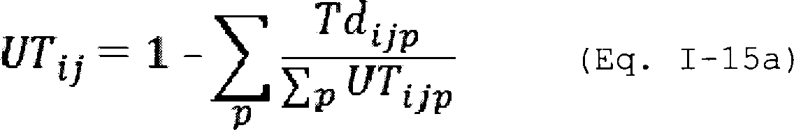
Where:
UTij = The average uptime factor of all abatement systems connected to process tools in the fab using input gas i in process sub-type or process type j (expressed as a decimal fraction).
Tdijp = The total time, in minutes, that abatement system p, connected to process tool(s) in the fab using input gas i in process sub-type or process type j, is not in operational mode, as defined in § 98.98, when at least one of the tools connected to abatement system p is in operation.
UTijp = Total time, in minutes per year, in which abatement system p has at least one associated tool in operation. For determining the amount of tool operating time, you may assume that tools that were installed for the whole of the year were operated for 525,600 minutes per year. For tools that were installed or uninstalled during the year, you must prorate the operating time to account for the days in which the tool was not installed; treat any partial day that a tool was installed as a full day (1,440 minutes) of tool operation. For an abatement system that has more than one connected tool, the tool operating time is 525,600 minutes per year if at least one tool was installed at all times throughout the year. If you have tools that are idle with no gas flow through the tool, you may calculate total tool time using the actual time that gas is flowing through the tool.
i = Input gas.
j = Process sub-type or process type.
p = Abatement system.
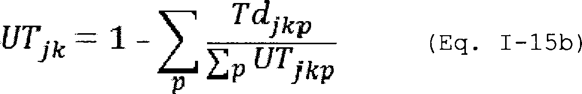
Where:
UTjk = The average uptime factor of all abatement systems connected to process tools in the fab which emit by-product gas k, in process sub-type or process type j (expressed as a decimal fraction).
Tdjkp = The total time, in minutes, that abatement system p, connected to process tool(s) in the fab which emit by-product gas k, in process sub-type or process type j, is not in operational mode, as defined in § 98.98, when at least one of the tools connected to abatement system p is in operation.
UTkp = Total time, in minutes per year, in which abatement system p has at least one associated tool in operation. For determining the amount of tool operating time, you may assume that tools that were installed for the whole of the year were operated for 525,600 minutes per year. For tools that were installed or uninstalled during the year, you must prorate the operating time to account for the days in which the tool was not installed; treat any partial day that a tool was installed as a full day (1,440 minutes) of tool operation. For an abatement system that has more than one connected tool, the tool operating time is 525,600 minutes per year if at least one tool was installed at all times throughout the year. If you have tools that are idle with no gas flow through the tool, you may calculate total tool time using the actual time that gas is flowing through the tool.
j = Process sub-type or process type.
k = By-product gas.
p = Abatement system.
(h) If you use fluorinated heat transfer fluids, you must calculate the annual emissions of fluorinated heat transfer fluids on a fab basis using the mass balance approach described in Equation I-16 of this subpart.
* * * * *EHi = Emissions of fluorinated heat transfer fluid i, on a fab basis (metric tons/year).
* * * * *IiB = Inventory of fluorinated heat transfer fluid i, on a fab basis, in containers other than equipment at the beginning of the reporting year (in stock or storage) (l). The inventory at the beginning of the reporting year must be the same as the inventory at the end of the previous reporting year.
Pi = Acquisitions of fluorinated heat transfer fluid i, on a fab basis, during the reporting year (l), including amounts purchased from chemical suppliers, amounts purchased from equipment suppliers with or inside of equipment, and amounts returned to the facility after off-site recycling.
Ni = Total nameplate capacity (full and proper charge) of equipment that uses fluorinated heat transfer fluid i and that is newly installed in the fab during the reporting year (l).
Ri = Total nameplate capacity (full and proper charge) of equipment that uses fluorinated heat transfer fluid i and that is removed from service in the fab during the reporting year (l).
IiE = Inventory of fluorinated heat transfer fluid i, on a fab basis in containers other than equipment at the end of the reporting year (in stock or storage)(l).
Di = Disbursements of fluorinated heat transfer fluid i, on a fab basis, during the reporting year, including amounts returned to chemical suppliers, sold with or inside of equipment, and sent off-site for verifiable recycling or destruction (l). Disbursements should include only amounts that are properly stored and transported so as to prevent emissions in transit.
* * * * *(i) Stack test method. As an alternative to the default emission factor method in paragraph (a) of this section, you may calculate fab-level fluorinated GHG emissions using fab-specific emission factors developed from stack testing. To use the method in this paragraph, you must first make a preliminary estimate of the fluorinated GHG emissions from each stack system in the fab under paragraph (i)(1) of this section. You must then compare the Start Printed Page 63580preliminary estimate for each stack system to the criteria in paragraph (i)(2) of this section to determine whether the stack system meets the criteria for using the stack test method described in paragraph (i)(3) of this section or whether the stack system meets the criteria for using the method described in paragraph (i)(4) of this section to estimate emissions from the stack systems that are not tested.
(1) Preliminary estimate of emissions by stack system in the fab. You must calculate a preliminary estimate of the annual emissions of each fluorinated GHG from each stack system in the fab using default utilization and by-product formation rates as shown in Table I-11, I-12, I-13, I-14, or I-15 of this subpart, as applicable, and by using Equations I-8 and I-9 of this subpart. When using Equations I-8 and I-9 of this subpart for the purposes of this paragraph (i)(1), you must also adhere to the procedures in paragraphs (i)(1)(i) to (iii) of this section to calculate preliminary estimates.
(i) When you are calculating preliminary estimates for the purpose of this paragraph (i)(1), you must consider the subscript “j” in Equations I-8 and I-9, and I-13 of this subpart to mean “stack system” instead of “process sub-type or process type.” For the value of aij, the fraction of input gas i that is used in tools with abatement systems, for use in Equations I-8 and I-9, you may use the ratio of the number of tools using input gas i that have abatement systems that are vented to the stack system for which you are calculating the preliminary estimate to the total number of tools using input gas i that are vented to that stack system, expressed as a decimal fraction. You may use this approach to determining aij only for this preliminary estimate.
(ii) You must use data from the previous reporting year to estimate the consumption of input gas i as calculated in Equation I-13 of this subpart and the fraction of input gas i destroyed in abatement systems for each stack system as calculated by Equation I-24 of this subpart. When calculating the consumption of input gas i as calculated in Equation I-13 of this subpart, the term “fij” is replaced with the ratio of the number of tools using input gas i that are vented to the stack system for which you are calculating the preliminary estimate to the total number of tools in the fab using input gas i, expressed as a decimal fraction. You may use this approach to determining fij only for this preliminary estimate.
(iii) You must use data from the previous reporting year to estimate the total uptime of all abatement systems for the stack system as calculated by Equation I-23 of this subpart, instead of using Equation I-15a or Equation I-15b of this subpart to calculate the average uptime factor.
(2) Method selection for stack systems in the fab. If the calculations under paragraph (i)(1) of this section, as well as any subsequent annual measurements and calculations under this subpart, indicate that the stack system meets the criteria in paragraph (i)(2)(i) through (iii) of this section, then you may comply with either paragraph (i)(3) of this section (stack test method) or paragraph (i)(4) of this section (method to estimate emissions from the stack systems that are not tested). If the stack system does not meet all three criteria in paragraph (i)(2)(i) through (iii) of this section, then you must comply with the stack test method specified in paragraph (i)(3) of this section.
(i) The sum of annual emissions of fluorinated GHGs from all of the combined stack systems that are not tested in the fab is less than 10,000 metric ton CO2 e per year. For those fluorinated GHG in Tables I-11, I-12, I-13, I-14, and I-15 of this subpart for which Table A-1 to subpart A of this part does not define a GWP value, you must use a value of 2,000 for the GWP in calculating metric ton CO2 e for that fluorinated GHG.
(ii) When all stack systems in the fab are ordered from lowest to highest emitting in metric ton CO2 e of fluorinated GHG per year, each of the stack systems that is not tested is within the set of the fab's lowest emitting fluorinated GHG stack systems that together emit 15 percent or less of total CO2 e fluorinated GHG emissions from the fab. For those fluorinated GHG that do not have GWP values listed in Table A-1 to subpart A of this part, you must use a GWP value of 2,000 in calculating CO2 e.
(iii) Fluorinated GHG emissions from each of the stack systems that is not tested can only be attributed to particular process tools during the test (that is, the stack system that is not tested cannot be used as an alternative emission point or bypass stack system from other process tools not attributed to the untested stack system).
(3) Stack system stack test method. For each stack system in the fab for which testing is required, measure the emissions of each fluorinated GHG from the stack system by conducting an emission test. In addition, measure the fab-specific consumption of each fluorinated GHG by the tools that are vented to the stack systems tested. Measure emissions and consumption of each fluorinated GHG as specified in § 98.94(j). Develop fab-specific emission factors and calculate fab-level fluorinated GHG emissions using the procedures specified in paragraph (i)(3)(i) through (viii) of this section. All emissions test data and procedures used in developing emission factors must be documented according to § 98.97.
(i) You must measure, and, if applicable, apportion the fab-specific fluorinated GHG consumption of the tools that are vented to the stack systems that are tested during the emission test as specified in § 98.94(j)(3). Calculate the consumption for each fluorinated GHG for the test period.
(ii) You must calculate the emission of each fluorinated GHG consumed as an input gas using Equation I-17 of this subpart and each fluorinated GHG formed as a by-product gas using Equation I-18 of this subpart and the procedures specified in paragraphs (i)(3)(ii)(A) through (E) of this section. If a stack system has more than one stack emitting to the atmosphere from a common header, you must measure the fluorinated GHG concentration and flow in each stack from that header to the atmosphere, and sum the emissions from each stack in the stack system when using Equation I-17 or Equation I-18 of this subpart.

Where:
Eis = Total fluorinated GHG input gas i, emitted from stack system s, during the sampling period (kg).
Xism = Average concentration of fluorinated GHG input gas i in stack system s, during the time interval m (ppmv).
MWi = Molecular weight of fluorinated GHG input gas i (g/g-mole).
Qs = Flow rate of the stack system s, during the sampling period (m3/min).Start Printed Page 63581
SV = Standard molar volume of gas (0.02240 m3/g-mole at 68 °F and 1 atm).
Δtm = Length of time interval m (minutes). Each time interval in the sampling period must be less than or equal to 60 minutes (for example an 8 hour sampling period would consist of at least 8 time intervals).
1/103 = Conversion factor (1 kilogram/1,000 grams).
i = Fluorinated GHG input gas.
s = Stack system.
N = Total number of time intervals m in sampling period.
m = Time interval.

Where:
Eks = Total fluorinated GHG by-product gas k, emitted from stack system s, during the sampling period (kg).
Xks = Average concentration of fluorinated GHG by-product gas k in stack system s, during the time interval m (ppmv).
MWk = Molecular weight of the fluorinated GHG by-product gas k (g/g-mole).
Qs = Flow rate of the stack system s, during the sampling period (m3/min).
SV = Standard molar volume of gas (0.02240 m3/g-mole at 68 °F and 1 atm).
Δtm = Length of time interval m (minutes). Each time interval in the sampling period must be less than or equal to 60 minutes (for example an 8 hour sampling period would consist of at least 8 time intervals).
1/103 = Conversion factor (1 kilogram/1,000 grams).
k = Fluorinated GHG by-product gas.
s = Stack system.
N = Total number of time intervals m in sampling period.
m = Time interval.
(A) If a fluorinated GHG is consumed during the sampling period, but emissions are not detected, use one-half of the field detection limit you determined for that fluorinated GHG according to § 98.94(j)(2) for the value of “Xism” in Equation I-17.
(B) If a fluorinated GHG is consumed during the sampling period and detected intermittently during the sampling period, use the detected concentration for the value of “Xism” in Equation I-17 when available and use one-half of the field detection limit you determined for that fluorinated GHG according to § 98.94(j)(2) for the value of “Xism” when the fluorinated GHG is not detected.
(C) If a fluorinated GHG is not consumed during the sampling period but is detected intermittently as a by-product gas, use the measured concentration for “Xksm” in Equation I-18 when available and use one-half of the field detection limit you determined for that fluorinated GHG according to § 98.94(j)(2) for the value of “Xksm” when the fluorinated GHG is not detected.
(D) If a fluorinated GHG is an expected by-product gas of the stack system tested and is not detected during the sampling period, use one-half of the field detection limit you determined for that fluorinated GHG according to § 98.94(j)(2) for the value of “Xksm” in Equation I-18.
(E) If a fluorinated GHG is not an expected by-product of the stack system and is not detected during the sampling period, then assume zero emissions for that fluorinated GHG for the tested stack system.
(iii) You must calculate a fab-specific emission factor for each fluorinated GHG input gas consumed (in kg of fluorinated GHG emitted per kg of input gas i consumed) in the tools that vent to stack systems that are tested, as applicable, using Equation I-19 of this subpart. If the emissions of input gas i exceed the consumption of input gas i during the sampling period, then equate “Eij” to the consumption of input gas i and treat the difference between the emissions and consumption of input gas i as a by-product of the other input gases, using Equation I-20 of this subpart.

Where:
EFif = Emission factor for fluorinated GHG input gas i, from fab f, representing 100 percent abatement system uptime (kg emitted/kg input gas consumed).
Eis = Mass emission of fluorinated GHG input gas i from stack system s, during the sampling period (kg emitted).
Activityif = Consumption of fluorinated GHG input gas i, for fab f, in the tools vented to the stack systems being tested, during the sampling period, as determined following the procedures specified in § 98.94(j)(3) (kg consumed).
UTf = The total uptime of all abatement systems for fab f, during the sampling period, as calculated in Equation I-23 of this subpart (expressed as decimal fraction). If the stack system does not have abatement systems on the tools vented to the stack system, the value of this parameter is zero.
aif = Fraction of fluorinated GHG input gas i used in fab f in tools with abatement systems (expressed as a decimal fraction).
dif = Fraction of fluorinated GHG input gas i destroyed or removed in abatement systems connected to process tools in fab f, as calculated in Equation I-24 of this subpart (expressed as decimal fraction). If the stack system does not have abatement systems on the tools vented to the stack system, the value of this parameter is zero.
f = Fab.
i = Fluorinated GHG input gas.
s = Stack system.
(iv) You must calculate a fab-specific emission factor for each fluorinated GHG formed as a by-product (in kg of fluorinated GHG per kg of total fluorinated GHG consumed) in the tools vented to stack systems that are tested, as applicable, using Equation I-20 of this subpart. When calculating the by-product emission factor for an input gas for which emissions exceeded its consumption, exclude the consumption of that input gas from the term “∑(Activityif).”
Start Printed Page 63582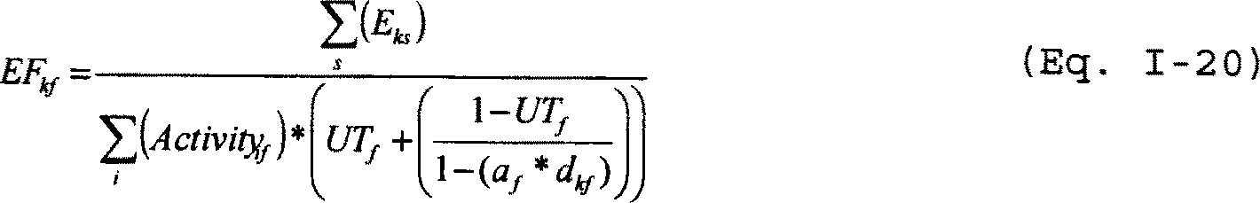
Where:
EFkf = Emission factor for fluorinated GHG by-product gas k, from fab f, (kg emitted/kg of all input gases consumed in tools vented to stack systems that are tested).
Eks = Mass emission of fluorinated GHG by-product gas k, emitted from stack system s, during the sampling period (kg emitted).
Activityif = Consumption of fluorinated GHG input gas i for fab f in tools vented to stack systems that are tested, during the sampling period as determined following the procedures specified in § 98.94(j)(3) (kg consumed).
UTf = The total uptime of all abatement systems for fab f, during the sampling period, as calculated in Equation I-23 of this subpart (expressed as decimal fraction).
af = Fraction of all input gases used in fab f in tools with abatement systems (expressed as a decimal fraction).
dkf = Fraction of fluorinated GHG by-product gas k destroyed or removed in abatement systems connected to process tools in fab f, as calculated in Equation I-24 of this subpart (expressed as decimal fraction).
f = Fab.
i = Fluorinated GHG input gas.
k = Fluorinated GHG by-product gas.
s = Stack system.
(v) You must calculate annual fab-level emissions of each fluorinated GHG consumed using Equation I-21 of this section.

Where:
Eif = Annual emissions of fluorinated GHG input gas i (kg/year) from the stack systems that are tested for fab f.
EFif = Emission factor for fluorinated GHG input gas i emitted from fab f, as calculated in Equation I-19 of this subpart (kg emitted/kg input gas consumed).
Cif = Total consumption of fluorinated GHG input gas i in tools that are vented to stack systems that are tested, for fab f, for the reporting year, as calculated using Equation I-13 of this subpart (kg/year).
UTf = The total uptime of all abatement systems for fab f, during the reporting year, as calculated using Equation I-23 of this subpart (expressed as a decimal fraction).
aif = Fraction of fluorinated GHG input gas i used in fab f in tools with abatement systems (expressed as a decimal fraction).
dif = Fraction of fluorinated GHG input gas i destroyed or removed in abatement systems connected to process tools in fab f that are included in the stack testing option, as calculated in Equation I-24 of this subpart (expressed as decimal fraction).
f = Fab.
i = Fluorinated GHG input gas.
(vi) You must calculate annual fab-level emissions of each fluorinated GHG by-product formed using Equation I-22 of this section.

Where:
Ekf = Annual emissions of fluorinated GHG by-product k (kg/year) from the stack systems that are tested for fab f.
EFkf = Emission factor for fluorinated GHG by-product k, emitted from fab f, as calculated in Equation I-20 of this subpart (kg emitted/kg of all input gases consumed).
Cif = Total consumption of fluorinated GHG input gas i in tools that are vented to stack systems that are tested, for fab f, for the reporting year, as calculated using Equation I-13 of this subpart.
UTf = The total uptime of all abatement systems for fab f, during the reporting year as calculated using Equation I-23 of this subpart (expressed as a decimal fraction).
af = Fraction of input gases used in fab f in tools with abatement systems (expressed as a decimal fraction).
dkf = Fraction of fluorinated GHG by-product k destroyed or removed in abatement systems connected to process tools in fab f that are included in the stack testing option, as calculated in Equation I-24 of this subpart (expressed as decimal fraction).
f = Fab.
i = Fluorinated GHG input gas.
k = Fluorinated GHG by-product.
(vii) When using the stack testing method described in this paragraph (i), you must calculate abatement system uptime on a fab basis using Equation I-23 of this subpart. When calculating abatement system uptime for use in Equation I-19 and I-20 of this subpart, you must evaluate the variables “Tdpj” and “UTpf” for the sampling period instead of the reporting year.
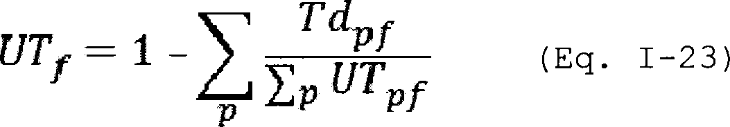
Where:
UTf = The total uptime of all abatement systems, for fab f (expressed as a decimal fraction).
Tdpf = The total time, in minutes, that abatement system p, connected to process tool(s) in fab f, is not in operational mode as defined in § 98.98.
UTpf = Total time, in minutes per year, in which the tool(s) connected at any point during the year to abatement system p, in fab f could be in operation. For determining the amount of tool operating time, you may assume that tools that were installed for the whole of the year were operated for 525,600 minutes per Start Printed Page 63583year. For tools that were installed or uninstalled during the year, you must prorate the operating time to account for the days in which the tool was not installed; treat any partial day that a tool was installed as a full day (1,440 minutes) of tool operation. For an abatement system that has more than one connected tool, the tool operating time is 525,600 minutes per year if there was at least one tool installed at all times throughout the year. If you have tools that are idle with no gas flow through the tool, you may calculate total tool time using the actual time that gas is flowing through the tool.
f = Fab.
p = Abatement system.
(viii) When using the stack testing option described in this paragraph (i), you must calculate the weighted average fraction of input gas i destroyed or removed in abatement systems for each fab f, as applicable, by using Equation I-24 of this subpart.

Where:
dif = The average weighted fraction of fluorinated GHG input gas i destroyed or removed in abatement systems in fab f (expressed as a decimal fraction).
Cijf = The amount of fluorinated GHG input gas i consumed for process type j fed into abatement systems in fab f (kg).
DREij = Destruction or removal efficiency for fluorinated GHG input gas i in abatement systems connected to process tools where process type j is used (expressed as a decimal fraction) determined according to § 98.94(f).
f = fab.
i = Fluorinated GHG input gas.
j = Process type.
(4) Method to calculate emissions from stack systems that are not tested. You must calculate annual fab-level emissions of each input and by-product fluorinated GHG for those fluorinated GHG listed in paragraphs (i)(4)(i) and (ii) of this section using default utilization and by-product formation rates as shown in Tables I-11, I-12, I-13, I-14, or I-15 of this subpart, as applicable, and by using Equations I-8, I-9, and I-13 of this subpart. When using Equations I-8, I-9, and I-13 of this subpart to fulfill the requirements of this paragraph, you must use, in place of the term Cij in each equation, the total consumption of each fluorinated GHG meeting the criteria in paragraph (i)(4)(i) of this section or that is used in tools vented to the stack systems that meet the criteria in paragraph (i)(4)(ii) of this section. You also must use the results of Equation I-24 of this subpart in place of the terms dij in Equation I-8 of this subpart and djk in Equation I-9 of this subpart, and use the results of Equation I-23 of this subpart in place of the results of Equation I-15a or Equation I-15b of this subpart for the terms UTij and UTjk.
(i) Calculate emissions from consumption of each intermittent low-use fluorinated GHG as defined in § 98.98 of this subpart using the default utilization and by-product formation rates and equations specified in paragraph (i)(4) of this section. If a fluorinated GHG was not being used during the stack testing and does not meet the definition of intermittent low-use fluorinated GHG in § 98.98, then you must test the stack systems associated with the use of that fluorinated GHG at a time when that gas is in use at a magnitude that would allow you to determine an emission factor for that gas according to the procedures specified in paragraph (i)(3) of this section.
(ii) Calculate emissions from consumption of each fluorinated GHG used in tools vented to stack systems that meet the criteria specified in paragraphs (i)(2)(i) through (i)(2)(iii) of this section, and were not tested according to the procedures in paragraph (i)(3) of this section. Calculate emissions using the default utilization and by-product formation rates and equations specified in paragraph (i)(4) of this section.
(5) To determine the total emissions of each fluorinated GHG from each fab under this stack testing option, you must sum the emissions of each fluorinated GHG determined from the procedures in paragraph (i)(3) of this section with the emissions of the same fluorinated GHG determined from the procedures in paragraph (i)(4) of this section.
7. Section 98.94 is amended by:
a. Removing and reserving paragraph (a).
b. Revising paragraph (b), paragraph (c) introductory text, and paragraph (c)(2).
c. Adding paragraph (c)(3).
d. Removing and reserving paragraphs (d) and (e).
e. Revising paragraph (f) introductory text and paragraph (f)(1) introductory text, (f)(1)(ii), (f)(2), (f)(3) and (f)(4).
f. Removing and reserving paragraphs (g)(1) and (g)(2).
g. Revising paragraphs (g)(3) and (g)(4).
h. Revising paragraph (h) introductory text and paragraphs (h)(3) and (i).
i. Adding paragraphs (j) and (k).
The additions and revisions read as follows:
Monitoring and QA/QC requirements.(a) [Reserved.]
(b) For purposes of Equation I-12 of this subpart, you must estimate fab-wide gas-specific heel factors for each container type for each gas used, except for fluorinated GHGs or N2 O which your fab uses in quantities less than 50 kg in one reporting year, according to the procedures in paragraphs (b)(1) through (b)(5) of this section.
(1) Base your fab-wide gas-specific heel factors on the trigger point for change out of a container for each container size and type for each gas used. Fab-wide gas-specific heel factors must be expressed as the ratio of the trigger point for change out, in terms of mass, to the initial mass in the container, as determined by paragraphs (b)(2) and (3) of this section.
(2) The trigger points for change out you use to calculate fab-wide gas-specific heel factors in paragraph (b)(1) of this section must be determined by monitoring the mass or the pressure of your containers. If you monitor the pressure, convert the pressure to mass using the ideal gas law, as displayed in Equation I-25 of this subpart, with the appropriate Z value selected based upon the properties of the gas.

Where:
p = Absolute pressure of the gas (Pa).
V = Volume of the gas container (m3).
Z = Compressibility factor.
n = Amount of substance of the gas (moles).
R = Gas constant (8.314 Joule/Kelvin mole).
T = Absolute temperature (K).
(3) The initial mass you use to calculate a fab-wide gas-specific heel factor in paragraph (b)(1) of this section may be based on the weight of the gas provided to you in gas supplier documents; however, you remain responsible for the accuracy of these masses and weights under this subpart.Start Printed Page 63584
(4) If a container is changed in an exceptional circumstance, as specified in paragraphs (b)(4)(i) and (ii) of this section, you must weigh that container or measure the pressure of that container with a pressure gauge, in place of using a heel factor to determine the residual weight of gas. When using mass-based trigger points for change out, you must determine if an exceptional circumstance has occurred based on the net weight of gas in the container, excluding the tare weight of the container.
(i) For containers with a maximum storage capacity of less than 9.08 kg (20 lbs) of gas, an exceptional circumstance is a change out point that differs by more than 50 percent from the trigger point for change out used to calculate your fab-wide gas-specific heel factor for that gas and container type.
(ii) For all other containers, an exceptional circumstance is a change out point that differs by more than 20 percent from the trigger point for change out used to calculate your fab-wide gas-specific heel factor for that gas and container type.
(5) You must re-calculate a fab-wide gas-specific heel factor if you execute a process change to modify the trigger point for change out for a gas and container type that differs by more than 5 percent from the previously used trigger point for change out for that gas and container type.
(c) You must develop apportioning factors for fluorinated GHG and N2 O consumption (including the fraction of gas consumed by process tools connected to abatement systems as in Equations I-8, I-9, I-10, and I-24 of this subpart), to use in the equations of this subpart for each input gas i, process sub-type, process type, stack system, and fab as appropriate, using a fab-specific engineering model that is documented in your site GHG Monitoring Plan as required under § 98.3(g)(5). This model must be based on a quantifiable metric, such as wafer passes or wafer starts, or direct measurement of input gas consumption as specified in paragraph (c)(3) of this section. To verify your model, you must demonstrate its precision and accuracy by adhering to the requirements in paragraphs (c)(1) and (2) of this section.
* * * * *(2) You must demonstrate the accuracy of your fab-specific model by comparing the actual amount of input gas i consumed and the modeled amount of input gas i consumed in the fab, as follows:
(i) You must analyze actual and modeled gas consumption for a period when the fab is at a representative operating level (as defined in § 98.98) lasting at least 30 days but no more than the reporting year.
(ii) You must compare the actual gas consumed to the modeled gas consumed for one fluorinated GHG reported under this subpart for the fab. You must certify that the fluorinated GHG selected for comparison corresponds to the largest quantity, on a mass basis, of fluorinated GHG consumed at the fab during the reporting year for which you are required to apportion following the procedures specified in § 98.93(a), (b), or (i). You may compare the actual gas consumed to the modeled gas consumed for two fluorinated GHGs and demonstrate conformance according to paragraph (c)(2)(iii) of this section on an aggregate use basis for both fluorinated GHGs if one of the fluorinated GHGs selected for comparison corresponds to the largest quantities, on a mass basis, of fluorinated GHGs used at each fab during the reporting year.
(iii) You must demonstrate that the comparison performed for the largest quantity of gas(es), on a mass basis, consumed in the fab in paragraph (c)(2)(ii) of this section, does not result in a difference between the actual and modeled gas consumption that exceeds 20 percent relative to actual gas consumption, reported to two significant figures using standard rounding conventions.
(iv) If you are required to apportion gas consumption and use the procedures in § 98.93(i) to calculate annual emissions from a fab, you must verify your apportioning factors using the procedures in paragraphs (c)(2)(ii) and (iii) of this section such that the time period specified in paragraph (c)(2)(i) of this section ends on the last day you perform the sampling events specified under § 98.93(i)(3).
(v) If your facility has multiple fabs with a single centralized fluorinated-GHG supply system and two or more fabs that use different methods to calculate annual emissions of fluorinated GHGs, you must verify that your apportioning model can apportion fluorinated GHG consumption among the fabs by adhering to the procedures in paragraphs (c)(2)(ii) through (c)(2)(iv) of this section.
(3) As an alternative to developing apportioning factors for fluorinated GHG and N2 O consumption using a fab-specific engineering model, you may develop apportioning factors through the use of direct measurement using gas flow meters and weigh scales to measure process sub-type, process type, stack system, or fab-specific input gas consumption. You may use a combination of apportioning factors developed using a fab-specific engineering model and apportioning factors developed through the use of direct measurement, provided this is documented in your site GHG Monitoring Plan as required under 98.3(g)(5).
* * * * *(f) You must adhere to the procedures in paragraphs (f)(1) and (f)(2) of this section if your facility employs abatement systems and you use § 98.93(a) and/or § 98.93(b) to calculate emissions and wish to reflect emission reductions due to these systems. You must also adhere to the procedures in paragraphs (f)(1) and (f)(2) of this section if you use § 98.93(i) to calculate emissions. If you use the default destruction or removal efficiencies in Table I-16 of this subpart, you must adhere to procedures in paragraph (f)(3) of this section. If you use an average of properly measured destruction or removal efficiencies for a gas and process sub-type or process type combination, as applicable, during a reporting year, you must adhere to procedures in paragraph (f)(4) of this section.
(1) You must certify and document that the abatement systems are properly installed, operated, and maintained according to manufacturers' specifications by adhering to the procedures in paragraphs (f)(1)(i) and (ii) of this section.
* * * * *(ii) You must certify and document your abatement systems are operated and maintained in accordance with the manufacturers' specifications and according to the site maintenance plan for abatement systems that is developed and maintained in your records as specified in § 98.97(d).
(2) You must calculate and document the uptime of abatement systems using Equations I-15a, I-15b, or I-23 of this subpart, as applicable.
(3) To report emissions using the default destruction or removal efficiencies in Table I-16 of this subpart, you must certify and document that the abatement systems at your facility are specifically designed for fluorinated GHG and N2 O abatement.
(4) If you do not use the default destruction or removal efficiency values to calculate and report controlled emissions, you must use an average of properly measured destruction or removal efficiencies for each gas and process sub-type or process type combination, as applicable, determined in accordance with procedures in paragraphs (f)(4)(i) through (vi) of this Start Printed Page 63585section. You must not use a default value from Table I-16 of this subpart for any gas and process type combination for which you have measured the destruction or removal efficiency according to the requirements of paragraphs (f)(4)(i) through (vi) of this section.
(i) A properly measured destruction or removal efficiency value must be determined in accordance with EPA 430-R-10-003 (incorporated by reference, see § 98.7), or according to an alternative method approved by the Administrator as specified in paragraph (k) of this section. If you are measuring destruction or removal efficiency according to EPA 430-R-10-003, you may follow the alternative procedures specified in Appendix A to this subpart.
(ii) You must select and properly measure the destruction or removal efficiency for a random sample of abatement systems to include in a random sampling abatement system testing program in accordance with procedures in paragraphs (f)(4)(ii)(A) and (B) of this section.
(A) For the first 2 years for which your fab is required to report emissions of fluorinated GHG and N2 O, for each abatement system gas and process sub-type or process type combination, as applicable, a random sample of 10 percent of installed abatement systems must be tested annually for a total of 20 percent, or 20 percent may be tested in the first year. For every 3-year period following the initial 2-year period, a random sample of 15 percent of installed abatement systems must be tested for each gas and process sub-type or process type combination; you may test 15-percent in the first year of the 3-year period, but you must test at least 5 percent each year until 15 percent are tested. If the required percent of the total number of abatement systems to be tested for each gas and process sub-type or process type combination does not equate to a whole number, the number of systems to be tested must be determined by rounding up to the nearest integer.
(B) If testing of a randomly selected abatement system would be disruptive to production, you may replace that system with another randomly selected system for testing and return the system to the sampling pool for subsequent testing. Any one abatement system must not be replaced by another randomly selected system for more than three consecutive selections. When you have to replace a system in one year, you may select that specific system to be tested in one of the next two sampling years so that you may plan testing of that abatement system to avoid disrupting production.
(iii) You must use default destruction or removal efficiencies for a gas and process type combination, until you complete testing on 20 percent of the abatement systems for that gas and process sub-type or process type combination, as applicable. Following testing on 20 percent of abatement systems for that gas and process sub-type or process type combination, you must calculate the average destruction or removal efficiency as the arithmetic mean of all test results for that gas and process sub-type or process type combination, until you have tested at least 30 percent of all abatement systems for each gas and process sub-type or process type combination. After testing at least 30 percent of all systems for a gas and process sub-type or process type combination, you must use the arithmetic mean of the most recent 30 percent of systems tested as the average destruction or removal efficiency.
(iv) If a measured destruction or removal efficiency is below the manufacturer-claimed fluorinated GHG or N2 O destruction or removal efficiency and the abatement system is installed, operated, and maintained in accordance with the manufacturers' specifications, the measured destruction or removal efficiency must be included in the calculation of the destruction or removal efficiency value for that gas and process sub-type or process type, as applicable.
(v) If a measured destruction or removal efficiency is below the manufacturer-claimed fluorinated GHG or N2 O destruction or removal efficiency and the abatement system is not installed, operated, or maintained in accordance with the manufacturers' specifications, you must implement corrective action and perform a retest to replace the measured value within the reporting year. In lieu of retesting within the reporting year, you may use the measured value in calculating the average destruction or removal efficiency for the reporting year, and then include the same system in the next year's abatement system testing in addition to the testing of randomly selected systems for that next reporting year.
(vi) If your fab uses redundant abatement systems, you may account for the total abatement system uptime calculated for a specific exhaust stream during the reporting year.
(g) * * *
(3) Follow the QA/QC procedures in accordance with those in EPA 430-R-10-003 (incorporated by reference, see § 98.7), or the applicable QA/QC procedures specified in an alternative method approved by the Administrator according to paragraph (k) of this section, when calculating abatement systems destruction or removal efficiencies. If you are measuring destruction or removal efficiency according to EPA 430-R-10-003, and you elect to follow the alternative procedures specified in Appendix A to this subpart according to paragraph (f)(4)(i) of this section, you must follow any additional QA/QC procedures specified in Appendix A to this subpart.
(4) Demonstrate that, as part of normal operations for each fab, the inventory of gas stored in containers at the beginning of the reporting year is the same as the inventory of gas stored in containers at the end of the previous reporting year.
(h) You must adhere to the QA/QC procedures of this paragraph (h) when calculating annual gas consumption for each fluorinated GHG and N2 O used at each fab and emissions from the use of each fluorinated heat transfer fluid on a fab basis.
* * * * *(3) Ensure that the inventory at the beginning of one reporting year is identical to the inventory reported at the end of the previous reporting year.
* * * * *(i) All flowmeters, weigh scales, pressure gauges, and thermometers used to measure quantities that are monitored under this section or used in calculations under § 98.93 must meet the calibration and accuracy requirements specified in § 98.3(i).
(j) Stack test methodology. For each fab for which you calculate annual emissions for any fluorinated GHG emitted from your facility using the stack test method according to the procedure specified in § 98.93(i)(3), you must adhere to the requirements in paragraphs (j)(1) through (8) of this section. You may request approval to use an alternative stack test method and procedure according to paragraph (k) of this section.
(1) Stack system testing. Conduct an emissions test for each applicable stack system according to the procedures in paragraphs (j)(1)(i) through (iv) of this section.
(i) You must conduct an emission test during which the fab is operating at a representative operating level, as defined in § 98.98, and with the abatement systems connected to the stack system being tested operating with at least 90 percent uptime during the 8-hour (or longer) period for each stack system, or at no less than 90 percent of the abatement system uptime rate Start Printed Page 63586measured over the previous reporting year.
(ii) You must measure for tetrafluoromethane (CF4), hexafluoroethane (C2 F6) and any other fluorinated GHG expected to be emitted from the stack system and those fluorinated GHGs used as input fluorinated GHG in process tools vented to the stack system, except for any intermittent low-use fluorinated GHG as defined in § 98.98. You must calculate annual emissions of intermittent low-use fluorinated GHGs by adhering to the procedures in § 98.93(i)(4).
(iii) You must determine the fluorinated GHGs expected to be emitted from the stack system based on a documented facility analysis of all fluorinated GHGs consumed and emitted in the previous reporting year, and all fluorinated GHGs expected to be consumed and emitted in the current reporting year by process tools vented to the stack system. You must also include in that analysis any possible fluorinated GHG by-products formed from fluorinated GHGs consumed in the previous reporting year and expected to be consumed in the current reporting year by process tools connected to the stack system. In developing your facility analysis, you must also consider all fluorinated GHG by-products listed in Tables I-3 through I-7 of this subpart, as applicable, to the products manufactured at your facility. If a fluorinated GHG being consumed in the reporting year was not being consumed during the stack testing and does not meet the definition of intermittent low-use fluorinated GHG in § 98.98, then you must test the stack systems associated with the use of that fluorinated GHG at a time when that gas is in use at a magnitude that would allow you to determine an emission factor for that gas. If a fluorinated GHG consumed in the reporting year was not being consumed during the stack testing and is no longer in use by your fab (e.g., use of the gas has become obsolete or has been discontinued), then you must calculate annual emissions for that fluorinated GHG according to the procedure specified in § 98.93(i)(4).
(iv) Although all applicable stack systems are not required to be tested simultaneously, you must certify that no changes in stack flow configuration (including, for example, the number and type of tools vented to each stack system) occur between tests conducted for any particular fab in a reporting year.
(2) Test methods and procedures. You must adhere to the applicable test methods and procedures specified in Table I-9 to this subpart, or adhere to an alternative method approved by the Administrator according to paragraph (k) of this section. The field detection limits achieved under your test methods and procedures must fall at or below the maximum field detection limits specified in Table I-10 to this subpart.
(3) Fab-specific fluorinated GHG consumption measurements. You must determine the amount of each fluorinated GHG consumed by each fab during the sampling period for all process tools connected to the stack systems tested under § 98.93(i)(3), according to the procedures in paragraphs (j)(3)(i) and (ii) of this section. This determination must include apportioning gas consumption between stack systems that are being tested and those that not tested under § 98.93(i)(2).
(i) Measure fluorinated GHG consumption using gas flow meters, scales, or pressure measurements. Measure the mass or pressure, as applicable, at the beginning and end of the sampling period and when containers are changed out. If you elect to measure gas consumption using pressure (i.e., because the gas is stored in a location above its critical temperature) you must estimate consumption as specified in paragraphs (j)(i)(A) and (B) of this section.
(A) For each fluorinated GHG, you must either measure the temperature of the fluorinated GHG container(s) when the sampling periods begin and end and when containers are changed out, or measure the temperature of the fluorinated GHG container(s) every hour for the duration of the sampling period. Temperature measurements of the immediate vicinity of the containers (e.g., in the same room, near the containers) shall be considered temperature measurements of the containers.
(B) Convert the sampling period-beginning, sampling period-ending, and container change-out pressures to masses using Equation I-25 of this subpart, with the appropriate Z value selected based upon the properties of the gas (e.g., the Z value yielded by the Redlich, Kwong, Soave equation of state with appropriate values for that gas). Apply the temperatures measured at or nearest to the beginning and end of the sampling period and to the time(s) when containers are changed out, as applicable. For each gas, the consumption during the sampling period is the difference between the masses of the containers of that gas at the beginning and at the end of the sampling period, summed across containers, including containers that are changed out.
(ii) For each fluorinated GHG gas for which consumption is too low to be accurately measured during the sampling period using gas flow meters, scales, or pressure measurements as specified in paragraph (j)(3)(i) of this section, you must follow at least one of the procedures listed in paragraph (j)(3)(ii)(A) through (C) of this section to obtain a consumption measurement.
(A) Draw the gas from a single gas container if it is normally supplied from multiple containers connected by a shared manifold.
(B) Calculate consumption from pro-rated long-term consumption data (for example, calculate and use hourly consumption rates from monthly consumption data).
(C) Increase the duration of the sampling period for consumption measurement beyond the minimum duration specified in Table I-9 of this subpart.
(4) Emission test results. The results of an emission test must include the analysis of samples, number of test runs, the average emission factor for each fluorinated GHG measured, the analytical method used, calculation of emissions, the fluorinated GHGs consumed during the sampling period, an identification of the stack systems tested, and the fluorinated GHGs that were included in the test. The emissions test report must contain all information and data used to derive the fab-specific emission factor.
(5) Emissions testing frequency. You must conduct emissions testing to develop fab-specific emission factors on a frequency according to the procedures in paragraph (j)(5)(i) or (ii) of this section.
(i) Annual testing. You must conduct an annual emissions test for each stack system for which emissions testing is required under § 98.93(i)(3), unless you meet the criteria in paragraph (j)(5)(ii) of this section to skip annual testing. Each set of emissions testing for a stack system must be separated by a period of at least 2 months.
(ii) Criteria to test less frequently. After the first 3 years of annual testing, you may calculate the relative standard deviation of the emission factors for each fluorinated GHG included in the test and use that analysis to determine the frequency of any future testing. As an alternative, you may conduct all three tests in less than 3 calendar years for purposes of this paragraph (j)(5)(ii), but this does not relieve you of the obligation to conduct subsequent annual testing if you do not meet the criteria to test less frequently. If the criteria specified in paragraphs (j)(5)(ii)(A) and (B) of this section are met, you may use Start Printed Page 63587the arithmetic average of the three emission factors for each fluorinated GHG and fluorinated GHG by-product for the current year and the next 4 years with no further testing unless your fab operations are changed in way that triggers the re-test criteria in paragraph (j)(8) of this section. In the fifth year following the last stack test included in the previous average, you must test each of the stack systems for which testing is required and repeat the relative standard deviation analysis using the results of the most recent three tests. If the criteria specified in paragraphs (j)(5)(ii)(A) and (B) of this section are not met, you must use the emission factors developed from the most recent testing and continue annual testing. You may conduct more than one test in the same year, but each set of emissions testing for a stack system must be separated by a period of at least 2 months. You may repeat the relative standard deviation analysis using the most recent three tests to determine if you are exempt from testing for the next 4 years.
(A) The relative standard deviation of the total CO2 e emission factors calculated from each of the three tests (expressed as the total CO2 e fluorinated GHG emissions of the fab divided by the total CO2 e fluorinated GHG use of the fab) is less than or equal to 15 percent.
(B) The relative standard deviation for all single fluorinated GHGs that individually accounted for 5 percent or more of CO2 e emissions were less than 20 percent.
(C) For those fluorinated GHG that do not have GWP values listed in Table A-1 to subpart A of this part, you must use a GWP value of 2,000 in calculating CO2 e in paragraphs (j)(5)(ii)(A) and (B) of this section.
(6) Subsequent measurements. You must make an annual determination of each stack system's exemption status under § 98.93(i)(2) by March 31 each year. If a stack system that was previously not required to be tested per § 98.93(i)(2), no longer meets the criteria in § 98.93(i)(2), you must conduct the emissions testing for the stack system during the current reporting and develop the fab-specific emission factor from the emissions testing.
(7) Previous measurements. You may include the results of emissions testing conducted after [DATE 3 YEARS BEFORE DATE OF PUBLICATION OF FINAL RULE] for use in the relative standard deviation calculation in paragraph (j)(5)(ii) of this section if the previous results were determined using a method meeting the requirements in paragraph (j)(2) of this section.
(8) Scenarios that require a stack system to be re-tested. By March 31 of each reporting year, you must evaluate and determine whether any changes to your fab operations meet the criteria specified in paragraphs (j)(8)(i) through (vi) of this section. If any of the scenarios specified in paragraph (j)(8)(i) through (vi) of this section occur, you must perform a re-test of any applicable stack system, irrespective of whether you have met the criteria for less frequent testing in paragraph (j)(5)(ii) of this section, before the end of the year in which the evaluation was completed. You must adhere to the methods and procedures specified in § 98.93(i)(3) for performing a stack system emissions test and calculating emissions. If you meet the criteria for less frequent testing in paragraph (j)(5)(ii) of this section, and you are required to perform a re-test as specified in paragraph (j)(8)(i) through (vi) of this section, the requirement to perform a re-test does not extend the date of the next scheduled test that was established prior to meeting the requirement to perform a re-test. If the criteria specified in paragraph (j)(5)(ii) of this section are not met using the results from the re-test and the two most recent stack tests, you must use the emission factors developed from the most recent testing to calculate emissions and resume annual testing. You may resume testing less frequently according to your original schedule if the criteria specified in paragraph (j)(5)(ii) of this section are met using the most recent three tests.
(i) Annual consumption of a fluorinated GHG used during the most recent emissions test (expressed in CO2 e) changes by more than 10 percent of the total annual fluorinated GHG consumption, relative to gas consumption in CO2 e for that gas during the year of the most recent emissions test (for example, if the use of a single gas goes from 25 percent of CO2 e to greater than 35 percent of CO2 e, this change would trigger a re-test). For those fluorinated GHG that do not have GWP values listed in Table A-1 to subpart A of this part, you must use a GWP value of 2,000 in calculating CO2 e.
(ii) A change in the consumption of an intermittent low-use fluorinated GHG (as defined in § 98.98) that was not used during the emissions test and not reflected in the fab-specific emission factor, such that it no longer meets the definition of an intermittent low-use fluorinated GHG.
(iii) A decrease by more than 10 percent in the fraction of tools with abatement systems, compared to the number during the most recent emissions test.
(iv) A change in the wafer size manufactured by the fab since the most recent emissions test.
(v) A stack system that formerly met the criteria specified under § 98.93(i)(2) for not being subject to testing no longer meets those criteria.
(vi) A gas is used or emitted that meets the criteria in paragraph (j)(1)(iii) of this section.
(k) You may request approval to use an alternative stack test method and procedure or to use an alternative method to determine abatement system destruction or removal efficiency by adhering to the requirements in paragraphs (k)(1) through (k)(6) of this section. An alternative method is any method of sampling and analyzing for a fluorinated GHG or N2 O, or the determination of parameters other than concentration, for example, flow measurements, that is not a method specified in this subpart and that has been demonstrated to the Administrator's satisfaction, using Method 301 in appendix A of part 63, to produce results adequate for the Administrator's determination that it may be used in place of a method specified elsewhere in this subpart.
(1) You may use an alternative method from that specified in this subpart provided that you:
(i) Notify the Administrator of your intention to use an alternative method. You must include in the notification a site-specific test plan describing the alternative method and procedures (the alternative test plan), the range of test conditions over which the validation is intended to be applicable, and an alternative means of calculating the fab-level fluorinated GHG or N2 O emissions or determining the abatement system destruction or removal efficiency if the Administrator denies the use of the results of the alternative method under paragraph (k)(2) or (3) of this section.
(ii) Use Method 301 in appendix A of part 63 of this chapter to validate the alternative method. This may include the use of only portions of specific procedures of Method 301 if use of such procedures are sufficient to validate the alternative method; and
(iii) Submit the results of the Method 301 validation process along with the notification of intention and the rationale for not using the specified method.
(2) The Administrator will determine whether the validation of the proposed alternative method is adequate and issue an approval or disapproval of the alternative test plan within 120 days of the date on which you submit the notification and alternative test plan specified in paragraph (k)(1) of this Start Printed Page 63588section. If the Administrator approves the alternative test plan, you are authorized to use the alternative method(s) in place of the methods described in paragraph (f)(4)(i) of this section for measuring destruction or removal efficiency or paragraph (j) of this section for conducting the stack test, as applicable, taking into account the Administrator's comments on the alternative test plan. Notwithstanding the requirement in the preceding sentence, you may at any time prior to the Administrator's approval or disapproval proceed to conduct the stack test using the methods specified in paragraph (j) of this section or the destruction or removal efficiency determination specified in (f)(4)(i) of this section if you use a method specified in this subpart instead of the requested alternative.
(3) You must report the results of stack testing or destruction or removal efficiency determination using the alternative method and procedure specified in the approved alternative test plan. You must include in your report for an alternative stack test method and for an alternative abatement system destruction or removal efficiency determination the information specified in paragraph (j)(4) of this section, including all methods, calculations and data used to determine the fluorinated GHG emission factor or the abatement system destruction or removal efficiency. The Administrator will review the results of the test using the alternative methods and procedure and then approve or deny the use of the results of the alternative test method and procedure no later than 120 days after they are submitted to EPA.
(4) If the Administrator finds reasonable grounds to dispute the results obtained by an alternative method for the purposes of determining fluorinated GHG emissions or destruction or removal efficiency of an abatement system, the Administrator may require the use of another method specified in this subpart.
(5) Once the Administrator has approved the use of the alternative method for the purposes of determining fluorinated GHG emissions for specific fluorinated GHGs and types of stack systems or abatement system destruction or removal efficiency, that method may be used at any other facility for the same fluorinated GHGs and types of stack systems, or fluorinated GHGs and abatement systems, if the approved conditions apply to that facility. In granting approval, the Administrator may limit the range of test conditions and emission characteristics for which that approval is granted and under which the alternative method may be used without seeking approval under paragraphs (k)(1) through (4) of this section. The Administrator will specify those limitations, if any, in the approval of the alternative method.
(6) Neither the validation and approval process nor the failure to validate or obtain approval of an alternative method shall abrogate your responsibility to comply with the requirements of this subpart.
8. Section 98.96 is amended by:
a. Revising paragraph (c) introductory text and paragraphs (c)(1), (c)(2), and (c)(3).
b. Adding paragraph (c)(5).
c. Removing and reserving paragraphs (f), (g), (h), (i), (j), (k), and (l).
d. Revising paragraph (m) introductory text, redesignating paragraphs (m)(i) through (m)(iv) as paragraphs (m)(1) through (m)(4), and revising new paragraphs (m)(1), (m)(3) and (m)(4).
e. Adding paragraph (m)(5).
f. Removing and reserving paragraphs (n) and (o).
g. Revising paragraph (p).
h. Revising paragraphs (q), (r), and (s).
i. Removing and reserving paragraphs (t) and (v).
j. Adding paragraphs (w), (x) and (y).
The additions and revisions read as follows:
Data reporting requirements.* * * * *(c) Annual emissions, on a fab basis as described in paragraph (c)(1) through (5) of this section.
(1) When you use the procedures specified in § 98.93(a) of this subpart, each fluorinated GHG emitted from each process type for which your fab is required to calculate emissions as calculated in Equations I-6 and I-7 of this subpart.
(2) Each fluorinated GHG emitted from each process type or process sub-type as calculated in Equations I-8 and I-9 of this subpart, as applicable.
(3) N2 O emitted from all chemical vapor deposition processes and N2 O emitted from the aggregate of other N2 O-using manufacturing processes as calculated in Equation I-10 of this subpart.
* * * * *(5) When you use the procedures specified in § 98.93(i) of this subpart, annual emissions of each fluorinated GHG, on a fab basis.
* * * * *(m) For the fab-specific apportioning model used to apportion fluorinated GHG and N2 O consumption under § 98.94(c), the following information to determine it is verified in accordance with procedures in § 98.94(c)(1) and (2):
(1) Identification of the quantifiable metric used in your fab-specific engineering model to apportion gas consumption for each fab.
* * * * *(3) Certification that the gas(es) you selected under § 98.94(c)(2)(ii) for each fab corresponds to the largest quantity(ies) consumed on a mass basis, of fluorinated GHG used at your fab during the reporting year for which you are required to apportion.
(4) The result of the calculation comparing the actual and modeled gas consumption under § 98.94(c)(2)(iii) and (iv), as applicable.
(5) If you are required to apportion fluorinated GHG consumption between fabs as required by § 98.94(c)(2)(v), certification that the gas(es) you selected under § 98.94(c)(2)(ii) corresponds to the largest quantity(ies) consumed on a mass basis, of fluorinated GHG used at your facility during the reporting year for which you are required to apportion.
* * * * *(p) Inventory and description of all abatement systems through which fluorinated GHGs or N2 O flow at your facility and for which you are claiming destruction or removal efficiency, including:
(1) The number of abatement systems controlling emissions for each process sub-type, or process type, as applicable, for each gas used in the process sub-type or process type.
(2) The basis of the destruction or removal efficiency being used (default or site specific measurement according to § 98.94(f)(4)(i)) for each process sub-type or process type and for each gas.
(q) For all abatement systems through which fluorinated GHGs or N2 O flow at your facility, for which you are reporting controlled emissions, a certification that all abatement systems at the facility have been installed, maintained, and operated in accordance with the manufacturer's specifications and according to the site maintenance plan for abatement systems that is developed and maintained in your records as specified in § 98.97(d).
(r) You must report an effective facility-wide destruction or removal efficiency value calculated using Equation I-26, I-27, and I-28 of this subpart, as appropriate. For those fluorinated GHG for which Table A-1 to subpart A of this part does not define a GWP value, you must use a value of 2,000 for the GWP in calculating metric ton CO2 e for that fluorinated GHG.
Start Printed Page 63589
Where:
DREFAC = Facility-wide effective destruction or removal efficiency value, expressed as a decimal fraction.
FGHGi = Total emissions of each fluorinated GHG i emitted from electronics manufacturing processes in the facility, calculated according to the procedures in § 98.93.
N2 Oj = Emissions of N2 O from each N2 O-emitting electronics manufacturing process j in the facility, expressed in metric ton CO2 equivalents, calculated according to the procedures in § 98.93.
UAFGHG = Total unabated emissions of fluorinated GHG emitted from electronics manufacturing processes in the facility, expressed in metric ton CO2 equivalents as calculated in Equation I-27 of this subpart.
SFGHG = Total unabated emissions of fluorinated GHG emitted from electronics manufacturing processes in the facility, expressed in metric ton CO2 equivalents, as calculated in Equation I-28 of this subpart.
CN2O,j = Consumption of N2 O in each N2 O emitting process j, expressed in metric ton CO2 equivalents.
1-UN2O,j = N2 O emission factor for each N2 O emitting process j from Table I-8 of this subpart.
GWPi = GWP of emitted fluorinated GHG i from Table A-1 of this part. For those fluorinated GHGs for which Table A-1 to subpart A of this part does not define a GWP value, use a GWP value of 2,000.
GWPN2O = GWP of N2 O from Table A-1 of this part.
i = Fluorinated GHG.
j = Process Type.
(1) Use Equation I-27 of this subpart to calculate total unabated emissions, in metric tons CO2 e, of all fluorinated GHG emitted from electronics manufacturing processes whose emissions of fluorinated GHG you calculated according to the default utilization and by-product formation rate procedures in § 98.93(a) or § 98.93(i)(4). For each fluorinated GHG i in process j, use the same consumption (Cij), emission factors (1-Uij), and by-product formation rates (Bijk) to calculate unabated emissions as you used to calculate emissions in § 98.93(a) or § 98.93(i)(4). For those fluorinated GHGs for which Table A-1 to subpart A of this part does not define a GWP value, use a GWP value of 2,000.

Where:
UAFGHG = Total unabated emissions of fluorinated GHG i emitted from electronics manufacturing processes in the facility, expressed in metric ton CO2 e for which you calculated total emission according to the procedures in § 98.93(a) or § 98.93(i)(4).
Cij = Total consumption of fluorinated GHG i, apportioned to process j, expressed in metric ton CO2 e for which you used to calculate total emissions according to the procedures in § 98.93(a) or § 98.93(i)(4).
Uij = Process utilization rate for fluorinated GHG i, process type j, for which you used to calculate total emissions according to the procedures in § 98.93(a) or § 98.93(i)(4).
GWPi = GWP of emitted fluorinated GHG i from Table A-1 of this part. For those fluorinated GHGs for which Table A-1 to subpart A of this part does not define a GWP value, use a GWP value of 2,000.
GWPk = GWP of emitted fluorinated GHG by-product k, from Table A-1 of this part. For those fluorinated GHGs for which Table A-1 to subpart A of this part does not define a GWP value, use a GWP value of 2,000.
Bijk = By-product formation rate of fluorinated GHG k created as a by-product per amount of fluorinated GHG input gas i (kg) consumed by process type j (kg).
i = Fluorinated GHG.
j = Process Type.
k = Fluorinated GHG by-product.
(2) Use Equation I-28 to calculate total unabated emissions, in metric ton CO2 e, of all fluorinated GHG emitted from electronics manufacturing processes whose emissions of fluorinated GHG you calculated according to the stack testing procedures in § 98.93(i)(3). For each set of processes, use the same input gas consumption (Cif), input gas emission factors (EFif), by-product gas emission factors (EFkf), fractions of tools abated (aif and af), and destruction efficiencies (dkf and dkf) to calculate unabated emissions as you used to calculate emissions. For those fluorinated GHGs for which Table A-1 to subpart A of this part does not define a GWP value, use a GWP value of 2,000.

Where:
SFGHG = Total unabated emissions of fluorinated GHG i emitted from electronics manufacturing processes in the facility, expressed in metric ton CO2 e for which you calculated total emission according to the procedures in § 98.93(i)(3).
EFif = Emission factor for fluorinated GHG input gas i, emitted from fab f, as calculated in Equation I-19 of this subpart (kg emitted/kg input gas consumed).
aif = Fraction of fluorinated GHG input gas i used in fab f in tools with abatement systems (expressed as a decimal fraction).
dif = Fraction of fluorinated GHG i destroyed or removed in abatement systems connected to process tools in fab f, for which you used to calculate total emissions according to the procedures in § 98.93(i)(3) (expressed as a decimal fraction).
Cif = Total consumption of fluorinated GHG input gas i, of tools vented to stack systems that are tested, for fab f, for the reporting year, expressed in metric ton CO2 e for which you used to calculate total emissions according to the procedures in § 98.93(i)(3) (expressed as a decimal fraction).
EFkf = Emission factor for fluorinated GHG by-product gas k, emitted from fab f, as Start Printed Page 63590calculated in Equation I-20 of this subpart (kg emitted/kg of all input gas consumed in tools vented to stack systems that are tested).
af = Fraction of all input gas used in fab f in tools with abatement systems (expressed as a decimal fraction).
dkf = Fraction of fluorinated GHG by-product k destroyed or removed in abatement systems connected to process tools in fab f, for which you used to calculate total emissions according to the procedures in § 98.93(i)(3) (expressed as a decimal fraction).
Uij = Process utilization rate for fluorinated GHG i, process type j, for which you used to calculate total emissions according to the procedures in § 98.93(a) or § 98.93(i)(4).
GWPi = GWP of emitted fluorinated GHG i from Table A-1 of this part. For those fluorinated GHGs for which Table A-1 of subpart A to this part does not define a GWP value, use a GWP value of 2,000.
GWPk = GWP of emitted fluorinated GHG by-product k, from Table A-1 of this part. For those fluorinated GHGs for which Table A-1 to subpart A of this part does not define a GWP value, use a GWP value of 2,000.
i = Fluorinated GHG.
j = Process Type.
k = Fluorinated GHG by-product.
(s) Where missing data procedures were used to estimate inputs into the fluorinated heat transfer fluid mass balance equation under § 98.95(b), the number of times missing data procedures were followed in the reporting year and the method used to estimate the missing data.
* * * * *(w) If you elect to calculate fab-level emissions of fluorinated GHG using the stack test method specified in § 98.93(i), you must report the following in paragraphs (w)(1) and (2) for each stack system, in addition to the relevant data in paragraphs (a) through (v) of this section:
(1) The date of any stack testing conducted during the reporting year, and the identity of the stack system tested.
(2) An inventory of all stack systems from which process fluorinated GHG are emitted. For each stack system, indicate whether the stack system is among those for which stack testing was performed as per § 98.93(i)(3) or not performed as per § 98.93(i)(2).
(x) If the emissions you report under paragraph (c) of this section include emissions from research and development activities, as defined in § 98.6, report the approximate percentage of total GHG emissions, on a metric ton CO2 e basis, that are attributable to research and development activities, using the following ranges: less than 5 percent, 5 percent to less than 10 percent, 10 percent to less than 25 percent, 25 percent to less than 50 percent, 50 percent and higher. For those fluorinated GHG that do not have GWP values listed in Table A-1 of subpart A of this part, you must use a GWP value of 2,000 in calculating CO2 e.
(y) If your semiconductor manufacturing facility emits more than 40,000 metric ton CO2 e of GHG emissions, based on your most recently submitted annual report (beginning with the 2015 reporting year) as required in paragraph (c) of this section, from the electronics manufacturing processes subject to reporting under this subpart, you must prepare and submit a triennial (every 3 years) technology assessment report to the Administrator that meets the requirements specified in paragraphs (y)(1) through (6) of this section. Any other semiconductor manufacturing facility may voluntarily submit this report to the Administrator.
(1) The first report must be submitted with the annual GHG emissions report that is due no later than March 31, 2017, and subsequent reports must be delivered every 3 years no later than March 31 of the year in which it is due.
(2) The report must include the information described in paragraphs (y)(2)(i) through (v) of this section.
(i) It must describe how the gases and technologies used in semiconductor manufacturing using 200 mm and 300 mm wafers in the United States have changed in the past 3 years and whether any of the identified changes are likely to have affected the emissions characteristics of semiconductor manufacturing processes in such a way that the default utilization and by-product formation rates or default destruction or removal efficiency values may need to be updated.
(ii) It must describe the effect on emissions of the implementation of new process technologies and/or finer line width processes in 200 mm and 300 mm technologies, the introduction of new tool platforms, and the introduction of new processes on previously tested platforms.
(iii) It must describe the status of implementing 450 mm wafer technology and the potential need to create or update default emission factors compared to 300 mm technology.
(iv) It must provide any default utilization and by-product formation rates and/or destruction or removal efficiency data that have been collected in the previous 3 years that support the changes in semiconductor manufacturing processes described in the report.
(v) It must describe the use of a new gas, use of an existing gas in a new process type or sub-type, or a fundamental change in process technology.
(3) If, on the basis of the information reported in paragraph (y)(2) of this section, the report indicates that GHG emissions from semiconductor manufacturing may have changed from those represented by the default utilization and by-product formation rates in Tables I-3, I-4, or I-5, or the default destruction or removal efficiency values in Table I-16 of this subpart, the report must lay out a data gathering and analysis plan focused on the areas of potential change. The plan must describe:
(i) The testing of tools to determine the potential effect on current default utilization and by-product formation rates and destruction or removal efficiency values under the new conditions, and
(ii) A planned analysis of the effect on overall facility emissions using a representative gas-use profile for a 200 mm, 300 mm, or 450 mm fab (depending on which technology is under consideration).
(4) Multiple semiconductor manufacturing facilities may submit a single consolidated 3-year report as long as the facility identifying information in § 98.3(c)(1) and the certification statement in § 98.3(c)(9) is provided for each facility for which the consolidated report is submitted.
(5) The Administrator will review the report received and determine whether it is necessary to update the default utilization rates and by-product formation rates in Tables I-3 through I-7 and I-11 through I-15 of this subpart and default destruction or removal efficiency values based on the following:
(i) Whether the revised default utilization and by-product formation rates and destruction or removal efficiency values will result in a projected shift in emissions of 10 percent or greater.
(ii) Whether new platforms, processes, or facilities that are not captured in current default utilization and by-product formation rates and destruction or removal efficiency values should be included in revised values.
(iii) Whether new data are available that could expand the existing data set to include new gases, tools, or processes not included in the existing data set (i.e. gases, tools, or processes for which no data are currently available).
(6) The Administrator will review the reports within 120 days and will notify you of its determination whether it is Start Printed Page 63591necessary to update any default utilization and by-product formation rates and/or destruction or removal efficiency values. If the Administrator determines it is necessary to update default utilization and by-product formation rates and/or destruction or removal efficiency values, you will then have 180 days from the date you receive notice of the determination to execute the data collection and analysis plan described in the report and submit those data to the Administrator.
9. Section 98.97 is amended by:
a. Removing and reserving paragraph (b).
b. Revising paragraph (c).
c. Revising paragraph (d) introductory text and paragraph (d)(1).
d. Adding paragraphs (d)(1)(i) through (d)(1)(iii).
e. Removing and reserving paragraph (d)(3).
f. Revising paragraph (d)(4).
g. Adding paragraphs (d)(5) through (d)(9).
h. Adding paragraphs (i) through (s).
The revisions read as follows:
Records that must be retained.* * * * *(c) Documentation for the fab-specific engineering model used to apportion fluorinated GHG and N2 O consumption. This documentation must be part of your site GHG Monitoring Plan as required under § 98.3(g)(5). At a minimum, you must retain the following:
(1) A clear, detailed description of the fab-specific model, including how it was developed; the quantifiable metric used in the model; all sources of information, equations, and formulas, each with clear definitions of terms and variables; all apportioning factors used to apportion fluorinated GHG and N2 O; and a clear record of any changes made to the model while it was used to apportion fluorinated GHG and N2 O consumption across process sub-types, process types, tools with and without abatement systems, stack systems, and/or fabs.
(2) Sample calculations used for developing the gas apportioning factors (fij) for the two fluorinated GHGs used at your facility in the largest quantities, on a mass basis, during the reporting year.
(3) If you develop apportioning factors through the use of direct measurement according to § 98.94(c)(3), calculations and data used to develop each gas apportioning factor.
(4) Calculations and data used to determine and document that the fab was operating at representative operating levels, as defined in § 98.98, during the apportioning model verification specified in § 98.94(c).
(d) For all abatement systems through which fluorinated GHGs or N2 O flow at your facility, and for which you are reporting controlled emissions, the following in paragraphs (d)(1) to (9) of this section:
(1) Records of the information in paragraphs (d)(1)(i) though (iii) of this section:
(i) Documentation to certify that each abatement system is installed, maintained, and operated in accordance with manufacturers' specifications.
(ii) Documentation from the abatement system supplier describing the abatement system's designed purpose and emission control capabilities for fluorinated GHG and N2 O.
(iii) Certification that the abatement systems for which emissions are being reported were specifically designed for fluorinated GHG and N2 O abatement.
* * * * *(4) Where properly measured site-specific destruction or removal efficiencies are used to report emissions, the information in paragraphs (d)(4)(i) though (vi) of this section:
(i) Dated certification by the technician who made the measurement that the destruction or removal efficiency is calculated in accordance with methods in EPA 430-R-10-003 (incorporated by reference, see § 98.7) and, if applicable Appendix A of this subpart, or an alternative method approved by the Administrator as specified in § 98.94(k), complete documentation of the results of any initial and subsequent tests, the final report as specified in EPA 430-R-10-003 (incorporated by reference, see § 98.7) and, if applicable, the records and documentation specified in Appendix A of this subpart including the information required in paragraph (b)(7) of Appendix A of this subpart, or a final report as specified in an alternative method approved by the Administrator as specified in § 98.94(k).
(ii) The average destruction or removal efficiency of the abatement systems operating during the reporting year for each process type and gas combination.
(iii) A description of the calculation used to determine the average destruction or removal efficiency for each process type and gas combination, including all inputs to the calculation.
(iv) The records of destruction or removal efficiency measurements for abatement systems for all tests that have been used to determine the site-specific destruction or removal efficiencies currently being used.
(v) A description of the method used for randomly selecting abatement systems for testing.
(vi) The total number of systems for which destruction or removal efficiency was properly measured for each process type and gas combination for the reporting year.
(5) In addition to the inventory in § 98.96(p), the information in paragraphs (d)(5)(i) though (iii) of this section:
(i) The number of abatement systems of each manufacturer, and model numbers, and the manufacturer's claimed fluorinated GHG and N2 O destruction or removal efficiency, if any.
(ii) Records of destruction or removal efficiency measurements over the in-use life of each abatement system.
(iii) A description of the tool, with the process type or sub-type, for which the abatement system treats exhaust.
(6) Records of all inputs and results of calculations made accounting for the uptime of abatement systems used during the reporting year, in accordance with Equations I-15a, I-15b, or I-23 of this subpart, as applicable. The inputs should include an indication of whether each value for destruction or removal efficiency is a default value or a measured site-specific value.
(7) Records of all inputs and results of calculations made to determine the average weighted fraction of each gas destroyed or removed in the abatement systems for each stack system using Equation I-24 of this subpart, if applicable. The inputs should include an indication of whether each value for destruction or removal efficiency is a default value or a measured site-specific value.
(8) Records of all inputs and the results of the calculation of the facility-wide emission destruction or removal efficiency factor calculated according to Equation I-26 of this subpart.
(9) A maintenance plan for abatement systems, which includes a defined preventative maintenance process and checklist (built on the manufacturer's recommended maintenance program) and a corrective action process that you must follow whenever an abatement system is found to be not operating properly. The maintenance plan must be maintained on-site at the facility as part of the facility's GHG Monitoring Plan as described in § 98.3(g)(5).
* * * * *(i) Retain the following records for each stack system for which you elect to calculate fab-level emissions of fluorinated GHG using the procedures specified in § 98.93(i)(3) or (4).
(1) Document all stack systems with emissions of fluorinated GHG that are Start Printed Page 63592less than 10,000 metric tons of CO2 e per year and all stack systems with emissions of 10,000 metric tons CO2 e per year or more. Include the data and calculation used to develop the preliminary estimate of emissions for each stack system.
(2) For each stack system, identify the method used to calculate annual emissions; either § 98.93(i)(3) or (4).
(3) The emissions test data and reports (see § 98.94(j)(4)) and the calculations used to determine the fab-specific emission factor, including the actual fab-specific emission factor, the average hourly emission rate of each fluorinated GHG from the stack system during the test and the stack system activity rate during the test.
(4) The fab-specific emission factor and the calculations and data used to determine the fab-specific emission factor for each fluorinated GHG and by-product, as calculated using Equations I-19 and I-20 of § 98.93(i)(3).
(5) Calculations and data used to determine annual emissions of each fluorinated GHG for each fab.
(6) Calculations and data used to determine and document that the fab was operating at representative operating levels, as defined in § 98.98, during the stack testing period.
(7) A copy of the certification that no changes in stack system flow configuration occurred between tests conducted for any particular fab in a reporting year as required by § 98.94(j)(1)(iv) and any calculations and data supporting the certification.
(j) If you report the approximate percentage of total GHG emissions from research and development activities under § 98.96(x), documentation for the determination of the percentage of total emissions of each fluorinated GHG and/or N2 O attributable to research and development, as defined in § 98.6, activities.
(k) Annual gas consumption for each fluorinated GHG and N2 O as calculated in Equation I-11 of this subpart, including where your fab used less than 50 kg of a particular fluorinated GHG or N2 O used at your facility for which you have not calculated emissions using Equations I-6, I-7, I-8, I-9, I-10, I-21, or I-22 of this subpart, the chemical name of the GHG used, the annual consumption of the gas, and a brief description of its use.
(l) All inputs used to calculate gas consumption in Equation I-11 of this subpart, for each fluorinated GHG and N2 O used.
(m) Annual amount of each fluorinated GHG consumed for process sub-type, process type, stack system, or fab, as appropriate, and the annual amount of N2 O consumed for the chemical vapor deposition processes and from the aggregate of other electronics manufacturing production processes, as calculated using Equation I-13 of this subpart.
(n) Disbursements for each fluorinated GHG and N2 O during the reporting year, as calculated using Equation I-12 of this subpart and all inputs used to calculate disbursements for each fluorinated GHG and N2 O used in Equation I-12 of this subpart, including all fab-wide gas-specific heel factors used for each fluorinated GHG and N2 O. If your fab used less than 50 kg of a particular fluorinated GHG during the reporting year, fab-wide gas-specific heel factors do not need to be reported for those gases.
(o) Fraction of each fluorinated GHG or N2 O fed into a process sub-type, process type, stack system, or fab that is fed into tools connected to abatement systems.
(p) Fraction of each fluorinated GHG or N2 O destroyed or removed in abatement systems connected to process tools where process sub-type, process type j is used, or to process tools vented to stack system j or fab f.
(q) All inputs and results of calculations made accounting for the uptime of abatement systems used during the reporting year, or during an emissions sampling period, in accordance with Equations I-15a, I-15b and/or I-23 of this subpart, as applicable.
(r) For fluorinated heat transfer fluid emissions, inputs to the fluorinated heat transfer fluid mass balance equation, Equation I-16 of this subpart, for each fluorinated heat transfer fluid used.
(s) Where missing data procedures were used to estimate inputs into the fluorinated heat transfer fluid mass balance equation under § 98.95(b), the estimates of those data.
10. Section 98.98 is amended by:
a. Removing the definitions of “Class,” “Individual recipe,” and “Similar, with respect to recipes.”
b. Adding a definition for “Fab,” “Fully Fluorinated GHGs,” “Input gas,” “Intermittent low-use fluorinated GHG,” “Representative operating levels,” and “Stack system.”
c. Revising the definitions of “By-product formation,” “Gas utilization,” “Operational mode,” “Process types,” “Properly measured destruction or removal efficiency,” “Trigger point for change out,” “Uptime,” and “Wafer passes.”
d. Revising the definition of “Maximum designed substrate starts” to “Maximum substrate starts.”
The revisions read as follows:
End Part End Supplemental InformationDefinitions.* * * * *By-product formation means the creation of fluorinated GHGs during electronics manufacturing production processes or the creation of fluorinated GHGs by an abatement system. Where the procedures in § 98.93(a) are used to calculate annual emissions, by-product formation is the ratio of the mass of the by-product formed to the mass flow of the input gas. Where the procedures in § 98.93(i) are used to calculate annual emissions, by-product formation is the ratio of the mass of the by-product formed to the total mass flow of all input fluorinated GHGs.
* * * * *Fab means the portion of an electronics manufacturing facility located in a separate physical structure that began manufacturing on a certain date.
* * * * *Fully Fluorinated GHGs means fluorinated GHGs that contain only single bonds and in which all available valence locations are filled by fluorine atoms. This includes, but is not limited to, saturated perfluorocarbons, SF6, NF3, SF5 CF3, C4 F8 O, fully fluorinated linear, branched, and cyclic alkanes, fully fluorinated ethers, fully fluorinated tertiary amines, fully fluorinated aminoethers, and perfluoropolyethers.
Gas utilization means the fraction of input N2 O or fluorinated GHG converted to other substances during the etching, deposition, and/or wafer and chamber cleaning processes. Gas utilization is expressed as a rate or factor for specific electronics manufacturing process sub-types or process types.
* * * * *Input gas means a fluorinated GHG or N2 O used in one of the processes described in § 98.90(a)(1) through (4).
Intermittent low-use fluorinated GHG, for the purposes of determining fluorinated GHG emissions using the stack testing option, means a fluorinated GHG that meets all of the following:
(1) The fluorinated GHG is used by the fab but is not used during the period of stack testing for the fab/stack system.
(2) The emissions of the fluorinated GHG, estimated using the methods in § 98.93(i)(4) do not constitute more than 5 percent of the total fluorinated GHG emissions from the fab on a CO2 e basis.
(3) The sum of the emissions of all fluorinated GHGs that are considered intermittent low-use gases does not exceed 10,000 metric tons CO2 e for the fab for that year, as calculated using the procedures specified in § 98.93(i)(1) of this subpart.Start Printed Page 63593
Maximum substrate starts means for the purposes of Equation I-5 of this subpart, the maximum quantity of substrates, expressed as surface area, that could be started each month during a reporting year based on the equipment installed in that facility and assuming that the installed equipment were fully utilized. Manufacturing equipment is considered installed when it is on the manufacturing floor and connected to required utilities.
* * * * *Operational mode means the time in which an abatement system is properly installed, maintained, and operated according to manufacturers' specifications as required in § 98.93(f)(1). This includes being properly operated within the range of parameters as specified in the operations manual provided by the system manufacturer.
* * * * *Process types are broad groups of manufacturing steps used at a facility associated with substrate (e.g., wafer) processing during device manufacture for which fluorinated GHG emissions and fluorinated GHG consumption is calculated and reported. The process types are Plasma etching/Wafer Cleaning and Chamber cleaning.
Properly measured destruction or removal efficiency means destruction or removal efficiencies measured in accordance with EPA 430-R-10-003 (incorporated by reference, see § 98.7), and, if applicable, Appendix A to this subpart, or by an alternative method approved by the Administrator as specified in § 98.94(k).
* * * * *Representative operating levels means (for purposes of verification of the apportionment model or for determining the appropriate conditions for stack testing) operating the fab, in terms of substrate starts for the period of testing or monitoring, at no less than 50 percent of installed production capacity or no less than 70 percent of the average production rate for the reporting year, where production rate for the reporting year is represented in average monthly substrate starts. For the purposes of stack testing, the period for determining the representative operating level must be the period ending on the same date on which testing is concluded.
Stack system means one or more stacks that are connected by a common header or manifold, through which a fluorinated GHG-containing gas stream originating from one or more fab processes is, or has the potential to be, released to the atmosphere. For purposes of this subpart, stack systems do not include emergency vents or bypass stacks through which emissions are not usually vented under typical operating conditions.
Trigger point for change out means the residual weight or pressure of a gas container type that a facility uses as an indicator that operators need to change out that gas container with a full container. The trigger point is not the actual residual weight or pressure of the gas remaining in the cylinder that has been replaced.
Uptime means the ratio of the total time during which the abatement system is in an operational mode, to the total time during which production process tool(s) connected to that abatement system are normally in operation.
* * * * *Wafer passes is a count of the number of times a wafer substrate is processed in a specific process sub-type, or type. The total number of wafer passes over a reporting year is the number of wafer passes per tool multiplied by the number of operational process tools in use during the reporting year.
* * * * *11. Table I-1 to subpart I is amended by revising the footnote to read as follows:
Table I-1 to Subpart I of Part 98—Default Emission Factors for Threshold Applicability Determination
* * * * *Notes:
NA denotes not applicable based on currently available information.
12. Table I-3 to subpart I is revised to read as follows:
Table I-3 to Subpart I of Part 98—Default Emission Factors (1-Uij) for Gas Utilization Rates (Uij) and By-Product Formation Rates (Bijk) for Semiconductor Manufacturing for 150 mm and 200 mm Wafer Sizes
Process type/ sub-type Process gas i CF4 C2 F6 CHF3 CH2 F2 C2 HF5 CH3 F C3 F8 C4 F8 NF3 SF6 C4 F6 C5 F8 C4 F8 O ETCHING/WAFER CLEANING 1-Ui 0.81 0.76 0.50 0.13 0.064 0.66 NA 0.14 0.20 0.55 0.17 NA NA BCF4 NA 0.10 0.085 0.081 0.077 NA NA 0.12 0.0040 0.15 0.13 NA NA BC2 F6 0.048 NA 0.031 0.025 0.024 NA NA 0.037 NA 0.17 0.11 NA NA BC4 F6 NA NA NA NA NA NA NA NA NA NA NA NA NA BC4 F8 NA NA NA NA NA NA NA NA NA NA NA NA NA BC3 F8 NA NA NA NA NA NA NA NA NA NA NA NA NA BCHF3 0.11 NA NA 0.066 NA NA NA NA NA NA 0.066 NA NA CHAMBER CLEANING In situ plasma cleaning 1-Ui 0.92 0.55 NA NA NA NA 0.40 0.10 0.18 NA NA NA 0.14 BCF4 NA 0.21 NA NA NA NA 0.20 0.11 0.050 NA NA NA 0.13 BC2 F6 NA NA NA NA NA NA NA NA NA NA NA NA 0.045 BC3 F8 NA NA NA NA NA NA NA NA NA NA NA NA NA Remote plasma cleaning 1-Ui NA NA NA NA NA NA NA NA 0.018 NA NA NA NA BCF4 NA NA NA NA NA NA NA NA 0.015 NA NA NA NA BC2 F6 NA NA NA NA NA NA NA NA NA NA NA NA NA BC3 F8 NA NA NA NA NA NA NA NA NA NA NA NA NA Start Printed Page 63594 In situ thermal cleaning 1-Ui NA NA NA NA NA NA NA NA NA NA NA NA NA BCF4 NA NA NA NA NA NA NA NA NA NA NA NA NA BC2 F6 NA NA NA NA NA NA NA NA NA NA NA NA NA BC3 F8 NA NA NA NA NA NA NA NA NA NA NA NA NA Notes: NA denotes not applicable based on currently available information. 13. Table I-4 to subpart I is revised to read as follows:
Table I-4 to Subpart I of Part 98—Default Emission Factors (1-Uij) for Gas Utilization Rates (Uij) and By-Product Formation Rates (Bijk) for Semiconductor Manufacturing for 300 mm and 450 mm Wafer Size
Process type/sub-type Process gas i CF4 C2 F6 CHF3 CH2 F2 C3 F8 C4 F8 NF3 SF6 C4 F6 C5 F8 C4 F8 O ETCHING/WAFER CLEANING 1-Ui 0.63 0.80 0.39 0.15 NA 0.17 0.17 0.23 0.18 0.13 NA BCF4 NA 0.21 0.10 0.059 NA 0.046 0.052 0.045 0.066 0.15 NA BC2 F6 0.092 NA 0.078 0.068 NA 0.030 0.057 0.067 0.090 0.083 NA BC4 F6 NA NA 0.00010 NA NA 0.018 NA NA NA NA NA BC4 F8 0.00063 NA 0.00080 NA NA NA NA NA NA NA NA BC3 F8 NA NA NA NA NA NA NA NA NA NA NA BCHF3 0.011 NA NA 0.052 NA 0.028 0.035 NA 0.022 0.010 NA CHAMBER CLEANING In situ plasma cleaning 1-Ui NA NA NA NA NA NA 0.23 NA NA NA NA BCF4 NA NA NA NA NA NA 0.037 NA NA NA NA BC2 F6 NA NA NA NA NA NA NA NA NA NA NA BC3 F8 NA NA NA NA NA NA NA NA NA NA NA Remote plasma cleaning 1-Ui NA NA NA NA 0.063 NA 0.018 NA NA NA NA BCF4 NA NA NA NA NA NA 0.075 NA NA NA NA BC2 F6 NA NA NA NA NA NA NA NA NA NA NA BC3 F8 NA NA NA NA NA NA NA NA NA NA NA In situ thermal cleaning 1-Ui NA NA NA NA NA NA 0.28 NA NA NA NA BCF4 NA NA NA NA NA NA 0.010 NA NA NA NA BC2 F6 NA NA NA NA NA NA NA NA NA NA NA BC3 F8 NA NA NA NA NA NA NA NA NA NA NA Notes: NA denotes not applicable based on currently available information. 14. Table I-5 to subpart I is amended by revising the entries for “CVD 1-Ui,” “CVD BCF4” and “CVD BC3 F8;” and by revising the footnote to read as follows:
Table I-5 to Subpart I of Part 98—Default Emission Factors (1-Uij) for Gas Utilization Rates (Uij) and By-Product Formation Rates (Bijk) for MEMS Manufacturing
Process type factors Process gas i CF4 C2 F6 CHF3 CH2 F2 C3 F8 c-C4 F8 NF3 Remote NF3 SF6 C4 F6a C5 F8a C4 F8 Oa Etch 1-Ui 0.7 a 0.4 a 0.4 a 0.06 NA a 0.2 NA 0.2 0.2 0.1 0.2 NA Start Printed Page 63595 Etch BCF4 NA a 0.4 a 0.07 a 0.08 NA 0.2 NA NA NA a 0.3 0.2 NA Etch BC2 F6 NA NA NA NA NA 0.2 NA NA NA a 0.2 0.2 NA CVDChamber Cleaning 1-Ui 0.9 0.6 NA NA 0.4 0.1 0.02 0.2 NA NA 0.1 0.1 CVD Chamber Cleaning BCF4 NA 0.1 NA NA 0.1 0.1 b 0.02 b 0.1 NA NA 0.1 0.1 CVD Chamber Cleaning BC3 F8 NA NA NA NA NA NA NA NA NA NA NA 0.4 Notes: NA denotes not applicable based on currently available information. a Estimate includes multi-gas etch processes. b Estimate reflects presence of low-k, carbide and multi-gas etch processes that may contain a C-containing fluorinated GHG additive. 15. Table I-6 to subpart I is amended by revising the entries for “CVD 1-Ui” and by revising the footnote to read as follows:
Table I-6 to Subpart I of Part 98—Default Emission Factors (1-Uij) for Gas Utilization Rates (Uij) and By-Product Formation Rates (Bijk) for LCD Manufacturing
Process type factors Process gas i CF4 C2 F6 CHF3 CH2 F2 C3 F8 c-C4 F8 NF3 Remote NF3 SF6 * * * * * * * CVD Chamber Cleaning 1-Ui NA NA NA NA NA NA 0.03 0.3 0.9 Notes: NA denotes not applicable based on currently available information. 16. Table I-7 to subpart I is amended by revising the entries for “CVD 1-Ui” and “CVD BCF4;” and by revising the footnote to read as follows:
Table I-7 to Subpart I of Part 98—Default Emission Factors (1-Uij) for Gas Utilization Rates (Uij) and By-Product Formation Rates (Bijk) for PV Manufacturing
Process type factors Process gas i CF4 C2 F6 CHF3 CH2 F2 C3 F8 c-C4 F8 NF3 Remote NF3 SF6 * * * * * * * CVD Chamber Cleaning 1-Ui NA 0.6 NA NA 0.1 0.1 NA 0.3 0.4 CVD Chamber Cleaning BCF4 NA 0.2 NA NA 0.2 0.1 NA NA NA Notes: NA denotes not applicable based on currently available information. 17. Table I-8 to subpart I is amended by revising the entry for “Other Manufacturing Process 1-Ui” to read as follows:
Table I-8 to Subpart I of Part 98—Default Emission Factors (1-UN2O,j) for N2 O Utilization (UN2O,j)
Process type factors N2 O * * * * * Other Manufacturing Process 1-Ui 1.14 18. Subpart I is amended by adding Table I-9 to subpart I to read as follows: Start Printed Page 63596
Table I-9 to Subpart I of Part 98—Methods and Procedures for Conducting Emissions Tests for Stack Systems
For each stack system for which you use the stack test method to calculate annual emissions * * * You must * * * Using * * * For each fluorinated GHG Measure the concentration in the stack system Method 320 at 40 CFR part 63, appendix A. Conduct the test run for a minimum of 8 hours for each stack system. Select sampling port locations and the number of traverse points Method 1 or 1A at 40 CFR part 60, appendix A-1. Determine gas velocity and volumetric flow rate Method 2, 2A, 2C, 2D, 2F, or 2G at 40 CFR part 60, appendix A-1 and A-2. Determine gas molecular weight Method 3, 3A, or 3B at 40 CFR part 60, appendix A-2 using the same sampling site and time as fluorinated GHG sampling. Measure gas moisture content Method 4 at 40 CFR part 60, appendix A-3, or using FTIR.a a Extractive FTIR is an acceptable method, in lieu of Method 4 at 40 CFR part 60 appendix A, of determining the volumetric concentrations of moisture in semiconductor stack gas streams. The spectral calibrations employed should bracket the anticipated range of optical depths (H2 O concentration in parts per million multiplied by FTIR sample cell path length) measured in the field for moisture saturated (relative humidity approximately 100 percent) air streams at temperatures characterized via Method 2 at 40 CFR part 60 appendix A, within the stack. The HITRAN molecular spectroscopic database is an example of a widely used international standard of IR absorption parameters that provide accurate H2 O FTIR calibrations at atmospheric conditions. Field measurements should be verified to be in line with moisture saturated wet scrubber exhaust concentrations at measured temperatures; the use of a hygrometer can provide verification of accuracy, which must be ±2 percent. Field measurements should be verified to be consistent with published water vapor pressure curves at the current stack temperatures (Perry, R.H. and D.W. Green. Perry's Chemical Engineer's Handbook (8th Edition). McGraw-Hill Publishing Company, Inc. New Your, New York. 2008). The use of a hygrometer can also be used to provide verification of accuracy. 19. Subpart I is amended by adding Table I-10 to subpart I to read as follows:
Table I-10 to Subpart I of Part 98—Maximum Field Detection Limits Applicable to Fluorinated GHG Concentration Measurements for Stack Systems
Fluorinated GHG analyte Maximum field detection limit (ppbv) CF4 5 C2 F6 5 C3 F8 5 C4 F6 5 C5 F8 5 c-C4 F8 5 CH2 F2 10 CH3 F 10 CHF3 5 NF3 5 SF6 1 Other fully fluorinated GHGs 5 Other fluorinated GHGs 10 ppbv—Parts per billion by volume. Subpart I is amended by adding Table I-11 to subpart I to read as follows:
20. Subpart I is amended by adding Table I-11 to subpart I to read as follows:
Start Printed Page 63597Table I-11 to Subpart I of Part 98—Default Emission Factors (1-UIJ) for Gas Utilization Rates (UIJ) and By-Product Formation Rates (BIJK) for Semiconductor Manufacturing for Use With the Stack Test Method
[150 mm and 200 mm wafers]
All processes Process gas i CF4 C2 F6 CHF3 CH2 F2 C2 HF5 CH3 F C3 F8 C4 F8 NF3 SF6 C4 F6 C5 F8 C4 F8 O 1-Ui 0.81 0.71 0.50 0.13 0.064 0.66 0.40 0.14 0.19 0.55 0.17 NA 0.14 BCF4 NA 0.13 0.085 0.081 0.077 NA 0.20 0.12 0.021 0.15 0.13 NA 0.13 BC2 F6 0.048 NA 0.031 0.025 0.024 NA NA 0.037 NA .17 0.11 NA 0.045 BC4 F6 NA NA NA NA NA NA NA NA NA NA NA NA NA BC4 F8 NA NA NA NA NA NA NA NA NA NA NA NA NA BC3 F8 NA NA NA NA NA NA NA NA NA NA NA NA NA BCHF3 0.11 NA NA 0.066 NA NA NA NA NA NA 0.066 NA NA Notes: NA denotes not applicable based on currently available information. 21. Subpart I is amended by adding Table I-12 to subpart I to read as follows:
Table I-12 to Subpart I of Part 98-Default Emission Factors (1-UIJ) for Gas Utilization Rates (UIJ) and By-Product Formation Rates (BIJK) for Semiconductor Manufacturing for Use With the Stack Test Method
[300 mm and 450 mm wafer sizes]
All process Process gas i CF4 C2 F6 CHF3 CH2 F2 C3 F8 C4 F8 NF3 SF6 C4 F6 C5 F8 C4 F8 O 1-Ui 0.63 0.80 0.39 0.15 0.063 0.17 0.17 0.23 0.18 0.13 NA BCF4 NA 0.21 0.10 0.059 NA 0.046 0.062 0.045 0.066 0.15 NA BC2 F6 0.092 NA 0.078 0.068 NA 0.030 0.057 0.067 0.090 0.083 NA BC4 F6 NA NA 0.00010 NA NA 0.018 NA NA NA NA NA BC4 F8 0.00063 NA 0.00080 NA NA NA NA NA NA NA NA BC3 F8 NA NA NA NA NA NA NA NA NA NA NA BCHF3 0.011 NA NA 0.052 NA 0.028 0.035 NA 0.022 0.010 NA Notes: NA denotes not applicable based on currently available information. 22. Subpart I is amended by adding Table I-13 to subpart I to read as follows:
Table I-13 to Subpart I of Part 98—Default Emission Factors (1-UIJ) for Gas Utilization Rates (UIJ) and By-Product Formation Rates (BIJK) for LCD Manufacturing for Use With the Stack Test Method
Process gas (i) Process gas i CF4 C2 F6 CHF3 CH2 F2 C3 F8 c-C4 F8 NF3 remote NF3 SF6 1-Ui 0.6 NA 0.2 NA NA 0.1 0.03 0.3 0.6 BCF4 NA NA 0.07 NA NA 0.009 NA NA NA BCHF3 NA NA NA NA NA 0.02 NA NA NA BC2 F6 NA NA 0.05 NA NA NA NA NA NA BC3 F8 NA NA NA NA NA NA NA NA NA Notes: NA denotes not applicable based on currently available information.+ 23. Subpart I is amended by adding Table I-14 to subpart I to read as follows:
Table I-14 to Subpart I of Part 98—Default Emission Factors (1-UIJ) for Gas Utilization Rates (UIJ) and By-Product Formation Rates (BIJK) for PV Manufacturing for Use With the Stack Test Method
Process gas (i) Process gas i CF4 C2 F6 CHF3 CH2 F2 C3 F8 c-C4 F8 NF3 remote NF3 SF6 1-Ui 0.7 0.6 0.4 NA 0.4 0.2 NA 0.2 0.4 BCF4 NA 0.2 NA NA 0.2 0.1 NA 0.05 NA BC2 F6 NA NA NA NA NA 0.1 NA NA NA BC3 F8 NA NA NA NA NA NA NA NA NA Notes: NA denotes not applicable based on currently available information. 24. Subpart I is amended by adding Table I-15 to subpart I to read as follows:Start Printed Page 63598
Table I-15 to Subpart I of Part 98-Default Emission Factors (1-UIJ) for Gas Utilization Rates (UIJ) and By-Product Formation Rates (BIJK) for MEMS Manufacturing for Use With the Stack Test Method
All processes Process Gas i CF4 C2 F6 CHF3 CH2 F2 C3 F8 c-C4 F8 NF3 remote NF3 SF6 C4 F6 C5 F8 C4 F8 O 1-Ui 0.9 0.6 0.4 0.1 0.4 0.1 0.2 0.2 0.2 0.1 .1 0.1 BCF4 NA 0.2 0.07 0.08 0.1 0.1 1 0.02 0.09 NA 0.3 .1 0.1 BC2 F6 NA NA NA NA NA 1 0.04 NA NA NA 0.2 0.04 NA BC3 F8 NA NA NA NA NA NA NA NA NA NA NA NA Notes: NA denotes not applicable based on currently available information. 1 Estimate reflects presence of low-k, carbide and multi-gas etch processes that may contain a C-containing fluorinated GHG additive. 25. Subpart I is amended by adding Table I-16 to subpart I to read as follows:
Table I-16 to Subpart I of Part 98—Default Emission Destruction or Removal Efficiency (DRE) Factors for Electronics Manufacturing
Manufacturing type/process type/gas Default DRE (%) MEMS, LCDs, and PV Manufacturing 60 Semiconductor Manufacturing Plasma Etch/Wafer Clean Process Type CHF3, CH2 F2, C4 F8, NF3, SF6, C4 F6 98 All other plasma etch/wafer clean fluorinated GHG 60 Chamber Clean Process Type NF3 75 All other chamber clean fluorinated GHG 60 N2 O Processes CVD and all other N2 O-using processes 60 Subpart I is amended by adding “Appendix A” to read as follows:
Appendix A to Subpart I of Part 98—Alternative Procedures for Measuring Point-of-Use Abatement Device Destruction or Removal Efficiency.
If you are measuring destruction or removal efficiency of a point-of-use abatement device according to EPA 430-R-10-003 (incorporated by reference, see § 98.7) as specified in § 98.94(f)(4), you may follow the alternative procedures specified in paragraphs (a) through (c) of this appendix.
(a) In place of the Quadrupole Mass Spectrometry protocol requirements specified in section 2.2.4 of EPA 430-R-10-003 (incorporated by reference, see § 98.7), you must conduct mass spectrometry testing in accordance with the provisions in paragraph (a)(1) through (a)(15) of this appendix.
(1) Detection limits. The mass spectrometer chosen for this application must have the necessary sensitivity to detect the selected effluent species at or below the maximum field detection limits specified in Table I-10 to this subpart.
(2) Sampling location. The sample at the inlet of the point-of-use abatement device must be taken downstream of the process tool and pump package. The sample exhaust must be vented back into the corrosive house ventilation system at a point downstream of the sample inlet location.
(3) Sampling conditions. For etch processes, destruction or removal efficiencies must be determined while etching a substrate (product, dummy, or test). For chemical vapor deposition processes, destruction or removal efficiencies must be determined during a chamber clean after deposition (destruction or removal efficiencies must not be determined in a clean chamber). All sampling must be performed non-intrusively during wafer processing. Samples must be drawn through the mass spectrometer source by an external sample pump. Because of the volatility, vapor pressure, stability, and inertness of CF4, C2 F6, C3 F8, CHF3, NF3, and SF6, the sample lines do not need to be heated.
(4) Mass spectrometer parameters. The specific mass spectrometer operating conditions such as electron energy, secondary electron multiplier voltage, emission current, and ion focusing voltage must be selected according to the specifications provided by the mass spectrometer manufacturer, the mass spectrometer system manual, basic mass spectrometer textbook, or other such sources. The mass spectrometer responses to each of the target analytes must all be calibrated under the same mass spectrometer operating conditions.
(5) Flow rates. A sample flow rate of 0.5-1.5 standard liters per minute must be drawn from the process tool exhaust stream under study.
(6) Sample frequency. The mass spectrometer sampling frequency for etch processes must be in the range of 0.5 to 1 cycles per second, and for chemical vapor deposition processes must be in the range of 0.25 to 0.5 cycles per second.
(7) Dynamic dilution calibration parameters. The quadrupole mass spectrometer must be calibrated for both mass location and response to analytes. A dynamic dilution calibration system may be used to perform both types of mass spectrometer system calibrations using two mass flow controllers. Use one mass flow controller to regulate the flow rate of the standard component used to calibrate the system and the second mass flow controller to regulate the amount of diluent gas used to mix with the standard to generate the calibration curve for each compound of interest. The mass flow controller must be calibrated using the single component gas being used with them, for example, nitrogen (N2) for the diluent. A mass flow controller used with calibration mixtures must be calibrated with the calibration mixture balance gas (for example, N2 or He) if the analyte components are 2 percent or less of the volume of the sample. All calibration mixtures must be National Institute of Standards and Technology Traceable gases or equivalent. They must be calibrated over their range of use and must be operated in their experimentally determined dynamic linear range. If compressed gas standards cannot be brought into the fab, metered gas flows of target compounds into the process chamber, under no thermal or plasma conditions and with no wafer(s) present, and with no process emissions from other tools contributing to the sample location, must then be performed throughout the appropriate concentration ranges to derive calibration curves for the subsequent destruction or removal efficiency tests.
(8) Mass location calibration. A mixture containing 1 percent He, Ar, Kr, and Xe in a balance gas of nitrogen must be used to assure the alignment of the quadrupole mass filter (see EPA Method 205 at 40 CFR part 51, appendix M as reference). The mass spectrometer must be chosen so that the mass range is sufficient to detect the predominant peaks of the components under study.
(9) Quadrupole mass spectrometer response calibration. A calibration curve must be generated for each compound of interest.
(10) Calibration frequency. The mass spectrometer must be calibrated at the start of testing a given process. The calibration must be checked at the end of testing.
(11) Calibration range. The mass spectrometer must be calibrated over the expected concentration range of analytes using a minimum of five concentrations including a zero. The zero point is defined as diluent containing no added analyte.
(12) Operating procedures. You must follow the operating procedures specified in paragraphs (a)(12)(i) through (a)(12)(v) of this appendix.
(i) You must perform a qualitative mass calibration by running a standard (or by Start Printed Page 63599flowing chamber gases under non-process conditions) containing stable components such as Ar, Kr, and Xe that provide predominant signals at m/e values distributed throughout the mass range to be used. You must adjust the quadrupole mass filter as needed to align with the inert gas fragments.
(ii) You must quantitatively calibrate the quadrupole mass spectrometer for each analyte of interest. The analyte concentrations during calibration must include the expected concentrations in the process effluent. The calibration must be performed under the same operating conditions, such as inlet pressure, as when sampling process exhaust. If the calibration inlet pressure differs from the sampling inlet pressure then the relationship between inlet pressure and quadrupole mass spectrometer signal response must be empirically determined and applied to correct for any differences between calibration and process emissions monitoring data.
(iii) To determine the response time of the instrument to changes in a process, a process gas such as C2 F6 must be turned on at the process tool for a fixed period of time (for example, 20 seconds), after which the gas is shut off. The sample flow rate through the system must be adjusted so that the signal increases to a constant concentration within a few seconds and decreases to background levels also within a few seconds.
(iv) You must sample the process effluent through the quadrupole mass spectrometer and acquire data for the required amount of time to track the process, as determined in paragraph (a)(12)(iii) of this appendix. You must set the sample frequency to monitor the changes in the process as specified in paragraph (a)(6) of this appendix. You must repeat this for at least five substrates on the same process and calculate the average and standard deviation of the analyte concentration.
(v) You must repeat the quantitative calibration at the conclusion of sampling to identify any drifts in quadrupole mass spectrometer sensitivity. If drift is observed, you must use an internal standard to correct for changes in sensitivity.
(13) Sample analysis. To determine the concentration of a specific component in the sample, you must divide the ion intensity of the sample response by the calibrated response factor for each component.
(14) Deconvolution of interfering peaks. The effects of interfering peaks must be deconvoluted from the mass spectra for each target analyte.
(15) Calculations. Plot ion intensity versus analyte concentration for a given compound obtained when calibrating the analytical system. Determine the slope and intercept for each calibrated species to obtain response factors with which to calculate concentrations in the sample. For an acceptable calibration, the R2 value of the calibration curve must be at least 0.98.
(b) In place of the Fourier Transform Infrared Spectroscopy protocol requirements specified in section 2.2.4 of EPA 430-R-10-003 (incorporated by reference, see § 98.7), you may conduct Fourier Transform Infrared Spectroscopy testing in accordance with the provisions in paragraph (b)(1) through (b)(17) of this appendix, including the laboratory study phase described in paragraphs (b)(1) through (b)(7), and the field study phase described in paragraphs (b)(8) through (b)(17) of this appendix.
(1) Conformance with provisions associated with the Calibration Transfer Standard. This procedure calls for the use of a calibration transfer standard in a number of instances. The use of a calibration transfer standard is necessary to validate optical pathlength and detector response for spectrometers where cell temperature, cell pressure, and cell optical pathlength are potentially variable. For fixed pathlength spectrometers capable of controlling cell temperature and pressure to within +/− 10 percent of a desired set point, the use of a calibration transfer standard, as described in paragraphs (b)(2) to (b)(17) this appendix is not required.
(2) Defining spectroscopic conditions. Define a set of spectroscopic conditions under which the field studies and subsequent field applications are to be carried out. These include the minimum instrumental line-width, spectrometer wave number range, sample gas temperature, sample gas pressure, absorption pathlength, maximum sampling system volume (including the absorption cell), minimum sample flow rate, and maximum allowable time between consecutive infrared analyses of the effluent.
(3) Criteria for reference spectral libraries. On the basis of previous emissions test results and/or process knowledge (including the documentation of results of any initial and subsequent tests, and the final reports required in § 98.97(d)(4)(i)), estimate the maximum concentrations of all of the analytes in the effluent and their minimum concentrations of interest (those concentrations below which the measurement of the compounds is of no importance to the analysis). Values between the maximum expected concentration and the minimum concentration of interest are referred to below as the “expected concentration range.” A minimum of four reference spectra must be available for each analyte. When the set of spectra is ordered according to absorbance, the absorbance levels of adjacent reference spectra should not differ by more than a factor of six. Reference spectra for each analyte should be available at absorbance levels that bracket the analyte's expected concentration range; minimally, the spectrum whose absorbance exceeds each analyte's expected maximum concentration or is within 30 percent of it must be available. The reference spectra must be collected at or near the same temperature and pressure at which the sample is to be analyzed under. The gas sample pressure and temperature must be continuously monitored during field testing and you must correct for differences in temperature and pressure between the sample and reference spectra. Differences between the sample and reference spectra conditions must not exceed 50 percent for pressure and 70 °C for temperature.
(4) Spectra without reference libraries. If reference spectral libraries meeting the criteria in paragraph (b)(3) of this appendix do not exist for all the analytes and interferants or cannot be accurately generated from existing libraries exhibiting lower minimum instrumental line-width values than those proposed for the testing, prepare the required spectra according to the procedures specified in paragraphs (b)(4)(i) and (b)(4)(ii) of this appendix.
(i) Reference spectra at the same absorbance level (to within 10 percent) of independently prepared samples must be recorded. The reference samples must be prepared from neat forms of the analyte or from gas standards of the highest quality commonly available from commercial sources. Either barometric or volumetric methods may be used to dilute the reference samples to the required concentrations, and the equipment used must be independently calibrated to ensure suitable accuracy. Dynamic and static reference sample preparation methods are acceptable, but dynamic preparations must be used for reactive analytes. Any well characterized absorption pathlength may be employed in recording reference spectra, but the temperature and pressure of the reference samples should match as closely as possible those of the proposed spectroscopic conditions.
(ii) If a mercury cadmium telluride or other potentially non-linear detector (i.e., a detector whose response vs. total infrared power is not a linear function over the range of responses employed) is used for recording the reference spectra, you must correct for the effects of this type of response on the resulting concentration values. As needed, spectra of a calibration transfer standard must be recorded with the laboratory spectrometer system to verify the absorption pathlength and other aspects of the system performance. All reference spectral data must be recorded in interferometric form and stored digitally.
(5) Sampling system preparation. Construct a sampling system suitable for delivering the proposed sample flow rate from the effluent source to the infrared absorption cell. For the compounds of interest, the surfaces of the system exposed to the effluent stream must be limited to stainless steel and Teflon; because of the potential for generation of inorganic automated gases, glass surfaces within the sampling system and absorption cell must be Teflon-coated. You must demonstrate that the system, when sampling from a simulated source at the estimated effluent source pressure, delivers a volume of sample at least four times the maximum sampling system volume in a time shorter than the proposed minimum time between consecutive infrared analyses.
(6) Preliminary analytical routines. For the proposed absorption pathlength to be used in actual emissions testing, you must prepare an analysis method containing of all the effluent compounds at their expected maximum concentrations plus the field calibration transfer standard compound at 20 percent of its full concentration as needed.
(7) Documentation. The laboratory techniques used to generate reference spectra and to convert sample spectral information to compound concentrations must be Start Printed Page 63600documented. The required level of detail for the documentation is that which allows an independent analyst to reproduce the results from the documentation and the stored interferometric data.
(8) Spectroscopic system performance. The performance of the proposed spectroscopic system, sampling system, and analytical method must be rigorously examined during and after a field study. Several iterations of the analysis method may need to be applied depending on observed concentrations, absorbance intensities, and interferences. During the field study, all the sampling and analytical procedures envisioned for future field applications must be documented. Additional procedures not required during routine field applications, notably dynamic spiking studies of the analyte gases, may be performed during the field study. These additional procedures need to be performed only once if the results are acceptable and if the effluent sources in future field applications prove suitably similar to those chosen for the field study. If changes in the effluent sources in future applications are noted and require substantial changes to the analytical equipment and/or conditions, a separate field study must be performed for the new set of effluent source conditions. All data recorded during the study must be retained and documented, and all spectral information must be permanently stored in interferometric form.
(9) System installation. The spectroscopic and sampling sub-systems must be assembled and installed according to the manufacturers' recommendations. For the field study, the length of the sample lines used must not be less than the maximum length envisioned for future field applications. The system must be given sufficient time to stabilize before testing begins.
(10) Pre-test calibration. Record a suitable background spectrum using pure nitrogen gas; alternatively, if the analytes of interest are in a sample matrix consistent with ambient air, it is beneficial to use an ambient air background to control interferences from water and carbon dioxide. For variable pathlength Fourier Transform Infrared Spectrometers, introduce a sample of the calibration transfer standard gas directly into the absorption cell at the expected sample pressure and record its absorbance spectrum (the “initial field calibration transfer standard spectrum”). Compare it to the laboratory calibration transfer standard spectra to determine the effective absorption pathlength. If possible, record spectra of field calibration gas standards (single component standards of the analyte compounds) and determine their concentrations using the reference spectra and analytical routines developed in paragraphs (b)(2) through (b)(7) of this appendix; these spectra may be used instead of the reference spectra in actual concentration and uncertainty calculations.
(11) Deriving the calibration transfer standard gas from tool chamber gases. The calibration transfer standard gas may be derived by flowing appropriate semiconductor tool chamber gases under non-process conditions (no thermal or plasma conditions and with no wafer(s) present) if compressed gas standards cannot be brought on-site.
(12) Reactivity and response time checks. While sampling ambient air and continuously recording absorbance spectra, suddenly replace the ambient air flow with calibration transfer standard gas introduced as close as possible to the probe tip. Examine the subsequent spectra to determine whether the flow rate and sample volume allow the system to respond quickly enough to changes in the sampled gas. Should a corrosive or reactive gas be of interest in the sample matrix it would be beneficial to determine the reactivity in a similar fashion, if practical. Examine the subsequent spectra to ensure that the reactivities of the analytes with the exposed surfaces of the sampling system do not limit the time response of the analytical system. If a pressure correction routine is not automated, monitor the absorption cell temperature and pressure; verify that the (absolute) pressure remains within 2 percent of the pressure specified in the proposed system conditions.
(13) Analyte spiking. Analyte spiking must be performed. While sampling actual source effluent, introduce a known flow rate of calibration transfer standard gas into the sample stream as close as possible to the probe tip or between the probe and extraction line. Measure and monitor the total sample flow rate, and adjust the spike flow rate until it represents 10 percent to 20 percent of the total flow rate. After waiting until at least four absorption cell volumes have been sampled, record four spectra of the spiked effluent, terminate the calibration transfer standard spike flow, pause until at least four cell volumes are sampled, and then record four (unspiked) spectra. Repeat this process until 12 spiked and 12 unspiked spectra have been obtained. If a pressure correction routine is not automated, monitor the absorption cell temperature and pressure; verify that the pressure remains within 2 percent of the pressure specified in the proposed system conditions. Calculate the expected calibration transfer standard compound concentrations in the spectra and compare them to the values observed in the spectrum. This procedure is best performed using a spectroscopic tracer to calculate dilution (as opposed to measured flow rates) of the injected calibration transfer standard (or analyte). The spectroscopic tracer should be a component not in the gas matrix that is easily detectable and maintains a linear absorbance over a large concentration range. Repeat this spiking process with all effluent compounds that are potentially reactive with either the sampling system components or with other effluent compounds. The gas spike is delivered by a mass flow controller, and the expected concentration of analyte of interest (AOITheoretical) is calculated as follows:
[Photo Equation]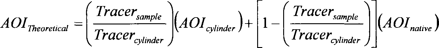
Where:
AOITheoretical = Theoretical analyte of interest concentration (ppm).
Tracersample = Tracer concentration (ppm) as seen by the Fourier Transform Infrared Spectrometer during spiking.
Tracercylinder = The concentration (ppm) of tracer recorded during direct injection of the cylinder to the Fourier Transform Infrared Spectrometer cell.
AOIcylinder = The supplier-certified concentration (ppm) of the analyte of interest gas standard.
AOInative = The native AOI concentration (ppm) of the effluent during stable conditions.
(14) Post-test calibration. At the end of a sampling run and at the end of the field study, record the spectrum of the calibration transfer standard gas. The resulting “final field calibration transfer standard spectrum” must be compared to the initial field calibration transfer standard spectrum to verify suitable stability of the spectroscopic system throughout the course of the field study.
(15) Amendment of analytical routines. The presence of unanticipated interferant compounds and/or the observation of compounds at concentrations outside their expected concentration ranges may necessitate the repetition of portions of the procedures in paragraphs (b)(2) through (b)(14) of this appendix. Such amendments are allowable before final analysis of the data, but must be represented in the documentation required in paragraph (b)(16) of this appendix.
(16) Documentation. The sampling and spiking techniques used to generate the field study spectra and to convert sample spectral information to concentrations must be documented at a level of detail that allows an independent analyst to reproduce the results from the documentation and the stored interferometric data.
(17) Method application. When the required laboratory and field studies have been completed and if the results indicate a suitable degree of accuracy, the methods developed may be applied to practical field measurement tasks. Start Printed Page 63601During field applications, the procedures demonstrated in the field study specified in paragraphs (b)(8) through (b)(16) of this appendix must be adhered to as closely as possible, with the following exceptions specified in paragraphs (b)(17)(i) through (b)(17)(iii) of this appendix:
(i) The sampling lines employed should be as short as practically possible and not longer than those used in the field study.
(ii) Analyte spiking and reactivity checks are required after the installation of or major repair to the sampling system or major change in sample matrix. In these cases, perform three spiked/unspiked samples with calibration transfer standard or a surrogate analyte on a daily basis if time permits and gas standards are easy to obtain and get on-site.
(iii) Sampling and other operational data must be recorded and documented as during the field study, but only the interferometric data needed to reproduce actual test and spiking data must be stored permanently. The format of this data does not need to be interferograms but may be absorbance spectra or single beams.
(c) When using the flow and dilution measurement protocol specified in section 2.2.6 of EPA 430-R-10-003 (incorporated by reference, see § 98.7), you may determine point-of-use abatement device total volume flow with the modifications specified in paragraphs (c)(1) through (c)(3) of this appendix.
(1) You may introduce the non-reactive, non-native gas used for determining total volume flow and dilution across the point-of-use abatement device at a location between the thermal oxidizer of the point-of-use abatement device and the scrubber.
(2) You may select a location for downstream non-reactive, non-native gas analysis that complies with the requirements in this paragraph (c)(2) of this appendix. The sampling location should be traversed with the sampling probe measuring the non-reactive, non-native gas concentrations to ensure homogeneity of the non-reactive gas and point-of-use abatement device effluent (i.e., stratification test). To test for stratification, measure the non-reactive, non-native gas concentrations at three points on a line passing through the centroidal area. Space the three points at 16.7, 50.0, and 83.3 percent of the measurement line. Sample for a minimum of twice the system response time, determined according to paragraph (c)(3) of this appendix, at each traverse point. Calculate the individual point and mean non-reactive, non-native gas concentrations. If the non-reactive, non-native gas concentration at each traverse point differs from the mean concentration for all traverse points by no more than ±5.0 percent of the mean concentration, the gas stream is considered unstratified and you may collect samples from a single point that most closely matches the mean. If the 5.0 percent criterion is not met, but the concentration at each traverse point differs from the mean concentration for all traverse points by no more than ±10.0 percent of the mean, you may take samples from two points and use the average of the two measurements. Space the two points at 16.7, 50.0, or 83.3 percent of the measurement line. If the concentration at each traverse point differs from the mean concentration for all traverse points by more than ±10.0 percent of the mean but less than 20.0 percent, take samples from three points at 16.7, 50.0, or 83.3 percent of the measurement line and use the average of the three measurements. If the gas stream is found to be stratified because the 20.0 percent criterion for a 3-point test is not met, locate and sample the non-reactive, non-native gas from traverse points for the test in accordance with Sections 11.2 and 11.3 of EPA Method 1 in 40 CFR part 60, appendix A-1. A minimum of 40 non-reactive gas concentration measurements will be collected at three to five different injected non-reactive gas flow rates for determination of point-of-use abatement device effluent flow. The total volume flow of the point-of-use abatement device exhaust will be calculated consistent with the EPA 430-R-10-003 (incorporated by reference, see § 98.7) Equations 1 through 7.
(3) You must determine the measurement system response time according to paragraphs (c)(3)(i) through (c)(3)(iii) of this appendix.
(i) Before sampling begins, introduce ambient air at the probe upstream of all sample condition components in system calibration mode. Record the time it takes for the measured concentration of a selected compound (for example, carbon dioxide) to reach steady state.
(ii) Introduce nitrogen in the system calibration mode and record the time required for the concentration of the selected compound to reach steady state.
(iii) Observe the time required to achieve 95 percent of a stable response for both nitrogen and ambient air. The longer interval is the measurement system response time.
Footnotes
1. 2006 IPCC Guidelines for National Greenhouse Gas Inventories, Prepared by the National Greenhouse Gas Inventories Programme, Eggleston H.S., Buendia L., Miwa K., Ngara T. and Tanabe K. (eds). Hayama, Kanagawa, Japan.
Back to Citation2. The EPA performed an uncertainty analysis that found that, depending on the wafer size and gas usage patterns of the fab, the default emission factor approach would result in estimates with uncertainties between approximately 10 and 40 percent; see “Technical Support for Modifications to the Fluorinated Greenhouse Gas Emission Estimation Method Option for Semiconductor Facilities under Subpart I,” Docket ID No. EPA-HQ-OAR-2011-0028.
Back to Citation3. 2006 IPCC Guidelines for National Greenhouse Gas Inventories, Prepared by the National Greenhouse Gas Inventories Programme, Eggleston H.S., Buendia L., Miwa K., Ngara T. and Tanabe K. (eds). Hayama, Kanagawa, Japan. Available at: http://www.ipcc-nggip.iges.or.jp/public/2006gl/index.html
Back to Citation4. Facilities manufacturing MEMS, PVs, and LCDs use the same method regardless of facility manufacturing capacity. Facility manufacturing capacity is still used to determine applicability according to 40 CFR 98.91.
Back to Citation5. Available at: http://www.epa.gov/semiconductor-pfc/documents/dre_protocol.pdf (March 2010).
Back to Citation6. Benaway, B., Hall, S., Laush, C., Ridgeway, R., Sherer, M., & Trammell, S. (2009). “Guideline for Environmental Characterization of Semiconductor Process Equipment—Revision 2”, TT#06124825B-ENG, International SEMATECH Manufacturing Initiative (ISMI), December 2009. Available at: http://www.sematech.org/docubase/document/4825beng.pdf.
Back to Citation7. Laush, C., Sherer, M., & Worth, W. (2006). “Guideline for Environmental Characterization of Semiconductor Process Equipment”, TT#06124825A-ENG, International SEMATECH Manufacturing Initiative (ISMI), December 2006. Available at: https://supplier.intel.com/static/EHS/4825aeng.pdf.
Back to Citation8. “Significantly different” could be defined as using a markedly different gas mixture than the mixture used by previous processes applied to achieve the same end (i.e., etch the same film or feature), similar to the criteria used to determine when new stack testing is warranted. Other possible criteria include radio frequency (RF) power and flow rate.
Back to Citation9. These reporting elements include data elements that have been designated as “inputs to emissions equations” in the August 25, 2011 final rule titled, “Change to the Reporting Date for Certain Data Elements Required Under the Mandatory Reporting of Greenhouse Gases Rule” (76 FR 53057), and listed in Table A-7 of subpart A. Consistent with the proposed amendments to subpart I, we are proposing to remove these subpart I inputs to emissions equations data elements from table A-7 so that they would not be required to be reported by March 31, 2015. More information on this proposed change can be found at the end of Section III.C of this preamble.
Back to Citation10. The 2011 Final CBI Rule created 11 direct emitter data categories, including the 10 data categories listed in Table 5 of this preamble and an inputs to emissions equations data category. However, EPA has not made final confidentiality determinations for any data element assigned to the inputs to emissions equations data category either in the 2011 Final CBI Rule or any other rulemaking.
Back to Citation[FR Doc. 2012-22348 Filed 10-15-12; 8:45 am]
BILLING CODE 6560-50-P


Document Information
- Comments Received:
- 0 Comments
- Published:
- 10/16/2012
- Department:
- Environmental Protection Agency
- Entry Type:
- Proposed Rule
- Action:
- Proposed rule; Grant of Reconsideration.
- Document Number:
- 2012-22348
- Dates:
- Comments. Comments must be received on or before December 17, 2012.
- Pages:
- 63537-63601 (65 pages)
- Docket Numbers:
- EPA-HQ-OAR-2011-0028, FRL-9726-7
- RINs:
- 2060-AR61: GHG Reporting--Change to Calculation Methodologies for Subpart I
- RIN Links:
- https://www.federalregister.gov/regulations/2060-AR61/ghg-reporting-change-to-calculation-methodologies-for-subpart-i
- Topics:
- Administrative practice and procedure, Environmental protection, Greenhouse gases, Reporting and recordkeeping requirements
- PDF File:
- 2012-22348.pdf
- Supporting Documents:
- » Memorandum to Docket from Alexis McKittrick, USEPA/Climate Change on September 18, 2013
- » ICR Worksheet Change: Greenhouse Gas Reporting Program: Final Amendments and Confidentiality Determinations for Subpart I
- » Final Technical Documentation - Revision of Default Utilization Rates and By-Product Formation Rates; Revision of Default Destruction and Removal Efficiencies for Semiconductor Facilities under Subpart I; and Revision of Maximum Field Detection Limits for
- » Reporting of Greenhouse Gases – Revisions to the Electronics Manufacturing Category of the Greenhouse Gas Reporting Rule: EPA'a Responses to Public Comments
- » Greenhouse Gas Reporting Program: Final Amendments and Confidentiality Determinations for Subpart I; Notice of Final Action on Reconsideration
- » EPA-SIA Meeting June 10, 2013
- » USEPA/SIA Meeting - May 8, 2013
- » USEPA / SIA Meeting March 12, 2013
- » January 3, 2013 EPA and Samsung phone call notes regarding Samsung Testing Results
- » Phone call between EPA and SIA on October 24, 2012
- CFR: (8)
- 40 CFR 98.7
- 40 CFR 98.91
- 40 CFR 98.92
- 40 CFR 98.93
- 40 CFR 98.94
- More ...