-
Start Preamble
Start Printed Page 63922
AGENCY:
Federal Aviation Administration (FAA), DOT.
ACTION:
Notice of proposed rulemaking (NPRM).
SUMMARY:
The Associate Administrator for Commercial Space Transportation of the Federal Aviation Administration (FAA), Department of Transportation (DOT), is proposing to amend the FAA's commercial space transportation regulations. The FAA proposes to amend its regulations to codify its license application process for launch from a non-federal launch site. A non-federal launch site is a launch site not located on a federal launch range. The proposed regulations are also intended to codify the safety requirements for launch operators regarding license requirements, criteria, and responsibilities in order to protect the public from the hazards of launch for launch from a federal launch range or a non-federal launch site.
DATES:
Send your comments on or before February 22, 2001.
ADDRESSES:
Address your comments to the Docket Management System, U.S. Department of Transportation, Room Plaza 401, 400 Seventh Street, SW., Washington, DC 20590-0001. You must identify the docket number FAA-2000-7953 at the beginning of your comments, and you should submit two copies of your comments. If you wish to receive confirmation that FAA received your comments, include a self-addressed, stamped postcard. You may submit and review comments through the Internet at http://dms.dot.gov. You may review the public docket containing comments to these proposed regulations in person in the Dockets Office between 9:00 a.m. and 5:00 p.m., Monday through Friday, except Federal holidays. The Dockets Office is on the plaza level of the NASSIF Building at the Department of Transportation at the above address.
Start Further InfoFOR FURTHER INFORMATION CONTACT:
Michael Dook, Licensing and Safety Division (AST-200), Associate Administrator for Commercial Space Transportation, Federal Aviation Administration, DOT, Room 331, 800 Independence Avenue, SW., Washington, DC 20591; telephone (202) 267-8462; or Laura Montgomery, Office of the Chief Counsel (AGC-200), Federal Aviation Administration, DOT, Room 915, 800 Independence Avenue, SW., Washington, DC 20591; telephone (202) 267-3150.
End Further Info End Preamble Start Supplemental InformationSUPPLEMENTARY INFORMATION:
Comments Invited
Interested persons are invited to participate in the making of the proposed action by submitting such written data, views, or arguments as they may desire. Comments relating to the environmental, energy, federalism, or economic impact that might result from adopting the proposals in this document also are invited. Substantive comments should be accompanied by cost estimates. Comments must identify the regulatory docket or notice number and be submitted in duplicate to the DOT Rules Docket address specified above.
All comments received, as well as a report summarizing each substantive public contact with FAA personnel concerning this proposed rulemaking, will be filed in the docket. The docket is available for public inspection before and after the comment closing date.
The Administrator will consider all comments received on or before the closing date before taking action on this proposed rulemaking. Late-filed comments will be considered to the extent practicable, and consistent with statutory deadlines. The proposals in this document may be changed in light of the comments received.
Commenters wishing the FAA to acknowledge receipt of their comments submitted in response to this document must include a pre-addressed, stamped postcard with those comments on which the following statement is made: “Comments to Docket No. FAA-2000-7953.” The postcard will be date stamped and mailed to the commenter.
Availability of Rulemaking Documents
You can get an electronic copy using the Internet by taking the following steps:
(1) Go to the search function of the Department of Transportation's electronic Docket Management System (DMS) Web page (http://dms.dot.gov/search).
(2) On the search page type in the last four digits of the Docket number shown at the beginning of this notice. Click on “search.”
(3) On the next page, which contains the Docket summary information for the Docket you selected, click on the document number of the item you wish to view.
You can also get an electronic copy using the Internet through FAA's web page at http://www.faa.gov/avr/arm/nprm/nprm.htm or the Federal Register's web page at http://www.access.gpo.gov/su_docs/aces/aces140.html.
You can also get a copy by submitting a request to the Federal Aviation Administration, Office of Rulemaking, ARM-1, 800 Independence Avenue SW., Washington, DC 20591, or by calling (202) 267-9680. Make sure to identify the docket number, notice number, or amendment number of this rulemaking.
I. Introduction
By this notice of proposed rulemaking, the FAA proposes licensing and safety requirements for the conduct of a launch. The proposed requirements for obtaining a license would apply to a launch operator planning to launch from a non-federal launch site. A non-federal launch site is a launch site that is not located at a federal launch range. The proposed regulations for obtaining a license would not, however, apply to any launch from a non-federal launch site where a federal launch range performs the safety functions. For such a launch, the licensing requirements of 14 CFR part 415, subpart C applies. The proposed regulations are also intended to codify the safety requirements that a launch operator must satisfy to protect the public from the hazards of launch. The safety requirements contained in this proposed regulation apply to all licensed launches of expendable launch vehicles whether from a federal launch range or a non-federal launch site. This notice provides information regarding the criteria for obtaining a launch license, the responsibilities with which a launch licensee must comply, and operational requirements.
II. Background
The Commercial Space Launch Act of 1984, as codified and amended at 49 U.S.C. Subtitle IX—Commercial Space Transportation, ch. 701, Commercial Space Launch Activities, 49 U.S.C. 70101-70121 (the Act), authorizes the Department of Transportation and thus the FAA, through delegations,[1] to oversee, license and regulate commercial launch and reentry activities and the operation of launch and reentry sites as carried out by U.S. citizens or within the United States. 49 U.S.C. 70104, 70105. The Act directs the FAA to exercise this responsibility consistent with public health and safety, Start Printed Page 63923safety of property, and the national security and foreign policy interests of the United States. 49 U.S.C. 70105. The FAA is also responsible for encouraging, facilitating and promoting commercial space launches by the private sector. 49 U.S.C. 70103. A 1996 National Space Policy recognizes the Department of Transportation as the lead federal agency for regulatory guidance regarding commercial space transportation activities.
The FAA licenses commercial launches, the subject of this notice of proposed rulemaking in accordance with the Act and 14 CFR Ch. III. Until recently, all commercial launches took place under the cognizance of federal launch range safety organizations, which impose comprehensive safety requirements on launch operators. The FAA has been able to rely significantly on the safety oversight activities of the federal launch ranges. Consequently, many safety issues did not need to be addressed explicitly in the FAA's regulations. That has now changed.
The commercial space transportation industry continues to grow and diversify. Between the first licensed commercial launch in March 1989 and July 2000, 130 licensed launches have taken place from five different launch sites, including launches from a non-federal launch site, and from launch sites operated by licensed launch site operators. The vehicles have included traditional orbital expendable launch vehicles, such as the Atlas, Titan, and Delta, and sub-orbital Black Brant boosters, new expendable launch vehicles using traditional launch techniques, such as Athena and Conestoga, and unique vehicles, such as the air-borne Pegasus. The commercial launch industry has evolved from one relying on traditional orbital and sub-orbital launch vehicles to one with a diverse mix of vehicles using new technology and new concepts. A number of international ventures involving U.S. companies have also formed, further adding to this diversity.
Developments in cost savings and innovation are not confined to the launch industry. The launch site industry has also made progress. Commercial launch site operators are coming on line with the goal of providing flexible and cost-effective facilities both for existing launch vehicles and for new vehicles. When the commercial launch industry began, commercial launch companies based their launch operations at federal launch ranges operated by the Department of Defense (DOD) and the National Aeronautics and Space Administration (NASA). The Eastern Range, where the 45th Space Wing provides launch safety services, located at Cape Canaveral Air Station in Florida (CCAS), and the Western Range, where the 30th Space Wing provides launch safety services, located at Vandenberg Air Force Base (VAFB), in California are Federal launch ranges that support licensed launches. Both are operated by the U.S. Air Force. Wallops Flight Facility in Virginia, operated by NASA; White Sands Missile Range (WSMR) in New Mexico and Kwajalein Missile Range, both operated by the U.S. Army; and the Kauai Test Facility in Hawaii, operated by the U.S. Navy are other federal launch ranges that support licensed launches. Federal launch ranges provide the advantage of existing launch infrastructure and range safety services. Launch companies are able to obtain a number of services from a federal launch range, including radar, tracking and telemetry, flight termination and other launch services.
Today, most commercial launches still take place from federal launch ranges. However, the FAA anticipates that this pattern will change, as non-federal launch sites become more prevalent. On September 19, 1996, the FAA granted the first license to operate a launch site to Spaceport Systems International (SSI) to operate California Spaceport. That launch site is located within VAFB. Three other launch site operators have received licenses. The Spaceport Florida Authority (SFA) received an FAA license to operate Launch Complex 46 at CCAS as a launch site. Virginia Commercial Space Flight Authority (VCSFA) received a license to operate Virginia Spaceflight Center (VSC) within NASA's Wallops Flight Facility. Most recently, Alaska Aerospace Development Corporation (AADC) received a license to operate Kodiak Launch Complex (KLC) on Kodiak Island, Alaska as a launch site.
Whether launching from a federal launch range, a launch site located on a federal range, or a non-federal launch site, a launch operator is responsible for ground and flight safety under its FAA license. At a federal launch range a launch operator must comply with the rules and procedures of the federal range. The safety rules, procedures and practices, in concert with the safety functions of the federal launch ranges, have been assessed by the FAA, and found to satisfy the majority of the FAA's safety concerns. In contrast, when launching from a non-federal launch site, a launch operator's responsibility for ground and flight safety takes on added importance. In the absence of federal launch range oversight, it will be incumbent upon each launch operator to demonstrate the adequacy of its ground and flight safety to the FAA.
An NPRM containing licensing and safety requirements for the operation of a launch site was issued in June 1999, and that notice makes clear that a licensed launch site operator will not be playing the same role as a federal launch range. Licensing and Safety Requirements for Operation of a Launch Site, Notice of Proposed Rulemaking, 64 FR 34315 (Jun. 25, 1999) (“Launch Site NPRM”). That notice proposes specific requirements for operating a launch site, including the operation of a non-federal launch site; however, the notice proposes more limited launch site operator licensee requirements with respect to flight safety of a launch from a non-federal site. A launch site operator is not required to perform in a similar capacity as the current federal launch ranges. The FAA holds a launch licensee, not a launch site operator, responsible for flight safety, even in those cases where a launch site operator provides services in support of a launch. In that context, a launch site operator acts as a contractor or subcontractor to a licensed launch operator. The majority of public safety requirements for launch related ground and flight operations fall upon the launch licensee.
In addition to licensing the operation of the first non-federal launch site, the FAA issued, as of March 1999, its first launch license for launch from a non-federal launch site, which was, in this case, the Pacific Ocean. For this launch, no federal launch range safety review was available. Sea Launch Limited Partnership (Sea Launch), the licensee, was successful in conducting its first launch of a commercial rocket from a modified mobile oil rig located in the Pacific Ocean. Because Sea Launch does not plan to offer its launch platform or location to others for launch, the FAA did not require it to obtain a license to operate a launch site; accordingly, it needed only obtain a launch license. The FAA's approach to Sea Launch's license application was to ensure an equivalent level of safety as has been sought at the federal launch ranges. Although the foreign safety system, technology, procedures, and operations create a number of differences, the FAA was able to use the federal launch range approach as a benchmark to achieving safety for the FAA's safety determination.
The current regulations, 14 CFR part 415, governing launch primarily address launches as they take place from Department of Defense or National Aeronautics and Space Administration (NASA) launch ranges, and treat Start Printed Page 63924launches from a non-federal launch site on a case by case basis. The licensing regulations for launch from a federal launch range are designed to avoid duplication of effort between the FAA and the federal launch ranges in overseeing the safety of launches at the federal ranges. Although the FAA does require information and analyses not required by federal ranges to ensure that all flight safety issues are addressed, and imposes certain additional requirements derived from recommendations arising from a National Transportation Safety Board investigation, the FAA does not duplicate the safety assessments performed by federal launch ranges. The ranges require compliance with their safety rules as a condition of using their facilities and services. The federal ranges act, in effect, both as landlords and as providers of launch facilities and services. Under this notice of proposed rulemaking, that licensing approach will continue. A launch operator license applicant proposing to launch from a federal launch range will continue to be governed by subpart C of part 415. A launch operator proposing to launch from a non-federal launch site would be subject to the requirements proposed by subpart F which are, because of the lack of federal launch range involvement, more detailed in order to permit the FAA to adequately review the safety of each proposed launch.
A federal launch range requires a launch operator to provide data regarding its proposed launch. The range evaluates the data to ascertain whether the launch operator will comply with range requirements. The range also uses the data to prepare range support for the mission. DOD ranges require that a launch operator apply for and obtain specific mandatory approvals from the range in order to conduct certain specified operations. For example, the Air Force's “Eastern and Western Range Requirements 127-1,” (Mar. 1995) [2] (“EWR 127-1”) require a launch operator to obtain approvals for hazardous and safety critical procedures before the range will allow those operations to proceed. In the event that a launch operator's proposal does not fully comply with range requirements, a range may issue a deviation or a waiver if the mission objectives of the launch operator could not otherwise be achieved. A range may issue a deviation to allow a launch even when a launch operator's designs or proposed operations do not comply with range requirements. A range may issue a waiver when it is discovered after production that hardware does not satisfy range requirements or when it is discovered that operations do not meet range requirements after operations have begun at a federal range. A range will allow a deviation or grant a waiver only under unique and compelling circumstances.
The FAA performed baseline assessments of various federal launch ranges and found their safety services adequate. Under FAA regulations, the FAA does not require an applicant to demonstrate the adequacy of the range services it proposes to employ if the applicable baseline assessment included those federal launch range services and if those services remain adequate. Certain showings regarding the applicant's own capabilities are still required. The FAA requires specific information regarding the interface between the safety organizations of a federal launch range and of an applicant. In the event that a service or procedure upon which an applicant proposes to rely is not within the documented experience of the federal launch range that the applicant proposes to utilize, the applicant would have to demonstrate the safety of that particular aspect of its launch. This is also true if a documented range safety service has changed significantly or has experienced a recent failure. In those cases, the burden of demonstrating safety shifts to the applicant.
III. Discussion of Proposed Licensing and Safety Regulations for Launch
A. Proposed Revisions to Parts 415 and 417
The approach the FAA followed in developing technical requirements for this proposed rule is to build on the safety success of federal launch ranges and to seek the same high level of safety that the federal ranges have achieved. Wherever appropriate for public safety, federal launch range practices were used as the basis for the development of the FAA's regulatory regime. Additionally, this proposed rule would allow for flexibility through the use of performance standards where appropriate, and identifies specific technical requirements where necessary to ensure safety. The FAA worked extensively with federal launch range safety personnel to refine and adapt many of the federal range requirements to a performance standard approach for incorporation into this proposed rule. The text responds to the complexity of space launch systems and the potential for negative consequences to public safety. The proposed regulations specify detailed processes, procedures, analyses, and general safety system design requirements. Where necessary, for critical safety hardware and software, this proposed rule provides design and detailed test requirements. In every case, the proposed regulations define the material that must be prepared and submitted as part of a license application or by a licensee before launch. The FAA also proposes to build flexibility into its requirements. Although the proposed regulations would provide the requirements with which a licensee must comply, the FAA anticipates that a launch operator might wish to employ alternative means of achieving the same safety goal. In that case, if a launch operator can clearly and convincingly demonstrate an equivalent level of safety, the FAA would consider accepting that alternative, and describing it for the benefit of others through the notice, the FAA's advisory circular process or some other method.
This notice of proposed rulemaking proposes safety requirements for licensed launch, whether from a non-federal launch site or a federal launch range. It is the FAA's understanding that the U.S. Air Force launch ranges intend eventually to cross-reference the same requirements for flight for government launches. In the course of creating the requirements for this proposed rule, the FAA consulted with the federal launch ranges. As a result of these consultations, what the FAA understands to be a general sentiment within the launch community in favor of consistent requirements, and the recommendations contained in the White House's report, The Future of the Space Launch Bases and Ranges, (2000) the FAA and the Air Force plan to establish common safety standards for the flight of a launch vehicle. The FAA will implement its requirements through rulemaking, and launch operators using Air Force ranges for commercial launch would have to abide by the FAA regulations for flight safety in proposed part 417. Because the Air Force's ground safety requirements still provide greater specificity than what the FAA proposes through this notice, the Air Force does not, at this time, plan to substitute the FAA's proposed ground safety requirements for its own, but, because a launch operator will have to comply with the requirements of part 417, that launch operator will have to ensure that it complies with the FAA's proposed ground safety requirements as well. The FAA anticipates that, in most instances, satisfaction of the Air Force Start Printed Page 63925requirements will satisfy the FAA's ground safety requirements. In the event of conflicts, the FAA's requirements will govern licensed launch operators.
Both the Air Force and the FAA anticipate tangible benefits to having common safety standards. Because the FAA is building upon the requirements of the federal launch ranges, this proposed rule is meant to preserve the best of the Air Force public safety experience and expertise. The Air Force, which has subjected its own requirements to the scrutiny and comments of its range users in the past, will be able to rely on the fact that the FAA's proposed requirements will undergo the public notice and comment period mandated by the Administrative Procedure Act. This proposed rule will provide a forum for public participation on the proposed standards and economic impacts. An FAA rulemaking requires a cost benefit analysis, which is also subject to public comment, and ensures that issues regarding cost are taken into account. The FAA, in turn, is able to leverage the technical expertise of the Air Force legacy in promulgating its requirements. The FAA and the Air Force foresee greater ease of administration for launch operators and the government, as well as greater uniformity of treatment, with a common set of national standards.
This notice proposes to establish requirements for a flight safety analysis that covers the hazards of normal and non-normal flight. The results of the analysis will be used to develop and implement flight safety rules and procedures that govern the licensed launch. The flight safety analysis is a critical tool for determining that public safety is being adequately addressed. The analysis must accurately reflect the true circumstances of each launch. Consequently, the proposed rules would specify performance standards for each critical part of a flight safety analysis as well as identifying the specific safety criteria that must be met.
This notice would cover a number of major flight safety analysis issues. Flight control lines are necessary for a flight safety analysis. Establishing flight control lines involves the identification of those areas that must be protected from potential adverse effects of a launch vehicle's flight. Flight control lines are material input to the flight safety analysis and the determination of flight safety limits. They depend on the location of population centers, foreign territorial boundaries, and other areas that must be protected. Flight safety limits are used during a launch to determine when a malfunctioning vehicle's flight must be terminated to ensure that any adverse effects are contained. Flight safety limits may be a function of time and depend on the vehicle's debris footprint.
This notice of proposed rulemaking addresses other flight safety measures. For example, wind weighting is a technique used to determine launch azimuth and elevation settings for unguided launch vehicles, which are typically sub-orbital sounding rockets. Wind weighting predicts the wind effects on impact point displacement during the thrusting phases of flight as well as the ballistic free-fall phase of each launch vehicle stage.
Hazard areas must be established for both preflight processing of a launch vehicle and flight. Hazard areas are established to provide protection from both normal and anomalous launch events. The presence of the public in a hazard area is a constraint on preflight processing and flight, and must be controlled, typically by controlling access to the area or through flight commit criteria that depend on real-time surveys of the area at the time of flight. This notice proposes to specify the analysis that a license applicant must perform to define the appropriate hazard areas for each launch. These hazard areas generally include a launch hazard area that accounts for people, aircraft, and any ships, impact hazard areas for planned debris resulting from normal flight, and hazard areas for unique hazards such as toxic or radiological materials.
An applicant must demonstrate satisfaction of the FAA's risk criteria. This may be accomplished if a launch operator is able to show that the risk of casualties to the general public is acceptably low. An applicant must show that the collective casualty expectancy (EC) risk of the proposed launch is equal to or less than the FAA's established criteria of 30×10−6. This is a critical measure used to evaluate potential public risk due to a proposed launch. An applicant must also show that its proposed launch will be conducted without exceeding an individual casualty probability (PC) of 1×10⁻⁶. Not all federal launch ranges require an individual risk analysis. In most cases, if 30×10−6 is met, individual risk is also less than 1×10⁻⁶. This is not, however, always the case. The need to evaluate individual risk varies depending on the specifics of the launch and the launch site. Because FAA regulations must address the broad range of non-federal launch sites and launch vehicle combinations, the FAA proposes to require a launch operator to demonstrate that the individual risk criteria will not be exceeded for each launch regardless of whether the launch occurs from a non-federal launch site or a federal launch range. This notice will provide a method for accomplishing these analyses and allow for variations and possible simplifications to the analysis based on the applicant's specific situation. The applicant would perform risk analysis to demonstrate that each proposed launch will not exceed established criteria for the impact probability of hitting aircraft and ships.
The other essential component for flight safety is a flight safety system. The primary purpose of a flight safety system is to monitor a launch vehicle's flight status and provide the positive control needed to prevent the launch vehicle from impacting populated or other protected areas in the event of a vehicle failure. The requirements for properly qualifying the proposed flight safety system and validating its performance are critical. Comprehensive flight safety system requirements will be provided that are designed to ensure that a launch operator implements a highly reliable, acceptable system.
This proposed rulemaking addresses important components of and major issues related to a flight safety system. A typical flight safety system is composed of a flight termination system and a command control system. This notice proposes to define a flight termination system (FTS) as consisting of all components that are on board a launch vehicle and are needed to control the termination of a launch vehicle's flight. An FTS may also include automatic destruct system components designed to activate upon vehicle breakup or premature separation of individual powered stages or strap-on motors. This notice proposes requirements for the FTS components onboard a launch vehicle as well as command control components that are typically ground based, including associated software. A highly reliable FTS is critical to ensuring public safety. This notice would define a process for obtaining the necessary reliability. That process would consist of specific FTS design standards and criteria, a reliability analysis of the FTS design, and comprehensive testing to qualify the FTS design and certify and accept FTS components.
The proposed requirements would also address other elements of the flight safety system. This notice of proposed rulemaking would include requirements for compatible vehicle tracking, visual data sources, telemetry, communications, display, and recording systems that are necessary as part of the flight safety system to support a flight Start Printed Page 63926termination decision. The licensee would be responsible for ensuring that these required systems are available to support the launch. A flight safety system must be complemented with, and operated by a qualified flight safety crew that includes a flight safety official and support personnel. This proposed rule would identify the flight safety crew positions and the personnel qualifications required for each position. The FAA's proposed training and qualification approach is an adaptation of federal launch range practices.
This notice also addresses ground safety issues related to the preparation of a launch vehicle for flight. Many issues related to the safety of ground operations at a launch site are subject to regulation by other federal agencies. This notice would address ground safety issues, not otherwise addressed by other federal regulations, that are unique to space launch processing and that could affect the general public. A launch operator licensee would be responsible for developing and implementing a ground safety program in compliance with the specified standards, and should note that this proposed rulemaking does not supersede the ground safety requirements of other regulatory agencies.
Ground safety issues may be addressed through a number of measures in this notice. This proposed rulemaking includes a hazard assessment to ensure the safety of ground operations. A launch operator would be required to perform a hazard analysis for all hazardous operations to identify the potential of each hazard for affecting public safety. This proposed rulemaking would define requirements, processes, and procedures for mitigating identified public safety hazards. Launch processing typically involves the use of toxic and hazardous materials. This proposed rule would define ground safety program requirements designed to protect the public from these substances. The use of non-ionizing radiation in the form of communications and radar systems is also typical of launch processing. Proper control of such sources of energy is of particular concern due to the many explosives that could be inadvertently initiated and that are often present at a launch site. This proposed rulemaking would define ground safety program requirements designed to protect the public from non-ionizing radiation. A launch vehicle or payload may include materials that give off ionizing radiation. The presence of ionizing radiation is a safety issue that must be reviewed for each launch and requires that proper procedures be followed. There are many ground safety issues involving explosives associated with launch processing. The NPRM on licensing and safety requirements for the operation of a launch site addresses locating explosive substances at a launch site, and identifies appropriate safety separation distances, based on quantity, between facilities at the site and the public. In most cases, maintaining proper separation distances will provide protection for the general public. This proposed rulemaking would define ground safety program requirements for protecting the public from explosives through the maintenance of proper separation distances during operations and preventive explosive safety processes and procedures, including prevention of inadvertent initiation of explosives and propellants.
B. Payload Review and Determination
The proposed requirements address hazards that a payload may create during launch. This proposed rulemaking continues the agency's practice of addressing hazards presented by payloads during the flight of a launch vehicle. This includes payloads otherwise exempt from a payload review. The FAA wishes to clarify that flight safety analysis includes even those payloads exempted by 14 CFR 415.53, and is proposing to amend the text of § 415.51 to clarify accordingly. As is evident from inspection of the neighboring provisions, sections 415.51 (“the FAA reviews a payload proposed for launch to determine whether its launch would jeopardize public health and safety”) and 415.53 (“each payload is subject to compliance monitoring to determine whether its launch would jeopardize public health and safety”), the FAA intended to include safety issues within a payload review. Nonetheless, in order to avoid confusion, the FAA proposes to amend § 415.51 to state that all payloads, exempt or not, are subject to the safety requirements of subparts C and F of this part and of part 417. This should make clear that the exemption of Federal Communications Commission (FCC) or National Oceanic & Atmospheric Administration (NOAA) regulated payloads or those owned or operated by the U.S. Government applies to the payload determination and not to the safety reviews or requirements.
The Act provides the FAA authority over payloads. See 49 U.S.C. 70104; Commercial Space Transportation; Licensing Regulations, Interim Final Rule, 51 FR 6870, 6871 (Feb. 26, 1986) (“The Act gives the [agency] authority to determine whether the launch of a payload is inimical to the national interests specified in the Act and does not exclude any relevant factor from the [agency's] consideration.”) The commercial space transportation regulations implemented this authority, first, through a mission review, see 14 CFR 415.21-415.25 (1988), and then through the payload review adopted in 1999, see 14 CFR 415.51-415.63 (1999).
The Act also contains provisions describing the authority of various agencies with regard to certain payloads. The Act does not affect the authority of the FCC or the Secretary of Commerce under the Land Remote-Sensing Commercialization Act of 1984. 49 U.S.C. 70117(b). This means that these agencies may continue in their regulation of communications satellites and land remote sensing satellites. Accordingly, the FAA does not conduct a payload review of payloads that are subject to regulation by the Federal Communications Commission or the Department of Commerce, National Oceanic and Atmospheric Administration, or that are owned or operated by the U.S. government. This means that the FAA does not review those payloads for their impact on the national interests identified in the Act.
The FAA does, however, possess and exercise safety authority over issues presented by payload hazards during flight of a launch vehicle. The FAA recognizes that the legislative history accompanying the requirement in 49 U.S.C. 70104(b) that a licensee may launch a payload only if the payload complies with the requirements of the laws of the United States related to launching a payload, indicates that Congress did not want communications or land remote sensing satellites subjected to a duplicative regulatory process. See Commercial Space Launches, Sen. Committee Rep. No. 656, 98th Cong., 2d Sess., 15 (1984). The Committee recognized, for example, that the FCC provided authorization for the launch of a communications satellite and would therefore require no separate “documentation or certification” by the FAA. Id. Nor did Congress intend that the FAA obtain the authority “to override or modify any decision by the FCC to authorize the launch or operations of a communications satellite.” Id. at 16. The FAA does not purport to authorize the operation of communications satellites. That is why the exemption in § 415.53 exists. What the FAA does require, however, is information sufficient to evaluate the safety of a proposed launch. The FCC and NOAA do not analyze the launch safety of communications or land remote sensing satellites. Accordingly, Start Printed Page 63927the FAA's proposed safety requirements would not constitute duplicative regulation.
If the payload hazards dictate a change in commit criteria, trajectory or other safety related decision, the launch operator and the FAA need to be able to assess and respond to the hazards posed by the satellite. A satellite's hazards may consist of fuel, debris or both. In this regard the FAA notes that the Senate Committee, in discussing the agency's authority to issue an emergency order stopping a launch, recognized that the agency could have concerns “that may relate to the launch vehicle or its payload.” Id. at 24. This explicit recognition of the FAA's ability to respond to payload concerns supports the FAA's interpretation of the Act: subsection 70117(b) provides that the authority of the FCC and NOAA remain unaffected by the Act, but means nothing more than that. Although the FAA should not duplicate the roles of the FCC or NOAA, it may address areas not otherwise encompassed by their regulatory schemes, namely, the safety issues surrounding any particular launch. Accordingly, the FAA will continue to address payload safety issues that relate to the transport, or launch, of a payload, regardless of whether the payload is within the jurisdiction of the FCC or NOAA or whether it is owned or operated by the U.S. Government.
C. Safety Review for Launch From a Non-Federal Launch Site
Under current practice, the FAA requires a safety review for launch from a non-federal launch site. By this proposed rulemaking, the FAA proposes to codify its requirements for the safety review. Proposed part 417 contains the safety requirements with which a licensee must comply. Part 415, subpart F, would require a license applicant to demonstrate how it will satisfy the requirements of part 417 in order to obtain a license. The FAA would issue a safety approval if an applicant demonstrated that it would meet the safety responsibilities and requirements for launch. The safety review would require an applicant to submit data, prepare test plans, conduct and supply analyses and do so in accordance with specified timetables.
Not unlike what a launch operator must submit to a federal launch range in order to launch from a site such as Cape Canaveral or Vandenberg Air Force Base, a launch operator must demonstrate that it will satisfy the FAA's regulatory requirements. A launch operator will notice some differences. The same work will be performed, but by different entities. Where, for example, a federal launch range will perform much of the flight safety analysis for a launch operator to launch, the lack of a federal range and the proposed requirements would settle that task upon the launch operator. In the course of its safety review, the FAA will review the launch operator's information for validity and accuracy.
D. Part 417, Launch Safety
This proposed rulemaking clarifies the roles and responsibilities of a launch operator licensee. It specifies that a launch operator is responsible under an FAA license for the safety of the flight of its launch vehicle and the launch processing, or preparation of that launch vehicle for flight, at a U.S. launch site.
A launch license encompasses both the flight of a launch vehicle, referred to in common parlance as “launch,” and the launch processing of that vehicle. One of the idiosyncrasies of the Act is its definition of “launch.” The Act defines launch not only as including the flight of a launch vehicle, but as including activities “involved in the preparation of a launch vehicle or payload for launch, when those activities take place at a launch site in the United States.” 49 U.S.C. 70102(3). Accordingly, a launch license covers flight and launch processing, and a launch operator is responsible for the safety of both.
This proposed rulemaking also clarifies a number of issues of which a launch operator must be cognizant. A launch license does not relieve a licensee of other legal obligations. Under 49 U.S.C. 70105(b), unless otherwise provided by that subsection, all requirements of the laws of the United States applicable to the launch of a launch vehicle are license requirements as well. Additionally, this proposed rulemaking would impose on a launch operator the requirement to coordinate with a launch site operator in order for the launch site operator to satisfy its regulatory obligations.
The proposed requirements also highlight the interplay between the application process and compliance with the obligations of a licensee. Because the FAA grants a license based on the representations contained in a launch operator's license application, part of a licensee's obligations under its license are to ensure the continuing accuracy of all material representations. The FAA proposes to impose affirmative verification measures in order to ensure that a launch operator is operating as it represented it would.
In order to outline the proposed regulations, proposed subpart B of part 417 would serve as a guide to other parts of the regulations. It summarizes what a launch operator needs to address to achieve public safety and refers to the particular subpart, section and appendices that contain detailed requirements. This subpart would address a launch operator's safety organization, safety personnel and codify various criteria for the risks and hazards associated with launch.
E. Flight Safety Analysis
1. Introduction
A launch operator would be required to perform flight safety analysis to demonstrate how it would monitor and control risk to the public from hazards associated with normal launch vehicle flight and the potential hazards associated with the flight of a malfunctioning launch vehicle. The proposed regulations would require that a launch operator's analysis consist of a number of separate analyses, both deterministic and probabilistic in content and intent. For all expendable launch vehicles, a launch operator's flight safety analysis would determine the conditions under which the vehicle could be launched safely by demonstrating that the risk associated with the launch satisfied the public risk criteria. In addition, for a launch vehicle flown with a flight safety system as a means of ensuring public safety, the flight safety analysis would define the conditions that would dictate whether or not the flight of the launch vehicle had to be terminated due to safety considerations.
During the licensing process, the FAA would require a launch operator to submit the products of its analysis to demonstrate that the launch operator performed the required analyses properly and has the ability to conduct a launch safely. After licensing, the FAA would also require a launch operator to submit analysis products for each individual launch to provide the data that the FAA would use to verify a launch operator's compliance with the regulations and the terms of the license for each launch. The proposed analyses would thus demonstrate both capability and specific compliance. This has proved to be a successful process historically. The FAA does not, however, foreclose the possibility that a launch operator could dispense with one or more of the proposed analyses through innovation or the applicability of a previously performed analysis for a past mission to a planned mission. Nonetheless, the FAA would require the products of each of these analyses to verify their validity for those launch Start Printed Page 63928operators employing the more traditional approaches, and to serve as a benchmark against which to measure any alternative approach that a launch operator proposes.
2. Flight Safety Analysis for Launch Vehicles That Use a Flight Safety System to Achieve Public Safety
A launch operator would perform a series of analyses to define the extent of its launch vehicle's capabilities and hazards, both during normal flight and in the event of a malfunction. A launch operator would perform a trajectory analysis to determine a launch vehicle's planned nominal trajectory and the potential three-sigma trajectory dispersions about the nominal trajectory. The three-sigma dispersions, which routinely include the effects of winds on a launch vehicle, about the nominal trajectory define the extent of normal flight. A launch operator would perform a malfunction turn analysis to determine how far a launch vehicle's instantaneous impact point can deviate from the nominal trajectory when a malfunction occurs. A launch operator would perform a debris analysis that identifies inert, explosive, and other hazardous launch vehicle debris, such as toxic debris or debris that produces ionizing radiation, resulting from a launch vehicle malfunction and from any planned jettison of launch vehicle components. A launch vehicle's capabilities and hazards may be significantly affected by winds experienced during flight. A launch operator would perform a wind analysis to determine wind magnitude and direction as a function of altitude for the air space through which the launch vehicle will fly and for the airspace through which any malfunction and jettisoned debris may fall.
The launch operator would perform an analysis to establish flight control lines that define where a launch vehicle would be allowed to fly. As part of this analysis, the launch operator would assess the surroundings of its proposed launch site and trajectory to identify the boundaries of populated and other areas requiring protection from the potential adverse effects of the launch vehicle's flight, including, its possible breakup, whether commanded or accidental. The proposed regulations would require a launch operator to border the identified populated and other areas requiring protection with flight control lines, thus defining the region within which the launch vehicle and any breakup and jettisoned debris must be contained.
The FAA reviewed a recent National Academy of Sciences (the Academy) study that recommended that the federal launch ranges create their impact limit lines, which correlate fairly closely to the FAA's own proposed flight control lines, on the basis of risk. Streamlining Space Launch Range Safety, 22, National Research Council (Apr. 2000) (”Streamlining Safety”). The Academy recommended, among other things, that destruct lines be defined and implemented in a way that is directly traceable to accepted risk standards, including collective (EC) and individual risk. The Academy took exception to the creation of impact limit lines on the basis of risk avoidance. Id. at 20 (citing EWR 127-1, par. 2.3.6: “Whenever possible, the overflight of any inhabited landmasses is discouraged and is approved only if operational requirements make overflight necessary, and risk studies indicate probability of impact and casualty expectancy are acceptable.”) The FAA finds that it cannot pursue this recommendation. In the context of impact limit lines, the report makes no case for basing a decision as to what requires protection on the basis of risk. Instead, it ignores the portion of EWR 127-1 that permits overflight on the basis of risk through the creation of gates, which are the width of a destruct line opened for a normally performing vehicle,. Gates are acceptable only if risk levels are acceptable. EWR 127-1 at par. 2.3.6. The FAA proposes, like the federal launch ranges, to require the protection of populated areas, and permit the creation of gates as an exception to the flight control lines requirement. If the Academy means to suggest that impact limit lines or flight control lines should be created on the basis of risk, the Academy did not suggest how this should be accomplished or provide a justification. The FAA is also troubled by the possibility that the Academy recommendation could mean that certain populated areas and members of the public near a launch site would no longer benefit from being protected from a malfunctioning launch vehicle. The FAA does not believe that the Academy intended to distinguish between the levels of protection some members of the public are afforded. Accordingly, the FAA will not seek to deviate from the federal launch range approach to the creation of either impact limit lines or, as the FAA proposes, flight control lines.
The launch operator would perform a series of analyses to determine the conditions that would require termination of a launch vehicle's flight and to establish flight termination rules. Unless otherwise approved during the licensing process, the proposed regulations would require a launch operator to employ a traditional U.S. flight safety system where flight termination is accomplished by destroying the launch vehicle and ensuring that any resulting hazards are contained within an area that is isolated from the public. In general, if a launch vehicle strays off course, it must be destroyed or its thrust terminated before the vehicle, payload, or resulting debris is able to impact any populated or other protected area outside the established flight control lines.
A launch operator would perform a flight safety limits analysis and institute flight termination rules to establish the conditions under which the launch operator would have to terminate a malfunctioning launch vehicle's flight to ensure that the launch vehicle's debris impact dispersion does not extend beyond the flight control lines, or conflict with the risk criteria. A launch operator's flight safety limits analysis would have to account for any time delay that exists between recognizing that a malfunction has occurred, the point in time that a flight termination command is sent and the launch vehicle's destruction. A launch operator would perform a time delay analysis to determine the elapsed time, including an allowance for the flight safety official's decision and reaction time, between the start of a launch vehicle malfunction or violation of flight safety limits and the final motion of the vehicle's impact point or commanded flight termination.
Additional proposed analyses would address other conditions requiring termination of flight. If a launch vehicle malfunctions and flies a vertical or near vertical trajectory, usually referred to as a straight-up trajectory, rather than following a normal trajectory downrange, a launch operator would perform a straight-up time analysis to determine the latest time-after-liftoff by which flight termination must be initiated. If a launch operator lost all launch vehicle tracking data and did not regain tracking data for an amount of time sufficient for a launch vehicle to reach a populated or other protected area, the launch operator would have to terminate flight. A launch operator would perform a data loss flight time analysis to determine the shortest elapsed thrusting time during which a launch vehicle could move from its normal trajectory to a condition where the public might become endangered.
The FAA would permit flight over any populated or other protected area if a launch operator establishes a gate through a flight control line or other flight safety limit boundary. A launch Start Printed Page 63929operator would perform an analysis to determine any gate in a flight control line or other flight safety limit boundary, through which a launch vehicle would be allowed to pass without a launch operator being required to terminate flight. A launch operator would have to perform a risk analysis to determine whether the overflight permitted by the gate was acceptable and satisfied the risk criteria.
The FAA wishes to caution its licensees that proposed changes in the African gate may affect certain launches, and requests comments from its licensees on the possible impacts. A licensed launch operator would have to satisfy the requirements of proposed part 417. That would include the requirements governing the creation of a gate. The National Academy of Sciences report recommended that the Air Force consider not retaining downrange equipment and facilities in support of the African or other gates. Streamlining Safety at 24. If such a move conflicted with the FAA requirements governing creation and use of a gate, a launch operator would have to provide its own support for any launch employing the gate.
The FAA's proposed requirements would require a launch operator to terminate the flight of an abnormally performing launch vehicle prior to permitting land overflight. The Academy pointed out, without quantifying the costs, that the current downrange equipment that supports a termination decision is expensive. Streamlining Safety at 20. The Academy also noted that coordinating launches with remote facilities complicates range safety operations and increases the risk of delay. Id. The Academy also maintained that the need for downrange facilities was not necessary from a safety perspective. The FAA requests public comment on the Academy's position in light of the considerations addressed below.
The Academy argued for removal of the downrange facilities from a safety perspective. It stated that several factors suggested that the risk standard could still be satisfied with fewer facilities. In pursuit of this argument, the Academy reviewed the collective risk associated with launch of an Atlas. Streamlining Safety at 20-22. It did not, however, address launches that might present worst case scenarios such as the evolved expendable launch vehicles, whose flight time and opportunity for some type of malfunction between last contact and the commencement of overflight will be correspondingly greater, and whose instantaneous impact point range rate will be slower and whose dwell time over Africa or Europe will increase proportionately. Accordingly, the FAA believes that before it is possible to determine whether downrange facilities are superfluous to safety that a good analysis would consider the contribution of the overflight of launch vehicles other than an Atlas to the total mission risk, and whether those contributions would result in EC being exceeded.
Additionally, although Streamlining Safety quantifies the probability of impact to Africa, it does not provide the expected casualty contribution of that overflight. Instead, it cites a report regarding downrange risks created by an Athena or Titan launch vehicle for the proposition that “the risks from flying over Africa appear to be well within the standard acceptable for the U.S. population.” Id. at 21 (citing “Estimation of Downrange Risks for Northeast Titan and Athena Launches,” Research Triangle Inst., Ward (1997)). Whether these conclusions apply to an Atlas launch vehicle as well is unclear. Additionally, it is unclear whether the Academy's observations regarding the risks associated with the remainder of a launch mean that the Academy is aggregating the mission risks as it should, or applying different Ec thresholds to the populations of different continents. The FAA would appreciate any available clarification to this possible ambiguity.
Additionally, the FAA believes that the relationship of downrange risk analysis and the African Gate needs further clarification. When performing a risk study, the federal launch ranges do not look at regions of overflight unconstrained, but rather narrows their analysis to a hazard corridor defined in part by the width of the African or European Gate. In fact, because most launches are over the less densely populated southern half of Africa, moving the gate uprange could enlarge the hazard corridor for overflight and include higher population centers. Determining a gate, which is the width of a destruct line opened for a normally performing vehicle, would become dependent on the region of overflight for which risk has been accepted and the modes of failures considered in the risk analysis. Thus, by moving the gate further uprange, a concern over the proper gate width is created and needs to be defined. Should this be based on some limited vehicle performance, such as three-sigma performance, as suggested by the Academy's references to Western Range restrictions of flight azimuths, or more in terms of the maximum performance that will still allow orbital insertion as implemented by the Eastern Range? The latter is less restrictive than three-sigma vehicle performance requirements and allows larger overflight regions than if based strictly on three-sigma performance.
In accordance with this notice of proposed rulemaking, a launch operator would also perform a series of analyses to determine the safety conditions and criteria under which the flight of a launch vehicle might be initiated. A launch operator would perform a flight hazard area analysis to determine the land, sea, and air regions that would have to be publicized, monitored, controlled, or evacuated at the time of flight in order to inform the public and comply with the risk criteria in the event of planned and unplanned launch vehicle flight events. The hazard area analyses would contain both probabilistic and deterministic elements and would provide the launch operator the information necessary to establish exclusion, notice and surveillance zones, as well as other information required for flight commit criteria, which are the criteria which must be satisfied prior to flight. In order to meet flight commit criteria, a launch must comply with both the individual and collective risk criteria during planned and unplanned launch vehicle flight events. Hazard area analysis would include a blast hazard area analysis and determination of ship, aircraft, and individual risk hazard areas. A launch operator would perform a debris risk analysis to determine the expected average number of casualties to the collective and individual members of the public exposed to inert and explosive debris hazards from the proposed flight of a launch vehicle. This analysis would include an evaluation of risk to populations on land, including regions of launch vehicle flight following passage through any gate in a flight safety limit boundary. A launch operator would perform a toxic release analysis to determine the extent and amount of any public hazard resulting from any potential toxic release during preflight processing and flight of a nominal or non-nominal launch vehicle and to develop launch safety rules, including flight commit criteria to protect the public from any potential toxic release. A launch operator would perform a distant focus overpressure blast effects risk analysis to demonstrate that the potential public hazard resulting from impacting explosive debris would not cause windows to break with related injuries. This analysis would also contribute to any flight commit criteria necessary to comply with the public risk criteria. Start Printed Page 63930Further discussion on the distant focus overpressure blast effects risk analysis is provided in section III.E.5 of this discussion.
A launch operator would obtain a conjunction on launch assessment performed by United States Space Command to identify any periods of time, referred to as “waits,” within a planned launch window, during which period flight would not be permitted in order to maintain a 200-kilometer separation between the launch vehicle and any inhabitable orbiting object.
3. Aircraft and Ship Hazard Areas for Guided Launch Vehicle and Unguided Suborbital Rocket Launches
The proposed regulations would require a launch operator to determine aircraft and ship hazard areas. Near the launch point, these hazard areas would constitute part of a flight hazard area. Outside the flight hazard area, aircraft and ship hazard areas would be necessary to protect against planned stage impacts and other intentionally ejected debris such as a fairing, payload, or other component. The FAA proposes requirements for launch operators to provide information for public notification of aircraft and ship hazard areas, and proposes requirements for when such hazard areas would have to be surveyed to ensure that the public risk criteria are satisfied for each launch.
a. Aircraft hazard areas. For the protection of aircraft during flight of a guided launch vehicle or an unguided suborbital rocket, the FAA proposes to require that a launch operator initiate flight only if the probability of the launch vehicle or debris impacting any individual aircraft that is not operated in direct support of the launch does not exceed an individual probability of impact of 0.00000001 (Pi≤1×10⁻⁸).
For the immediate area around the launch point, the proposed regulations would require a launch operator launching a guided launch vehicle to establish an aircraft hazard area. The aircraft hazard area would consist of and encompass the air space region defined by the flight hazard area, which would, in turn, encompass an aircraft-hit contour that shows where the probability of impacting an unrelated aircraft would exceed 1×10⁻⁸, with an altitude extending from zero to 60,000 feet. For an unguided suborbital rocket, for the protection of aircraft, a launch operator's flight hazard area would be required to encompass the unguided suborbital rocket's three-sigma trajectory dispersion in the air space region from the Earth's surface at the launch point to an altitude of 60,000 feet.
For each downrange planned impact of a launch vehicle stage or component, the proposed regulations would require a launch operator to establish aircraft impact hazard areas to ensure that the 1×10⁻⁸ criterion is satisfied. The proposed regulations would also require that an aircraft hazard area for a planned impact encompass the three-sigma dispersion of the impacting launch vehicle stage or component. This requirement is intended to provide a high level of assurance both that a hazard area encompass the planned debris within the hazard area and that risk remains at acceptable levels. The FAA proposes that a launch operator ensure that an aircraft hazard area encompasses an air space region that contains the larger of the three-sigma impact dispersion ellipse or an ellipse, where, if an aircraft were located on the boundary of the ellipse, the probability of hitting the aircraft would be less than or equal to 1×10⁻⁸ and the debris path from an altitude of 60,000 feet to impact on the Earth's surface. This would ensure that a hazard area encompasses where the debris would fall and confines the area of risk. This requirement would apply to planned impacts from both guided launch vehicles and unguided suborbital rockets. A launch operator would have to ensure through communication with the FAA's air traffic control (ATC) facility having jurisdiction over the affected airspace that notices to airmen were issued and in effect at the time of flight for each aircraft hazard area.
Although an aircraft hazard area serves, through notices to airmen, to exclude or warn away aircraft from travelling too close to a launch, the size of that hazard area is usually determined through probabilistic means, and the FAA proposes to continue that practice. In other words, no aircraft would be allowed where the risks of impact are too great. Under current practice the federal launch ranges provide the air traffic control facility the outlines of an aircraft hazard area of which aircraft are notified. The federal launch ranges determine those aircraft hazard areas on the basis of the risk presented. NASA's Wallops Flight Facility implements an aircraft hit probability that equates to an individual aircraft hit probability of 1×10⁻⁸. See Range Safety Manual for Goddard Space Flight Center/Wallops Flight Facility, RSM-93, 24 (1993) (applying 1×10⁻⁷ criteria to 10 aircraft). Although EWR 127-1 does not contain an impact probability criteria, the Western Range employs an aircraft hit probability of 1×10⁻⁸ for planned impact hazard areas. Through this notice, and consistent with current practice as articulated by Wallops and the Western Range, the FAA proposes to follow the same course.
In its report on space launch range safety, the National Academy of Sciences suggested 1×10⁻⁶ as the appropriate measure of probability of impact. Streamlining Safety at 38. The Academy maintained that its proposal was more consistent with the individual ship hit impact probability criteria and Ec. Id. The FAA understands that the 1×10⁻⁶ aircraft hit criterion is used by some federal ranges for aircraft that support a launch such as weather and launch surveillance aircraft. This criterion does not account for the large numbers of people that may be aboard an aircraft not involved in the launch. Because the FAA wishes to maintain the same level of public safety as achieved by the federal launch ranges, the FAA is not proposing the suggested measure, which constitutes an increase in risk to the public.
There is one special situation that arises in the context of suborbital rockets, and that has led the FAA to consider permitting a launch operator to propose the creation of alternate aircraft hazard areas. The large dispersions of some unguided suborbital rockets' planned impact points create a conundrum. The requirements for creating an aircraft hazard area unearthed certain incongruities where, on the one hand, satisfaction of the probability of impact criteria would create a hazard area of no significant size at all; while, at the same time, employing the criteria for the aircraft hazard area to contain the three-sigma impact dispersion could result in a hazard area that is prohibitively large to implement. The FAA proposes to resolve this difficulty through creation of an alternate hazard area.
For the launch of an unguided suborbital rocket, if the impact of a stage or component has a three-sigma dispersion that results in an aircraft hazard area that is prohibitively too large to implement with the ATC, a launch operator may employ an alternate aircraft hazard area. The FAA proposes that a launch operator provide a clear and convincing demonstration, through the licensing process, that any alternate aircraft hazard area provides an equivalent level of safety based on further analysis of the proposed launch and potential air traffic in the launch area.
b. Ship hazard areas. Through this notice of proposed rulemaking, the FAA proposes requirements designed to keep a launch vehicle and its components Start Printed Page 63931from impacting ships when launching over water. A launch operator must identify where its launch vehicle's stages or other planned ejected debris or debris from a launch vehicle failure will impact, the corresponding ship hazard areas, whether the launch operator needs to survey the hazard areas for ships, and whether risks at the time of flight require that a launch operator wait until any ships have passed from a ship hazard area before initiating flight.
The standards governing the identification, surveillance and notice requirements for hazard areas for ships differ among the federal launch ranges based on their individual needs. The FAA's proposed requirements are an adaptation of the approaches used at the federal ranges resulting in a universally applicable approach. In accordance with the proposed requirements a launch operator would determine the collective probability of impacting a ship in the flight hazard area around the launch point and for each planned downrange impacting stage or component. The launch operator would perform a collective ship-hit analysis to determine the ship hazard areas and flight commit criteria and to determine whether the launch operator must survey the ship hazard areas. A launch operator would be permitted to initiate flight under these requirements only if the collective probability of impacting any ship would be less than or equal to 1×10⁻⁵. If a launch operator demonstrates, using statistical ship density data, that the collective ship-hit probability in the flight hazard area around the launch point or for the planned impact of a stage or component is less than or equal to 1×10⁻⁵, a launch operator would not need to survey the hazard area on the day of flight. Due to the uncertainty associated with statistical ship density data, the FAA is proposing that any ship density data obtained from a statistical source must be multiplied by a safety factor of 10 when used for any collective ship-hit probability analysis. This is because statistical density information is generally an average figure, does not reflect variances in time and is typically subject to limitations or other biases associated with deriving the density. If the launch operator fails to demonstrate that the collective ship-hit probability for the flight hazard area or an impacting stage or component is less than 1×10⁻⁵, using statistical ship density data, the launch operator would be required either to compute the probability of hitting the actual ships surveyed on the day of flight or define ship-hit contours and ellipses, which the launch operator would be required to survey for ships on the day of flight.
The proposed requirements would permit a launch operator to launch only if the collective probability of hitting any ship was less than or equal to 1×10⁻⁵.[3] A launch operator would determine this probability in one of two fashions. Under the first approach, a launch operator would, on the day of the planned flight, survey the ships in the vicinity of the flight hazard area and any planned impacts within 30 minutes of flight, and compute the probability of hitting a ship based on the number of ships surveyed. The analysis would account for the changes in impact locations resulting from any wind weighting operations on the day of flight, the speed of each ship in the vicinity of the impact area, and the ships' predicted location at the time of liftoff. The analysis would have to demonstrate that the collective probability of hitting a ship during flight was less than or equal to 1×10⁻⁵ in order for flight to occur.
If a launch operator preferred to conduct the analysis in advance of the day of flight, the launch operator could demonstrate that its launch would take place in accordance within the limit on the probability of impact by creating ship hit contours in the flight hazard area and ship-hit ellipses around each planned impact point. Ship-hit contours and ellipses would be required for one through ten ships in increasing increments of one ship. For a given number of ships, the associated ship-hit contour or ellipse would be required to encompass an area where if the ships were located on the boundary of the contour or ellipse, the probability of impacting one of the ships would be less than or equal to 1×10⁻⁵. The launch operator would then survey on the day of launch to ascertain that less than the corresponding number of ships were present within each contour and ellipse. The launch operator would also have to create flight commit criteria that accounted for the winds used in the analysis in order to ensure that flight did not take place unless the winds on the day of flight were within the winds used in the analysis.
Through this rulemaking, the FAA proposes a refinement to the notice and surveillance requirements, as they are implemented at the federal launch ranges. As under current practice, the FAA proposes to require satisfaction of the 1×10⁻⁵ collective ship-hit criterion in order for flight to occur. What would change is the nature of the verification required. Today at the federal launch ranges, surveillance takes place for ships in the vicinity of the launch point. The ranges do not survey downrange planned impact points because they assume that ship density is significantly less in those downrange locations. Through this notice, the FAA would require a launch operator desirous of avoiding surveillance in the flight hazard area or downrange planned impact areas to obtain confirmation of the density of ship traffic and demonstrate that the probabilities of impact for each launch are below 1×10⁻⁵, and the FAA would permit the use of statistical ship density data. Due to the uncertainty associated with any statistical ship density data and to make up for the lack of real-time surveillance, the FAA is proposing that any ship density obtained from a statistical source would have to be multiplied by a safety factor of 10 when used for the required collective ship-hit probability analysis. The FAA anticipates that in most cases of downrange planned impact, the criteria will be satisfied and that surveillance will continue not to be necessary. However, this approach would have universal applicability and would address a launch scenario with a planned impact point in an area where shipping density is relatively high and surveillance might become necessary in addition to posting a notice to mariners. For someone launching from the ocean, such as Sea Launch, surveillance requirements may decrease. However, the FAA does request public comment on this particular proposal and any available data that might show whether the criteria is indeed adequate to dispense with surveillance in either the flight hazard area or downrange.
As a final observation, the FAA is aware that the National Academy of Sciences addressed ship hazard areas and the requirements governing them in its study Streamlining Safety. Id. at 45. The Academy recommended that the federal launch ranges consider changing their threshold for probability of impact to increase the risk to ships and advised that the ranges conduct additional Start Printed Page 63932studies. Id. at 37, 45. In the interest of maintaining the same level of safety as achieved by the federal launch ranges, the FAA is reluctant to follow this recommendation absent some compelling countervailing reason.
The Academy bases its recommendation on an argument for consistency between the ranges. Streamlining Safety at 45. Although the Eastern Range may initiate a launch hold or scrub if the collective risk exceeds 1×10 −5, the Academy thought that the inconsistency between this approach and the Western Range's use of individual risk and what it characterized as accepted guidelines for the evacuation of hazard areas called for the use of individual risk. The FAA is not persuaded that this apparent inconsistency provides sufficient grounds for change; more so, because, in actuality, the Western Range employs individual risk because it has less shipping traffic to address. Were ship densities higher, the Western Range would also employ collective risk to ensure that a launch did not place any ship at risk.
4. Flight Safety Analysis for Unguided Suborbital Rockets Flown With a Wind Weighting Safety System
A launch operator would perform flight safety analysis to determine the launch parameters and conditions under which an unguided suborbital rocket could be flown using a wind weighting safety system and without a flight safety system. The results of this analysis would demonstrate whether any adverse effects resulting from flight would be contained within controlled operational areas that are isolated from the public. The analysis would also have to show whether any flight hardware or payload impacts would occur within planned impact areas that are isolated from the public. If such containment and isolation cannot be achieved, the launch operator must conclusively show that any adverse effect resulting from flight will not exceed individual or collective public risk criteria. The launch operator would perform a trajectory analysis, a hazard area analysis, a debris risk analysis, analyses for toxic and distant focus overpressure hazards, and a conjunction on launch assessment similar to those required of a launch vehicle with a flight safety system. The launch operator would also perform a wind weighting analysis to determine launcher azimuth and elevation settings that correct for the windcocking and wind-drift effects on an unguided suborbital rocket due to wind forces.
A launch operator must identify the dispersion around its nominal drag impact location. The launch operator must identify that area by analyzing the performance error parameters associated with the rocket's design and operation. A performance error parameter acts as a source of deviation from nominal performance. It is a quantifiable perturbing force that contributes to the dispersion of the launch vehicle's drag impact point in the uprange, downrange and crossrange directions. Performance error parameters typically include thrust, thrust misalignment, specific impulse, weight, variation in firing times of the stages, fuel flow rates, contributions from the wind weighting safety system employed, and winds.
5. Protected Areas and Flight Control Lines.
For a launch vehicle that uses a flight safety system to ensure public safety, a launch operator would establish flight control lines that border populated and other areas requiring protection. By implementing flight safety limits and flight termination rules, a launch operator would keep debris created by a malfunctioning launch vehicle from impacting any populated or other protected area outside the flight control lines. As part of the analysis to determine flight control lines, a launch operator would identify the boundaries of the areas that must be protected. To account for the uncertainties in knowing exactly where a protected area is on the face of the Earth in relation to the position of a launch vehicle, a launch operator would add map and tracking errors to offset flight control lines from the protected areas. The flight safety limits would account for the errors and dispersions associated with the launch vehicle and flight safety system, which includes the flight termination sequence of events.
The FAA notes that the proposed flight control lines are not unlike the impact limit lines currently employed by the federal launch ranges. The FAA intends the flight control lines as general performance requirements and also notes that employing impact limit lines as implemented by the federal launch ranges would satisfy the FAA's proposed requirements. The FAA proposes to employ the different terminology to clarify what is to be protected. EWR 127-1 defines an impact limit line as a hazardous launch area and the boundary within which trajectory constraints and flight termination systems are used to contain an errant launch vehicle and vehicle debris. EWR 127-1 at 1-vii (Oct. 31, 1997). In practice, an impact limit line is not a “line in the sand.” A worst-case map and tracking error could result in an impact beyond an impact limit line without necessarily indicating a failure of the flight safety analysis or the flight safety system as long as there is no impact of a protected area. Thus, an impact limit line does not mark only what must be protected.
One of the proposed criteria for establishing flight control lines dictates that flight control lines must protect any land area not controlled by the launch operator. The FAA's protected areas would not only include towns, cities and other obviously populated areas, but all land areas outside the control of the launch operator because of the relatively high probability that people could be present on any land and the fact that any land may constitute property or contain the property of others. The safety of ships and aircraft would be addressed through the establishment of hazard areas and flight commit criteria as discussed earlier in this notice.
If the overflight of a land area not controlled by the launch operator is necessary as part of normal flight, it may be accomplished by first establishing the flight control lines and then establishing a “gate” in the flight control lines in accordance with the risk criteria for overflight of land. A launch vehicle would be allowed to pass through a gate only if the vehicle was performing within normal limits. The land areas within a gate are still considered protected. The flight control lines protect such land areas up until the launch vehicle enters the gate. If the launch vehicle began to malfunction before it reached the gate, the flight safety system would terminate the flight before the launch vehicle reached the flight control line or the gate. FAA requirements would permit the launch vehicle to enter the gate and overfly a land area only if the launch operator obtained positive in-flight verification that the launch vehicle had performed within normal limits up to that point and performance parameters indicated that the launch vehicle would continue to perform normally and the launch vehicle's dwell time was such that it satisfied the risk criteria.
In addition to using the flight safety system, flight control lines, and gates as positive deterministic means to protect people and property, the regulations would also allow application of risk assessment techniques to quantify the risk to people in a proposed land overflight for purposes of determining whether the risk remains within acceptable limits. In effect, a launch operator's debris risk analysis would serve to restrict land overflight on the basis of the size of the population in any Start Printed Page 63933land overflown. For example, the FAA expects that no launch in the foreseeable future would be able to meet the E C criteria of 30×10−6 if the planned trajectory involved placing a gate in a flight control line that would result in overflight of a city or other densely populated area.
Flight control lines present other issues as well. The FAA defines the public to include other launch operators located at the same launch site. See Launch Site NPRM, 64 FR at 34334. The FAA's proposed use of a flight safety system and flight control lines would not necessarily provide protection for the property of such launch operators.[4] This is in keeping with the current practice at the federal launch ranges. Currently, at the federal launch ranges, two launch pads may be situated such that if flight control lines were drawn to demarcate and protect the property of others, launch might not take place at all because the flight control lines might intersect the normal flight trajectory. The unintended consequence of such an intersection at a federal range would be the requirement to destroy a perfectly good launch vehicle.
The basis of the FAA's proposed approach to ensuring the safety of another launch operator's property at the launch site is that, unlike the general public outside the launch site, another launch operator is in a significantly better position to be informed of launch activities and to participate in decisions on the best way to protect its property. The safety of another launch operator's property would be addressed through efforts coordinated by the launch site operator. Launch Site NPRM, 64 FR at 34337, 34364 (proposed section 420.55 and accompanying discussion). In this case, the FAA would not mandate how the safety of property is achieved, but would require that the coordination take place. As part of coordination with a launch site operator, a licensed launch operator would be required to provide any information on its activities and its potential hazards necessary to determine how to best protect another launch operator's property. For example, through coordinated scheduling, another launch operator may simply elect to ensure that its launch vehicle is not present when another launch is scheduled.
The FAA's flight control line requirements are not intended to preclude private arrangements that would result in more narrowly drawn flight control lines. After all, a launch site operator would have responsibility for coordination of its customers. For launch sites located outside of a federal launch range, where a launch site operator has the opportunity to select optimum launch point locations, the site operator could site each launch point so that it would be protected by flight control lines. Such a site operator would also be free to designate contractually that certain areas or property at a launch site or downrange be protected by flight control lines. The federal launch ranges do this today, describing impact limit lines around downrange assets such as transmitters whose loss would disrupt not just one but many launches. By not requiring flight control lines to protect the property of others at a launch site the FAA does not mean to imply that a launch operator might not face liability for any damage it caused to the property of others. Accordingly, the FAA recognizes that a launch site operator, in fulfilling its obligations under proposed section 420.55, and a launch operator, in the interests of avoiding damage to the property of others, may wish to establish flight control lines more stringent than those required by the FAA's proposed regulations.
A launch site operator's ability to require a launch operator to establish flight control lines by contract may create some confusion as to what is mandatory under the regulations. Regardless of whether a flight control line imposed by a launch site operator is more stringent than FAA requirements or not, that flight control line would still be mandatory under FAA regulation. Although flight control lines drawn within a launch site are not themselves required by FAA regulations, they are mandatory once included within the launch operator's flight safety plan. Because a flight safety plan is approved as part of the licensing process, it is mandatory upon a licensee. See 14 CFR 415.73(a).
6. Distant Focus Overpressure Blast Effects Risk Analysis
A launch operator would be required to conduct an analysis to demonstrate that the potential hazard resulting from impacting explosive debris, including impact of an intact launch vehicle, would not cause public exposure to distant focus overpressure blast effects, sufficient to break windows and cause injuries. Impacting explosive materials, both liquid and solid, have the potential to explode. Given the appropriate combination of atmospheric pressure and temperature gradients, the impact explosion can produce distant focus overpressure at significant distance from the original blast point. Overpressures ranging from as low as 0.1 psi and greater may cause windows to break; but, depending on the size and thickness of windows and number of panes in each window in the locality of the launch site, other forms of overpressure such as multiple pulses may prove hazardous as well. Also, different levels of overpressure can occur at different distances depending on atmospherics and the explosive yield. A launch operator would have to address whichever levels and forms of overpressure created a hazard for the windows in the locale.
The distant focus overpressure explosion hazard primarily arises out of the impact of un-ignited solid propellant motors or failures of segmented motors so that portions of the motor impact intact,[5] and, when the weather conditions for inversion and lapse layers are right, the overpressure can focus in distant locations. A weather condition, referred to as an inversion, where sonic velocity increases with altitude, reflects the shock wave back toward the surface, where it can produce an increased overpressure at distances far from the source of the blast. The largest overpressure increase is produced from a caustic condition where the sonic velocity first decreases from its surface value and then increases beyond its surface value with increasing altitude.
The federal launch ranges typically assess the hazards of potential distant focus overpressure on a programmatic basis to determine if any population may be at risk for a given combination of launch vehicle and launch point. Based on this analysis a federal range may or may not perform an analysis for each launch. The FAA considered the option of not requiring this analysis. The FAA is aware of only a few launches involving the largest launch vehicles being delayed due to concerns regarding distant focus overpressure. This raised the question of whether sufficient grounds for concern exist to export this requirement to non-federal launch sites. However, because breaking windows or glass may cause injury to the public and the purpose of this rulemaking is to address all potential expendable launch vehicles, from all launch sites, the FAA proposes to retain this requirement. A launch operator would employ either a deterministic or Start Printed Page 63934probabilistic analysis approach. For the deterministic approach, the launch operator would use the methodologies contained in the American National Standard Institute's ANSI S2.20-1983, “Estimating Air Blast Characteristics for Single Point Explosions in Air with a Guide to Evaluation of Atmospheric Propagation and Effects” to identify any populations that may be at risk and to establish flight commit criteria and other hazard mitigation measures. When using a probabilistic approach the launch operator would demonstrate through a distant focus overpressure risk analysis that the launch will be conducted in accordance with the proposed public risk criteria. The FAA proposes to evaluate any distant focus overpressure risk analysis on a case-by-case basis.
7. Dependent Analyses
Many of the proposed analyses are inherently dependent on one another. A launch operator would be required to ensure that each analysis product or data output is compatible in form and content with the data input requirements of any dependent analysis. A chart is provided in order to assist launch operators in determining which analyses depend on other analyses. The left column of figure 1 lists each analysis that is a source of data to be used as input by another analysis. The remaining columns in figure 1 identify the analyses that are dependent on the data from each data source analysis. The dependencies identified in figure 1 may vary depending on the methods that a launch operator chooses to implement to meet the proposed requirements for each analysis. A launch operator would have to understand the dependencies that its analyses have on one another in order to ensure that the overall analysis results accurately reflect the proposed launch and provide for public safety. The following paragraphs provide some examples of these dependencies that are of particular interest.
Start Printed Page 63935
All of the analyses depend on some form of trajectory analysis. Before a launch operator can analyze malfunction turns, establish flight safety limits or hazard areas, or perform various risk analyses, the launch operator must have a clear understanding of what the launch vehicle's trajectory would be under normal conditions when the vehicle performed as intended. For example, a launch operator would employ a point along the nominal trajectory as a starting point for a malfunction turn. As another example, in order to establish flight control lines and any gates in a flight control line that define the region over which a launch vehicle would be allowed to fly, a launch operator would have to know the limits of normal launch vehicle flight. The other proposed analyses have a similar dependence on the results of the trajectory analysis. An error made when performing the trajectory analysis or in translating the output of the trajectory analysis into input for the other analyses, can have a ripple effect, resulting in invalid analysis results with a potential negative effect on public safety.
Before a launch operator can establish flight safety limits or hazard areas to protect people and property from flight hazards, the launch operator must have a clear understanding of those hazards, which is the primary purpose of the debris analysis. A launch operator would conduct a debris analysis to identify inert, explosive and other hazardous launch vehicle debris resulting from a launch vehicle malfunction and from any planned jettison of launch vehicle components. A debris analysis would list and categorize the debris that would result from planned events and the potential activation of a flight termination system or spontaneous breakup due to a launch vehicle failure. Each debris piece would be categorized according to its physical properties and other characteristics, such as whether it is inert or explosive and the effects of impact, such as explosive overpressure radius, skip, splatter, or bounce. A launch operator 's flight safety limits analysis and hazard area analyses would use the debris characteristics established by the debris analysis to determine the debris impact dispersion, which shows where the debris might travel as it falls through the atmosphere and as it is affected by conditions such as wind and changing air density. The products of the debris analysis would also be used to determine where planned stage impacts would occur and, in the event of a malfunction, to ensure activation of the flight safety system in sufficient time to keep the impacting debris from impacting outside the flight control lines. The hazard area analysis would use debris data to identify the land, sea, and air regions that would have to be publicized, monitored, controlled, or evacuated in order to protect the public from potential impacting debris and comply with the public risk criteria.
As a final example, the debris analysis products would be employed in a debris risk analysis to determine the expected average number of casualties (EC) to the collective members of the public exposed to inert and explosive debris hazards from any one launch. The calculation of EC is dependent on the effective casualty area of the debris. A debris risk analysis would determine the effective debris casualty area as a function of, among other factors, launch vehicle flight time, whether the debris is from a launch vehicle breakup or a planned spent stage or jettisoned component impact, and whether the debris is inert or explosive on impact or dissipates through burning during its fall. A launch operator's debris analysis would also determine the effective casualty area for debris resulting from both payload and vehicle systems and subsystems.
8. Casualty Due to Debris
A launch operator should be aware that a debris analysis raises issues that have been the subject of debate for some time with respect to the definition of casualty. By this notice, the FAA proposes to employ its definition of serious injury as part of its definition of casualty. The FAA defines serious injury to mean any injury which requires hospitalization for more than 48 hours, commencing within seven days from the date the injury was received; results in a fracture of any bone (except simple fractures of fingers, toes, or nose); causes severe hemorrhages, nerve, muscle, or tendon damage; involves any internal organ; or involves second- or third-degree burns, or any burns affecting more than five percent of the body surface. See 14 CFR 401.5 (referencing “serious injury” within definition of “launch accident”).
The proposed debris analysis requirements would require a launch operator to identify each piece of debris. In determining the debris hazard area that constitutes part of a flight hazard area and in defining ship-hit contours, the proposed regulations would require a launch operator to account for debris pieces with a ballistic coefficient of three or greater. The FAA realizes that, depending on circumstances, the impact of a person by a debris piece with a ballistic coefficient of less than three might cause a casualty and conversely, a debris piece with a higher ballistic coefficient might not cause a casualty. However, based on a review of the approaches used at the federal launch ranges, the FAA believes that using a ballistic coefficient of three when determining hazard areas and performing debris risk analyses provides for an appropriate level of safety.
The Western Range has historically analyzed all debris, regardless of how small the debris may be. The Eastern Range uses a ballistic coefficient of three as the measure of concern. The FAA proposed a ballistic coefficient of three in its Launch Site NPRM. A ballistic coefficient of three correlates approximately to a hazardous debris piece possessing 58 foot-pounds of kinetic energy, the Air Force explosive safety standard for debris that would produce a casualty. “Casualty Areas from Impacting Inert Debris for People in the Open,” RTI/5180/60-31F Montgomery and Ward, 2.2 (Apr. 13, 1995). This report recognizes the difficulties in establishing a suitable threshold expressed in terms of kinetic energy. Id. (citing “Estimation of Casualty from Impacting Debris,” ACTA, Inc., Technical Rep. No. 39-217/15-01, prepared for the U.S. Department of the Air Force (Sept. 29, 1989)). Those difficulties may be illustrated through example. For instance, a tackled football player who experiences an energetic impact of 400 to 500 foot-pounds usually is not injured. On the other hand, someone who stops a 38-caliber bullet having a kinetic energy of only 120 foot-pounds may well be killed. Other difficulties in employing kinetic energy as an indicator of a hazard are apparent as well. A piece of launch vehicle debris with an area of one square foot and a tumbling ballistic coefficient of two can have a vertical velocity component at impact of about 21feet per second and a kinetic energy of about eight foot-pounds. Although a broad side impact from the debris piece might leave a person unharmed, a slashing end-on impact might result in a serious wound.
Accordingly, although the Air Force uses 58 foot-pounds as a safety standard for a hazardous debris fragment , the FAA does not consider 58 foot-pounds a sufficiently adequate measure of what might produce a casualty. ACTA points out that this impact energy could be obtained with a full 12-ounce beverage can dropped from seven stories up, and that it could kill someone at street level. “Estimation of Casualty” at 1-10. Nor does reliance on kinetic energy account Start Printed Page 63936for the surface area over which the impact may occur, or the duration of the impact, both of which are significant.
As a result, as the FAA proposed in the Launch Site NPRM, the FAA proposes to rely on a ballistic coefficient of three. See Launch Site NPRM, 64 FR at 34347 (relying on ballistic coefficient of three “because it is the most wind sensitive debris piece with a potential for harm of reasonable significance.”).
9. Collective Risk
As in previous rulemakings, this rulemaking raised a number of issues regarding risk. The FAA has had to address whether or not to limit risk based on an aggregation of the risks associated with each common launch hazard, whether to set a risk limit for each hazard separately and questions regarding the contribution of a flight termination system failure to risk in the launch area. The FAA proposes to limit acceptable risk to an aggregation of all hazards. On the basis of practices at the federal launch ranges, the FAA proposes to require consideration of the possibility of a flight termination system failure as a contributor to the risk of debris.
a. Aggregation of hazards to measure risk. In 1999, the FAA adopted a risk standard for debris which permitted launch only if flight of the launch vehicle did not exceed an expected average number of 0.00003 casualties (EC) per launch (EC≤30×10−6). 14 CFR 415.35(a). In this notice the FAA proposes to set a collective risk standard that accounts for all hazards, not just for debris, including such common hazards as those associated with toxic releases and blast overpressure. As permitted by 127-1, different federal launch ranges have different practices. EWR 127-1 establishes launch risk guidance on “a collective risk level of not more than 30 casualties in 1 million (30×10−6) for the general public.” EWR 127-1, 1-12, 1.4d (Oct. 31, 1997). The Air Force has not made a final decision on what that measure reflects. See id. at 1-41, Appendix 1D, 1D.1b (“The overall risk levels may or may not be an additive value that includes risks resulting from debris, toxic and blast overpressure exposures.” (Emphasis added.)) In practice, this has resulted in differing approaches at the Eastern and Western Ranges.
Historically, the 30th Space Wing, which oversees safety at the Western Range at VAFB, has reviewed an aggregated EC for all hazards of each launch when the measures of risk for each hazard are available.[6] The Western Range has found that one hazard usually predominates as the source of risk. The conditions that are conducive to driving up the risk of one hazard usually render another hazard less significant. Also, as a general rule, most launch vehicles do not generate multiple risks. Accordingly, on the basis of available risk measures, at the Western Range, the risks created by the combination of debris, toxic releases and blast overpressure do not tend to exceed EC≤30×10−6.
The same may or may not be true at the Eastern Range. The 45th Space Wing, which conducts launch safety for the Eastern Range, came more recently to the use and quantification of risk. Weather conditions and launch azimuths did not require the refinements of risk analysis to determine when conditions were satisfactory for launch. The Eastern Range used deterministic methods predicated on worst case conditions, assuming for toxic hazards that the undesired event would occur. Unlike the Western Range, the Eastern Range does not aggregate the risk numbers associated with each hazard for each launch. Instead, it caps two hazards, debris and overpressure, at EC≤30×10−6, and possibly toxic hazards as well. Were the Eastern Range to limit an aggregate of the identified hazards, rather than each one, the Eastern Range believes that launch availability would be curtailed below present launch rates. Accordingly, for commercial and government launches, the Eastern Range uses an EC≤30×10−6, for debris, an EC≤30×10−6 for blast overpressure and EC≤233×10−6 for toxic releases, where the Eastern Ranges defines the public as non-mission essential personnel located at the Cape and the general public outside of the Cape. The EC for toxic releases reflects the fact that the Eastern Range operates within the Range Commander's discretionary zone for accepting risk. The FAA foresees the possibility that capping risk at an EC≤30×10−6, for all hazards, may have an impact on launch availability and scheduling and invites comment from the launch operators regarding any data they may have regarding the possible effects.
The accuracy of the Eastern Range's measure of expected casualty is the subject of debate in light of the mitigation response available. In accordance with guidance from Space Command's Surgeon General, the Eastern Range approached local Brevard County authorities, described its risk management policy to the county and recommended a hazard level and management approach. The county agreed to the approach. The Eastern Range informed the county of its nominal public safety criteria of 30×10−6 for each hazard, but that the recommended concentrations and risk level represented a collective risk level of 233×10−6. The county agreed with the recommendation. The Eastern Range and the county reached agreement on what predicted concentration of parts per million for various substances would result in a launch delay. The Eastern Range has not developed any methodology by which the effectiveness of Brevard County's emergency response can be accounted for in its risk estimation model, LATRA.
The county and the Eastern Range improved their notification capability after a January 1997 Delta abort, which took place prior to county personnel being present on base for all launches. Notification to the Brevard County Emergency Management Coordinator about the actual abort hazards from the August 1998 Titan abort took only minutes, as opposed to hours for 1997 Delta abort. Additionally, since that time the county has activated its automated reverse 911 capability for calling thousands of residences per hour for emergency notifications. While this capability has not been exercised to date for hazards arising out of a launch, it certainly promises mitigation benefits. Also, arrangements between Brevard County emergency management personnel and National Weather Service (NWS) Melbourne weather personnel have been made to transmit emergency management announcements of toxic cloud information. The announcements are made over the NOAA Weather Alert Radio System, which is constantly monitored on thousands of radios throughout the county, particularly at all schools and other county facilities. These emergency response capabilities and their effectiveness in reducing overall risk of exposure have not been evaluated.
Maintaining all risks below an acceptable level provides the best course. The FAA seeks to avoid a person being injured by any cause. This constitutes current practice for the 30th Space Wing and may well prove to constitute current practice for the 45th Start Printed Page 63937Space Wing. The 45th may continue to abide by its understanding with Brevard County and alert the county at the concentration levels agreed to for government launches. The FAA anticipates that part of achieving a common approach to aggregations would require a launch operator to input identical failure response modes and associated probabilities for each hazard. If, for a commercial launch, risk exceeds 30×10−6 when calculated under a standardized approach, launch may not take place. The FAA seeks public comment on the potential impacts of this proposal.
b. Contribution to collective risk due to the possibility of flight termination system failure. The FAA proposes to require a launch operator to address the possibility of a flight termination system failure in the course of the launch operator conducting its risk analysis. Although it may appear that flight termination system contribution is not addressed for most operational systems launching from federal ranges today, the ranges do, in fact, review whether flight termination system failure may constitute a significant contribution to risk. The ranges make this assessment early in the process of assessing a new launch vehicle system, and the Eastern Range, for each launch, assesses failure modes where a potential flight termination system failure could result in significant contribution to collective risk. Because of the robust flight termination system test program, redundancy and the degree of oversight the ranges' flight safety system analysts exercise, those responsible for assessing risk count on the reliability of the flight termination system employed for each launch. Although in many instances initial analysis may demonstrate that the contribution of flight termination system failure to expected casualty is insignificant, a credible scenario may exist where the contribution would be significant. Accordingly, based on the ranges' experience and the reasons addressed in the following discussion, the FAA proposes to ensure through this rulemaking that all commercial launch operators employing a flight termination system account for the contribution to risk of possible flight termination system failure.
As a general rule, where a flight termination system plays a role in mitigating a hazard, the likelihood of a failure of a flight termination system may contribute to the final outcome of an EC analysis and the ranges assess that contribution to determine its significance. Where a flight termination system does not serve to mitigate the potential risk, its contribution is not assessed. With the exceptions of failure scenarios addressing toxic and distant focus overpressure hazards, this typically means that for failure scenarios in which the launch vehicle's instantaneous impact point remains within the range destruct lines, possible flight termination system failure does not contribute in a significant way to risk totals. This is because under those circumstances the consequences of such a failure remain extremely low. A flight termination system may fail while the launch vehicle performs successfully, or the launch vehicle and the flight termination system could both fail, but if the launch vehicle's instantaneous impact point stays within the destruct lines, the consequences are typically negligible.
For potential launch vehicle break up that occurs when the vehicle's instantaneous impact point has moved outside the range destruct line, the ranges consider flight termination system reliability a factor in debris, toxic and distant focus overpressure EC calculations because a flight termination system can prevent a launch vehicle from crossing destruct lines. The Western Range generally does not calculate the EC for vehicle instantaneous impact point outside the destruct lines for each launch. At the Eastern Range, the 45th Space Wing does account for the possibility of a launch vehicle's instantaneous impact point crossing destruct lines, in what it characterizes as a “mode 5” failure analysis, due to the presence of populations in the vicinity including launch viewing areas open to the public.
There are also scenarios where the vehicle's instantaneous impact point remains within the destruct lines and where potential flight termination system failure would contribute to collective risk. For example, an on course failure endangering the continued operation of the flight termination system itself, by, for example, tumbling, could contribute to risk, although the ranges do not consider it significant because of the flight termination system design and test requirements that ensure a flight termination system will survive launch vehicle failure environments to the point that the launch vehicle will break up. As another example, if a flight termination system failed to disperse toxic materials at altitude or prevent intact impact of propellant and resulting explosions, the flight termination system probability of failure might contribute to risk.
Toxic release and distant focus overpressure risks are both functions of the probability of vehicle breakup at a location near the launch site and their hazardous effects upon the public are not necessarily dependent on destruct line violation. Therefore, destruct line violation is not considered as a factor in calculating toxic release and distant focus overpressure risks.[7]
F. Flight Safety System
1. Introduction
This proposed rulemaking contains requirements governing a flight safety system. The FAA proposes to define a flight safety system as a system that provides a means of preventing a launch vehicle and its hazards, including any payload hazards, from reaching any populated or other protected area in the event of a launch vehicle failure. A flight safety system, unless otherwise approved in the course of the licensing process, consists of an onboard vehicle flight termination system, a command control system, and support systems on the ground, including tracking, telemetry, display, and communications, and includes all associated hardware and software. A flight safety system also includes the functions of any personnel who operate flight safety system hardware and software.
This proposed rulemaking reflects much that is current practice at the federal launch ranges today. As with the other proposed requirements, the FAA in this proposed rulemaking intends to regulate flight safety systems as necessary to protect the public health and safety and the safety of property against significant risks and to achieve a high level of safety. A flight safety system protects against the significant risks created by launch of a launch vehicle. The requirements of the federal launch ranges, including their design, testing and installation requirements, are all part of an approach that has resulted in members of the public experiencing no physical harm. The FAA seeks to maintain the same high level of safety that the federal ranges have achieved. At the same time, the Start Printed Page 63938FAA recognizes that more than one method exists by which to protect the public and to achieve the requisite levels of safety.
The proposed rulemaking proposes performance requirements for any flight safety system a licensed launch operator will employ, whether that flight safety system is the more familiar command destruct system, or an autonomous system, including Sea Launch's Russian and Ukrainian thrust termination system. As one of the more general performance goals, a flight safety system must keep the hazards associated with a launch vehicle and its payload from reaching populated and other protected areas. A launch operator seeking a license must demonstrate convincingly its ability to satisfy this requirement. If a launch operator plans to employ the flight termination system upon which most licensees rely today, this proposed rulemaking provides the performance, design, test and installation requirements with which that licensee must comply. If a launch operator proposes an atypical flight safety system, the launch operator must provide a clear and convincing demonstration that it will achieve an equivalent level of safety to that obtained through adherence to the requirements.
Although this proposed rulemaking would codify much of what the federal launch ranges require, some changes will be evident. Some of these changes arise out of the differences between regulatory requirements and the fact that the federal launch ranges may speak in terms of goals and the FAA must determine whether to require that goal or not. Other differences will evolve out of the existence of waivers issued by the federal launch ranges. A review of some of the background behind various flight safety systems is useful at the outset.
2. History and Background
Launch vehicles launching from the United States typically use a flight safety system, referred to at the federal launch ranges as a flight termination system or FTS, that is used to destroy the launch vehicle whenever the launch vehicle strays outside of a predefined flight envelope. Federal launch ranges typically require an FTS on guided launch vehicles that have the capability to violate established safety criteria under powered flight, in order to protect the public and range personnel. The reliability of the flight safety system plays more of a role than the reliability of the launch vehicle in achieving safety.
U.S. design standards normally require a redundant command flight termination system on every powered stage capable of reaching the public unless a particular stage possesses an autonomous destruct system such as an inadvertent separation destruct system (ISDS). The commonly employed inadvertent separation destruct system is usually implemented for solid rocket motors. Some rocket stages, primarily solid rocket boosters, may be capable of continued flight after becoming separated from the main launch vehicle if their propellant is not exhausted and continues to burn or even, as happens at times, begins to burn and produce thrust. An ISDS is required to ensure that a thrusting motor, freed by a vehicle breakup, will be destroyed. An ISDS uses lanyards, break wires, or other devices to detect the conditions in which it will initiate a destruct action. An ISDS is typically employed on stages that have the potential to become separated from the command flight termination system during the break up of a launch vehicle.
An autonomous system such as Sea Launch's Zenit-3SL's thrust termination system uses multiple computers to evaluate vehicle status as well as vehicle performance to determine if a flight termination command is required. The U.S. standards require a flight termination system to destroy a vehicle, not just terminate the motor thrust as is accomplished by a thrust termination system. An U.S. flight termination system is designed to terminate the thrust of the vehicle and to disperse the propellants with minimal explosive effect. Russian and Ukrainian space launch programs traditionally use an autonomous thrust termination system for liquid fueled vehicles. Such a system relies on the autonomous detection of trajectory or vehicle anomalies, the detection of which results in an autonomous shutdown of the liquid rocket engines. Termination of thrust allows an errant rocket to fall ballistically back to Earth. This approach tends to confine the damaged region on the earth more than mid-air destruction of the launch vehicle; however, the resulting intensity of the destruction may be more pronounced if a thrust termination system shuts down and leaves propellants in a vehicle's tanks, and the tanks survive until impact.
Although the federal launch ranges typically require a command flight termination system on the final powered stage capable of reaching the public, some U.S. launch vehicles, including the Scout and Pegasus, have previously been approved, through federal launch range waiver processes, for launch without a flight termination system on the final stage. Each vehicle provides a command hold fire capability on the final stage ignition, which means that if the launch vehicle is not on its intended trajectory that the flight safety official can transmit a command for the stage not to ignite. Range approval of these two vehicles resulted from a failure modes and effects analysis that identified all potential failure modes that could result in land impact, and an expected casualty analysis that satisfied the ranges' risk criteria, assuming these failures.
An examination of U.S. launch history shows that flight termination systems have been very dependable. Since the late 1950's there have been about ten flight termination system failures in approximately 3150 launches, resulting in a demonstrated flight termination system reliability of 0.996 at 95% confidence. The ten failures include both ground system and failures of the system located on the launch vehicle. In most of these failures, the flight termination system was not required to initiate a destruct action, but the flight termination system was declared “failed” because it would not have worked if it had been required at some point in its flight. This demonstrated reliability compares favorably to the federal launch range goal of 0.998 reliability at 95% confidence for the complete ground and airborne system. 45th Space Wing/Eastern Range Range Safety Operations Requirement Command Destruct System, 7.7.1.2.8 (Apr. 2, 1998); Range Commanders Council Document 319-92, “Flight Termination System Commonality Standards” 2.4.1 (Aug. 1992). In the 1960's, three flight termination system in-flight component failures occurred; two were ordnance-train failures and one was an electronic system single-channel failure.
There have been a few isolated instances of anomalies associated with human-commanded flight termination systems. In February 1993, a Pegasus launch of Brasilsat was successful but was marred by poor integration and poor communication between the operators and the personnel responsible for range safety.[8] Although there were no flight termination system component failures, an abort was called because of the dropout of one frame (40 milliseconds) of telemetry data from one of the flight termination system Start Printed Page 63939command receivers. The federal launch range required the vehicle's flight termination system to be fully functional for launch to occur. Due to lack of proper operational preparation and operational coordination between the range safety personnel and the operational controllers, the range safety call for abort was not acknowledged, and the launch proceeded. Despite this incident, the launch vehicle flew nominally and successfully orbited its payload.
In October 1995, a Conestoga launch from Wallops Flight Facility experienced a flight termination system anomaly. Although the vehicle broke up due to aerodynamic forces caused by a malfunction that induced a yaw, an attempt was made to issue a destruct command. The failure occurred at the exact time the command routing was being switched from one ground station to another, and it is questionable whether the command was actually sent. Frequency monitoring determined that the signal was not transmitted. The vehicle's seven solid rocket boosters should have been split down the side by their ISDS to destroy their flight capability. However, at least two of the boosters continued to fly unguided. Although no harm occurred, the flight termination system did not operate as designed.
3. Flight Safety System Reliability
Federal launch range standards require a flight termination system to be designed to function in environments that exceed normal environments expected during flight in order to ensure launch vehicle destruction following a failure. U.S. flight safety system components are required to be independent of vehicle systems and withstand a harsher environment than other launch vehicle components. The federal launch ranges have a reliability goal of a minimum of 0.999 at the 95% confidence level for the flight termination system onboard a launch vehicle. EWR 127-1 at 4.7.3.1(a). RCC Flight Termination System Commonality Standards at 2.4.1. A 0.999 reliability at a 95% confidence level can only be demonstrated through a large number of launches or tests of the complete system while exposed to flight environments. Because it is not practical to test systems in the numbers necessary to demonstrate this confidence level, the federal launch ranges employ robust testing of the individual flight termination system components and testing of the integrated system that is designed to identify problems that could lead to system failure. This test program incorporates the lessons learned over the many years of federal launch range operations and represents the industry's best practice for ensuring the reliability of such a system. Additionally, the command control system that transmits any flight safety commands to the onboard vehicle system also has a reliability goal of 0.999 at 95% confidence. This results in an overall federal range flight safety system reliability goal of 0.998 at 95% confidence. The federal ranges have been very successful in implementing their reliability goal as a goal rather than as a requirement. However, such a goal does not directly translate into a regulatory requirement. The FAA's proposed regulations would require each flight termination system and command control system to have a reliability design of 0.999 at a confidence level of 95 percent to be demonstrated through an analysis of the design. The FAA is not proposing that this reliability be demonstrated through testing because it is not practical to require the thousands of system level tests necessary to demonstrate compliance with the confidence level. Instead, the FAA is proposing an approach that has been developed in close coordination with the federal launch ranges that incorporates performance oriented design requirements for components coupled with comprehensive qualification and acceptance testing of components and preflight confidence tests of the entire system to ensure the system's reliability.
4. Flight Termination System Testing
The proposed regulations contain requirements for qualification and acceptance testing of flight termination system components based on the approach used at the federal launch ranges. At federal launch ranges, flight termination system components are tested according to federal range-approved test procedures and requirements. Verification methods include test, analysis, and inspection. As an alternative to testing, components of an FTS are sometimes qualified by similarity. A component that has been qualified through testing for one launch vehicle may be approved for use on a different launch vehicle if it can be shown that the environments in which it must operate on the second vehicle are no harsher than those of the first. Also, with limited additional testing, the component may be qualified for a more severe environment.
The flight safety system component manufacturers or vendors at their facilities typically perform qualification and acceptance tests. Qualification tests are performed to verify the design of a flight safety system component and to demonstrate that it will operate reliably at design margins that are greater than the environments to which the component will be exposed. In general, the test program requires qualification testing at levels twice the maximum predicted environment to which the flight termination system would be exposed during storage, transportation, handling, and flight. Functional and electrical tests are performed before and after each environmental test. Typical U.S. qualification test levels and tests include sinusoidal vibration, random vibration, acoustic, shock, thermal cycling, thermal vacuum, and functional tests. Units that undergo qualification testing are not used in flight. Each unit a vendor produces for actual flight undergoes acceptance testing. Acceptance tests provide quality-control assurance against workmanship or material deficiencies and demonstrate the acceptability of each item before flight. Acceptance testing is typically performed on all flight units at levels equal to the maximum predicted environment. Typical acceptance tests include acoustic, acceleration, thermal cycling, and random vibration. Electrical components to be used for flight typically are acceptance tested while single use components such as ordnance and some types of batteries are accepted for flight by performing destructive tests on a number of sample components taken from the same production lot as the component that will be flown.
Preflight confidence tests are conducted at the launch site in the form of bench tests of components and system level tests once the components are installed on the launch vehicle. For example, preflight bench tests are performed on a flight termination system receiver decoder after it arrives at the launch site. These tests are conducted to ensure the receiver decoder is compatible with range ground equipment and operational characteristics have not changed since they were acceptance tested by the vendor. These preflight tests are conducted before and after installation of the flight termination system in the launch vehicle, and before final approval for launch is given. Preflight system testing demonstrates the integrity of the entire system, including transmitters, antennas, receiver decoders, flight power supplies, vehicle engine shutdown valves, and vehicle flight termination system circuitry. Start Printed Page 63940
5. Tailoring
The federal launch ranges may “tailor” their flight termination system design and test requirements to fit a specific launch vehicle application. The tailoring is intended to ensure that only applicable or alternative range user requested equivalent requirements are levied upon the program and that range safety requirements are levied in the most efficient manner possible. Meets Intent Certification, a form of range tailoring, may be used when a launch operator does not meet the letter of the EWR 127-1 requirements but meets the intent of the requirements. The FAA proposes that a type of tailoring take place during the licensing process. The proposed regulations would allow a launch operator to meet the intent of a requirement through alternative means that provide an equivalent level of safety. Once approved during the licensing process, use of an alternative would be part of the terms of the license. Once licensed, if a launch operator wished to implement a new alternative, it would do so by applying for a license modification.
6. Deviations and Waivers
A federal launch range may grant deviations and waivers when a launch operator does not meet EWR 127-1 requirements. EWR 127-1 permits deviations and waivers when the mission objectives of the range user cannot otherwise be achieved. Deviations are used when a flight termination system design noncompliance is known to exist prior to hardware production or an operational noncompliance is known to exist prior to beginning operations at a federal launch range. Waivers are used when, through an error in the manufacturing process or for other reasons, a hardware noncompliance is discovered after hardware production, or an operational noncompliance is discovered after operations have begun at the ranges. Unlike Meets Intent Certification, the latest EWR 127-1 contemplates acceptance of greater risk for both deviations and waivers. Under the federal launch range process, a launch operator may obtain a deviation or a waiver to meet mission requirements. By implication, this involves an acceptance of greater risk. A launch operator under the proposed regulations would have to demonstrate an equivalent level of safety if it wanted to avoid a published requirement. This is in keeping with the FAA's current practice for licensed commercial launch, but may mark a change from current practice for some who are accustomed to conducting government launches.
7. Alternate Flight Safety Systems
A flight safety system would be required to satisfy all the functional, design, and test requirements of proposed subpart D of part 417 unless the FAA approved otherwise through the licensing process. The FAA would approve the use of a flight safety system that did not satisfy all of proposed subpart D if a launch operator demonstrated that the proposed launch achieved a level of safety equivalent to satisfying all the requirements of proposed subpart B and proposed subpart D. In such cases, a launch operator would have to demonstrate that the launch presented significantly less risk than would otherwise be required, both in terms of E C and any other significant factors underlying a risk determination. The reduced level of public risk would have to correspond to the reduced capabilities of the proposed flight safety system. To achieve the reduced level of public risk, the launch would typically have to take place from a remote launch site with an absence of population and any overflight of a populated area taking place only in the latter stages of flight. The proposed alternate flight safety system would have to perform its intended functions, however they might differ from the requirements of subpart D, with a reliability comparable to that required by subpart D.
To date, one launch operator has demonstrated this equivalent level of safety to the FAA for an alternate flight safety system. Sea Launch Limited Partnership, which the FAA has licensed to launch from the Pacific Ocean, satisfied the required conditions. The FAA concluded that Sea Launch proposed to employ a flight safety system that, although substantially different from its American counterparts in function, was of comparable reliability. Sea Launch's first launch, for example, presented less risk than otherwise required of a typical launch because of a conservatively calculated E C of noticeably less than 30×10−6, a launch location barren of population and overflight that took place only in the latter stages of flight.
The design and testing of the Sea Launch thrust termination system were not conducted in accordance with subpart D due to the development of the thrust termination system under foreign auspices. Although many similarities between the two systems in design, redundancy requirements and testing were evident, there were pronounced differences as well.
Sea Launch's flight safety system functions differently than one that satisfies the requirements of subpart D. Unlike an American command destruct system, Sea Launch's flight safety system terminates flight by autonomously terminating thrust without destroying the launch vehicle. The FAA's proposed requirements, like those of the federal launch ranges, would require a flight termination system to destroy a vehicle in order to reduce, if not eliminate, the potential for explosive effects upon debris impact. Sea Launch does not possess the capability to command flight termination from the ground. Additionally, where a U.S. flight termination system provides the ability to avoid terminating flight when an instantaneous impact point is over land, the thrust termination system did not.
Likewise, the FAA reviewed the test procedures, test levels, and maximum predicted environments for the thrust termination system components and compared them to U.S. federal launch range test requirements. Were the Sea Launch thrust termination system held to the requirements proposed in subpart D of part 417, not all requirements would apply and not all were satisfied. As expected there were differences in test requirements between the U.S. and Sea Launch's partners, Yuzhnoye and Energia. The Sea Launch experimental development tests were similar to U.S. qualification tests in that both forms of testing subjected hardware not used for flight to levels greater than maximum predicted environment for design verification. The thrust termination system's experimental development tests, however, were not typically conducted to twice the maximum predicted environment, as done for U.S. qualification tests. Additional differences appeared in Sea Launch's equivalent of acceptance testing. Although Sea Launch tested its flight units, it did not test them to the predicted flight environment.
The flight heritage of the many Russian and Ukrainian launches provided a measure of design verification for the Zenit-3SL rocket stages and thrust termination system components. The Zenit-3SL thrust termination system is based on heritage hardware and software used successfully for decades in launches conducted by the former Soviet Union. Accordingly, Sea Launch's use of a thrust termination system is not akin to the use of an untested or otherwise non-compliant flight safety system, or even to one with a very limited flight history.
Sea Launch also showed that, although its flight safety system did not Start Printed Page 63941possess all the functional capabilities required by subpart D, those capabilities that it possessed instead were of comparable reliability on the basis of vehicle and flight safety system heritage and use. Sea Launch informed the FAA that the thrust termination system had worked each time an errant launch vehicle had to be stopped. The FAA's own review found no evidence to the contrary. Historical thrust termination system performance data indicated that there have been over 3000 launches with an automated thrust termination system. Of these flights, 370 failed to achieve their mission objective. Of these 370 mission failures, 110 resulted in errant launch vehicles and Sea Launch reported that the thrust termination system functioned properly in all 110 cases. The FAA conducted an analysis as well. In the end, a combination of analysis, testing and use provided a demonstration of comparability.
The FAA did not base its determination to license Sea Launch solely on finding comparable reliability of the flight safety system. The reduced risk of the proposed flight profile played just as much of a role in the decision. Where the flight safety system presented reduced functional equivalence, the launch operator had to show a corresponding decrease in the proposed risk. Reviewing the risk presented by the Sea Launch mission for its first launch, the FAA concluded that Sea Launch's E C fell roughly one order of magnitude less than the required E C of 30×10−6. The FAA employed a conservative reliability number of 0.917 for the Zenit-3SL's upper stage,[9] population densities obtained from the “General Population Distribution (1990), Terrestrial Area and Country Name Information on a one-by-one degree Grid Cell basis (DB1016),” Carbon Dioxide Information Analysis Center, Oak Ridge National Laboratory, Oak Ridge, TN, the upper stage dwell time over South America and the risk to the command ship. In addition, the FAA's South American overflight risk analysis accounted for both a failure of the launch vehicle and an inadvertent actuation of the thrust termination system.
Certain other factors underlying a risk determination also took on added significance. The Sea Launch flight profile provided advantages that minimized public exposure. The launch vehicle underwent maximum dynamic pressure at about 60 seconds after liftoff, at a point near the launch site that limited public exposure to only those located on Sea Launch's command ship. The command ship was stationed uprange, outside the launch hazard area. This is significant in that historically most launch vehicle failures occur during the first stage of flight, with many occurring prior to or during maximum dynamic pressure. The instantaneous impact points for Sea Launch's first and second stages were over the Pacific Ocean. The FAA also noted that the third stage, the only stage to expose the public to any statistical risk, was subjected to first and second stage flight environments prior to third stage ignition. If a third stage manufacturing defect existed that resulted in a failure, the failure was more likely to occur prior to third stage ignition. This, plus the fact that a majority of third stage failures occur at ignition, would result in third stage failures that produced impacts in the Pacific Ocean. Public risk was also minimized by the remoteness of the SLLP launch location from populated areas. Nearby islands are located west of the launch point, in the opposite direction of flight. Christmas Island, located about 340 km to the west or uprange of the proposed launch location, is the closest inhabited island to the launch location. The only significant populated area within second stage impact range is Hawaii, located several thousand kilometers to the north.
8. Grandfathering
In the course of preparing this proposed rulemaking, the FAA had to confront questions surrounding flight safety system related waivers granted to launch operators by the federal launch ranges. The FAA is aware that this proposed rulemaking may affect a number of launch operators currently operating under range waivers. There may be other waivers of which the FAA is unaware; and the FAA invites comment on the potential impact of those as well. For example, this proposed rulemaking proposes to require that a launch operator employ a flight termination system that will terminate flight in each launch vehicle stage capable of reaching a populated or other protected area. A number of upper stages, including those of Lockheed Martin's Athena and Orbital Science Corporation's Pegasus and Taurus, do not carry an onboard flight termination system. For these vehicles, once the lower stages that contain the flight termination system have separated and the final stage begins thrusting, the range no longer has the ability to terminate flight. For a proposed launch that does not satisfy all of the proposed regulation's flight termination system requirements, the FAA would require the launch operator to demonstrate that the proposed launch achieves a level of safety that is equivalent to satisfying all the flight termination system and risk requirements. This may be accomplished by further isolating the launch from any population as was discussed in the case of Sea Launch. This may or may not be practical for other launch operators. Accordingly, for a launch occurring outside of a federal launch range, the range waiver may not provide grounds for relaxing the FAA's proposed requirements. Instead, each launch would have to be evaluated for an equivalent level of safety on a case-by-case basis.
A review of the available options suggested that the FAA could grandfather these upper stages or require that they comply with the requirements of this proposed rulemaking with an effective date sufficient to prepare for compliance. The consequences differ for each approach, and each possesses drawbacks. If the FAA grandfathers the upper stages in question, launches will continue to take place in which a propulsive stage can carry its hazards to the public. If the proposed requirements are applied to launch vehicles operating under a range waiver, those launch operators currently operating under waivers may experience an increase in costs, have to redesign their upper stages to include a flight termination system, suffer weight penalties, and obtain access to or possibly install command control systems downrange.
Although there are associated costs, the FAA is not persuaded that they are sufficient to outweigh the need to offer the public a high degree of protection. In the course of analyzing the question, the first important factor the FAA had to consider was that, even if one were to apply the federal launch range waiver process, launch from a location outside of a federal launch range might still result in a requirement for a flight termination system on each upper stage. For example, a launch from the East Coast of the continental United States presents different populations at different distances than would a launch from some other part of the country, which means that a risk analysis will produce different results. What satisfies a range risk analysis for Wallops Flight Facility or Cape Canaveral might not for a launch from a non-federal launch site in another part of the country. Additionally, the usual equities that weigh in favor of grandfathering are absent from this situation. Unlike the Start Printed Page 63942aircraft manufacturing industry, for example, the launch industry builds a new launch vehicle for each use, which permits changes in design more easily than retrofitting a fleet of aircraft. Also, the launch industry adjusts each launch vehicle configuration to some extent to meet the mission requirements for each launch so that a change in safety requirements provides merely one more change to what may be a list of such changes. The FAA is interested in comments on this proposal, both in the context of launches from new launch sites and for launches at current ranges. Should a launch system operating under a federal range waiver be grandfathered under part 417 or be expected to achieve the same level of safety? Does a waiver provide an equivalent level of safety?
G. Ground Safety
This proposed rulemaking addresses ground safety through the imposition of launch processing requirements that would apply both to a launch operator already in possession of a launch license and to an applicant for a launch license. Like the requirements governing flight safety analysis and a flight safety system, an applicant for a license must demonstrate that it will meet the requirements of part 417.
Proposed part 417 would contain ground safety requirements that apply to the preflight preparation of a launch vehicle and related post-launch activities [10] at a launch site in the United States. The Act defines “launch” to include not only the flight of a launch vehicle but “activities involved in the preparation of a launch vehicle or payload for launch when those activities take place at a launch site in the United States.” 49 U.S.C. 70102(3). Accordingly, the FAA intends to employ the term “launch processing” to describe the preparation for flight of a launch vehicle at a launch site. Because the Act gives the FAA licensing authority only over the preparatory activities at a launch site in the United States, the FAA does not seek to impose its requirements under this proposed subpart to launch processing activities that may occur outside the United States.
The ground safety requirements in this subpart would apply to all launch processing activities performed by, or on behalf of, a launch operator. The proposed requirements would attempt to ensure that safety issues unique to launch are addressed, while at the same time avoiding duplication with the requirements of other civilian regulatory agencies.
In addressing the area of ground safety the FAA had to consider, first and foremost, its goal of codifying safety standards that govern the unique issues associated with launch. Secondary to this goal, the FAA faced the question of overlapping jurisdiction between the FAA and the Occupational Safety and Health Administration (OSHA), the Environmental Protection Agency (EPA) and the Nuclear Regulatory Commission (NRC). This overlapping jurisdiction raised the question of how much information concerning ground safety the FAA should request in the course of a license application review, and issues regarding the consequences to a launch operator and the FAA in undertaking such a review. As a means of resolving the issues raised by such overlap, the FAA proposes to require that an applicant assess its hazards and institute controls that will keep those hazards from reaching the public.
Some background may be in order at the outset. Most of a U.S. launch operator's launch site experience with federal government safety oversight has taken place at the federal launch ranges. See Commercial Space Transportation Licensing Regulations, 64 FR at 19596-597, April 21, 1999. The federal launch ranges are not civilian regulatory agencies but operators of launch sites in their own right. A federal launch range offers its launch site to launch operators for launch. It coordinates and schedules its customers. Its personnel may conduct or participate in hazardous activities. To use a federal launch range, a launch operator must agree to abide by the safety requirements of the range. The federal launch ranges not only impose their own requirements, but also implement the requirements of civilian regulatory agencies such as OSHA, the EPA and others. Accordingly, the requirements that they have developed over the years have combined unique responses to the particular characteristics of launch as well as at the same time responding to the requirements of civilian regulatory agencies. In one sense, the federal launch ranges have stood in for some of these agencies, including the FAA, in ensuring safety through their oversight of the commercial and government contractor launch operators using their facilities.
With respect to ground safety, the FAA proposes to require launch operators to engage in a process derived from principles underlying a system safety process already familiar to the FAA's current licensees, both through their work as contractors for government launches and as users of the federal launch ranges. A launch operator would be required to identify its hazards, assess the risks associated to each of those hazards and implement hazard controls. In light of the existence of regulatory requirements established by the civilian agencies mentioned above, a launch operator will find that many of the hazard controls that a launch operator would have to develop under proposed part 417 are addressed through other regulatory regimes.
The FAA has neither the resources nor the intention of second guessing the regulatory requirements of other agencies nor purporting to issue approvals on their behalf. Under the Act, all requirements of the laws of the United States applicable to the launch of a launch vehicle are requirements for a launch license. 49 U.S.C. 70105(b)(1). The Act also provides, however, that, except as otherwise provided by the requirements of the statute, a launch operator “is not required to obtain from an executive agency a license, approval, waiver, or exemption to launch a launch vehicle.” 49 U.S.C. § 70117(a).[11] The FAA may prescribe by regulation that a requirement of a law of the United States not be a requirement for a license, if, after consulting with the head of the appropriate executive agency, the FAA decides that the requirement is not necessary to protect, in relevant part, the public health and safety and safety of property. 49 U.S.C. 70105(b)(2)(C). This rulemaking does not affect the regulatory requirements of other executive agencies.
Other agencies impose similar requirements to those being proposed here. For example, the FAA's proposed requirements strongly resemble a more general version of OSHA's process safety management (PSM) requirements. See 29 CFR 1910.119. This means that a launch operator's PSM plan designed to satisfy OSHA's requirements for worker safety may serve the dual purpose, in a number of contexts, of protecting the public as well. The FAA is aware of the confines of the jurisdiction OSHA seeks to exercise ;[12] however, especially in the context of avoiding catastrophic events, what protects worker safety may also protect Start Printed Page 63943the public, and the FAA proposes to consider such comparisons in the course of the licensing process. If a PSM plan that a launch operator prepares for OSHA contains hazard controls that would protect the public as well, the launch operator need not duplicate the work it does to comply with OSHA's requirements, but may, instead, point the FAA to the portion of the PSM plan relevant to public safety in order to satisfy the FAA's concerns. In reviewing a PSM plan, the FAA would not be opining on the adequacy of the PSM plan for purposes of worker safety.[13]
Likewise, the EPA administers, among other relevant laws, the Emergency Planning and Community Right-to-Know Act, 42 U.S.C. 11001 et seq. (EPCRA). That statute applies to facilities where a listed substance is present above a designated quantity, 42 U.S.C. 11002(b), and subjects such a facility, in relevant part, to notification, planning, response and training requirements. See, e.g., 42 U.S.C. 11003, 11004 and 11005.
The NRC regulates and licenses activities involving radioactive materials under the Atomic Energy Act of 1954, as amended, 42 U.S.C. 2011-2281. The NRC imposes standards for protection against radiation. See, e.g., 10 CFR part 20. Those regulations prohibit, for example, the release of radioactive materials to unrestricted areas above specified limits and to individual members of the public. 10 CFR 20.1301. Additionally, the EPA possesses generally applicable environmental radiation standards in 40 CFR part 190.
In short, a launch operator needs to be aware of the requirements of these other regulatory agencies and abide by them for launch processing activities at a U.S. launch site and any other location where these agencies have jurisdiction. This discussion focuses on the roles of these particular agencies because much of the safety a launch operator should achieve will be obtained through compliance with the specifics of their regulations. The very broad nature of the FAA's proposed regulations governing preparation for flight of a launch vehicle will obviously encompass much of what these other agencies already address. The FAA anticipates that during the course of pre-application consultation and the license application process itself, the FAA and an applicant will be able to review the nature of the applicant's proposed activities. The applicant will be able to explain and the FAA ascertain whether the launch operator's activities are of such a nature and scope as to fall within the ambit of these other agencies, and, if they do not, the applicant will provide a convincing demonstration to the FAA as to how it will satisfy part 417's requirements.
The ground safety application requirements of part 415 are intended to demonstrate that an applicant can and will satisfy the requirements of part 417. Part 417 requires a launch operator to perform a ground safety analysis. Part 415 asks for a ground safety analysis report. To satisfy the part 417 requirement for ground safety analysis, a launch operator would identify each potential public hazard, any and all associated causes, and any and all hazard controls that a launch operator would implement to keep each hazard from affecting the public. A launch operator's ground safety analysis would be required to demonstrate whether its launch vehicle hardware and launch processing present hazards to the public. The part 415 license application requirement would require an applicant to submit a more abbreviated ground safety analysis report that would review each launch related system and operation and identify potential public hazards and the controls to be implemented to protect the public from each hazard. This report would be required to describe each system and operation and show that all associated public hazards have been identified and controlled and would identify supporting documentation. The FAA might, in the course of the application review or in the course of compliance monitoring, ask to review all or parts of the supporting documentation that provides further detail on a ground safety analysis.
Part 415 would also require a launch operator to submit to the FAA a ground safety plan. A ground safety plan would specify the ground safety rules and procedures that a launch operator would implement to protect public safety. This plan would describe implementation of the hazard controls identified by an applicant's ground safety analysis and the specific ground safety requirements provided in subpart E of part 417. The difference between a ground safety analysis report and a ground safety plan is that the ground safety analysis report would describe the hazard controls and the ground safety plan would describe how hazard controls would be implemented. A ground safety plan would, for example, provide the location of safety clear zones and hazard areas and describe verification processes and the safety equipment and support requirements for each task that creates a hazard to the public.
In addition to the flight and ground safety plans, part 415 would require a series of other launch safety plans as well. These would include an emergency response plan, an accident investigation plan, a launch support equipment and instrumentation plan, a configuration management and control plan, a communications plan, a frequency management plan, a security plan, a public coordination plan, local plans and agreements, test plans, countdown plans, launch abort or delay recovery plan, and a license modification plan.
As discussed earlier, other agencies may also regulate in some of these areas. For example, the accident investigation plan requirement may be satisfied by using accident investigation procedures developed in accordance with the requirements of OSHA at 29 CFR 1910.119 and 120, and the EPA at 40 CFR part 68, to the extent that the procedures include the elements required by part 417.[14] OSHA's standard at 29 CFR 1910.119 includes provisions for investigating incidents and emergency response. See 29 CFR 1910.119(m) and (n). In addition, 29 CFR 1910.120, which addresses hazardous waste operations and emergency response (HAZWOPER), provides for emergency response planning for operations involving hazardous materials, including those listed by the Department of Transportation under 49 CFR 172.101.[15]
EPA's requirements at 40 CFR 68 also include standards for incident investigation and emergency response. See 40 CFR 68.60, 68.81, 68.90, and 68.180. Compliance with 42 U.S.C. 11003, Emergency Planning and Community Right-to-Know, may satisfy many of the emergency response provisions.
Part 417 would contain the requirements governing the safety of a launch operator's launch processing activities themselves. A launch operator would be responsible for the safe conduct of preflight preparation of its launch vehicle at a launch site in the United States and related post-launch Start Printed Page 63944activities. Subpart E of part 417 would contain the requirements for how a launch operator should perform a ground safety analysis, implement hazard control procedures and system hazard controls, define and implement a safety clear zone for hazardous operations, define hazard areas where public access is limited, implement hazard control procedures after a launch or a launch attempt, and would contain the requirements governing propellants and explosives.
The ground safety analysis would serve as the basis for much of a launch operator's license application and for the development and implementation of hazard controls for its launch processing activities. The requirements governing the ground safety analysis would differentiate between hazards on the basis of whether they are public hazards, launch location hazards, employee hazards, and whether they are credible or not.
The hazard category would drive the nature of the controls that must be employed to protect the public. A public hazard would mean any hazard that extends beyond the launch location under the control of the launch operator. Any system that poses a public hazard would be required to be single fault tolerant to protect against the initiation of a hazardous event that could affect the public. A launch location hazard would mean any hazard that extends beyond individuals performing a launch operator's work, but that stays within the confines of the location under the control of the launch operator. A launch location hazard may also affect the public depending on the public access controls employed. Public hazards and launch location hazards include blast overpressure and fragmentation resulting from an explosion, fire and deflagration, and the sudden release of hazardous materials into the air, water or ground, and inadvertent ignition of a propulsive launch vehicle payload stage or motor. Additional launch location hazards that may affect the public when the public is allowed access include oxygen deficient environments, unguarded electrical circuits or machinery, and fall hazards. A launch operator would be required to implement hazard areas and safety clear zones for public hazards and launch location hazards to ensure that any member of the public is kept at a safe distance. A launch operator may elect to treat its entire launch location as a safety clear zone at all times and never allow any member of the public to enter. This would simplify the procedural hazard controls that the FAA would require for protecting the public. However, based on experience at the federal launch ranges, a launch operator would likely need or desire to allow public access to the launch location. The proposed rule would allow public access to the launch location provided that the launch operator's systems incorporate specific safety designs and that specific procedural controls are implemented to ensure the safety of any visiting members of the public.
IV. Part Analysis
A. Part 413—License Application Procedures
Proposed part 413 continues to describe those license application procedures applicable to all license applications. The application procedures apply to license applications to launch a launch vehicle or to operate a launch site. More specific requirements applicable to obtaining a launch license or launch site operator license are set forth in parts 415 and 420. The FAA proposes to amend § 413.7 by adding a new paragraph (d) to require a license applicant to employ a consistent measurement system for each analysis, whether English or metric, in its application and licensing information. Errors stemming from failures to convert between English and metric units have resulted in mission failures of recent vintage. It is evident that such errors may have safety ramifications as well.
B. Part 415 Launch License
Part 415 will continue to contain requirements for obtaining a license to launch a launch vehicle. Proposed changes to part 415 would establish requirements for submitting an application to obtain a license to launch a launch vehicle from a non-federal launch site. Requirements applicable to obtaining a license to launch from a federal launch range will continue to be covered in subpart C of part 415. The application requirements specific to obtaining a license to launch from a non-federal launch site will be added to subpart F of part 415. Subpart F describes the material that a launch operator must submit to the FAA to demonstrate its ability to meet the part 417 safety responsibilities and requirements for launch. The provisions of part 415 as a whole apply to prospective and licensed launch operators and, where applicable, to prospective payload owners and operators, and should be read in conjunction with the general application requirements of part 413.
1. Part 415, Subpart D, Payload Review and Determination
The FAA proposes to amend § 415.51 to clarify that payloads otherwise exempted from an FAA payload review and determination are nonetheless still subject to review for purposes of launch safety. The particulars of this change are discussed earlier in this notice.
2. Part 415, Subpart E, Post—Licensing Requirements—Launch License Terms and Conditions
The FAA proposes to amend § 415.73(b)(2) to delete “submitted in accordance with subpart D.” The reference to subpart D appears to have been an error because subpart D only applies to a payload determination. In fact, the application amendment and license modification requirements apply regardless of whether the change is in subpart D or not.
3. Part 415, Subpart F, Safety Review and Approval for Launch From a non-Federal Launch Site
Proposed changes to subpart F of part 415 would apply to the safety review that the FAA requires as part of the licensing process for launch from a non-federal launch site. Section 415.101 would establish the scope of subpart F, which contains requirements for the application material that an applicant would submit to the FAA to demonstrate that it will meet the safety responsibilities and requirements for launch. Subpart F would also include all administrative requirements for submitting a license application, such as when data would have to be submitted and the form and content of each data submission. Material submitted to the FAA as required by proposed subpart F would measure an applicant's ability to comply with the launch operator responsibilities and technical requirements in proposed part 417. The related requirements in part 417 are referenced in this subpart where applicable. To facilitate the generation of the safety review material required by this subpart, an applicant would have to first become familiar with the launch operator requirements in part 417. The requirements in proposed subpart F apply to orbital launch vehicles and guided and unguided suborbital vehicles. Requirements in proposed § 415.103 through 415.125 apply to all proposed launches. The flight safety system related requirements in proposed §§ 415.127 through 415.131 apply to orbital launch vehicles and guided suborbital launch vehicles that use a flight safety system to ensure public safety Start Printed Page 63945
Section 415.103 would provide general FAA criteria for approval of an application to launch from a non-federal launch site. The FAA would conduct a safety review to determine whether an applicant is capable of launching a launch vehicle and its payload without jeopardizing public health and safety and safety of property. The FAA would issue a safety approval if an applicant satisfies the application requirements of subpart F and demonstrates, through the application process, that it will meet the safety responsibilities and requirements for launch from a non-federal launch site provided in part 417. The FAA will advise an applicant, in writing, of any issue raised during a safety review that would impede issuance of a safety approval. An applicant would have the option of responding in writing, or revising its license application.
Section 415.105 would require that an applicant conduct at least one pre-application consultation meeting with the FAA when planning to apply for a new launch license. This meeting would take place no later than 24 months before an applicant brings any launch vehicle to the proposed launch site and prior to an applicant's preparation of the flight safety analysis for its application. A launch operator must have a license before it brings a launch vehicle to the launch site and the application flight safety analysis is the earliest demonstration of an applicant's ability to protect public safety during launch. Section 415.105 would also provide requirements for the data to be presented during a pre-application consultation. This meeting would allow the FAA to review a proposed launch and provide a potential applicant with direction with respect to the licensing process and the required safety demonstrations. The FAA's proposed regulations for launch are meant to cover a broad range of launch vehicles and mission profiles. A pre-application consultation is considered necessary to focus an applicant on the applicable requirements and to ensure that the licensing process proceeds as efficiently as possible.
Section 415.107 would require that an applicant prepare a safety review document that contains all the information required by the FAA to conduct a safety review of a proposed launch and would address all aspects of an applicant's proposed launch safety program. This section would provide specific requirements for the form and content of an applicant's safety review document and reference appendix A to part 415, which would provide an outline for the document. Specific requirements for the content of each section identified in the outline would be provided in the remaining sections of subpart F. An applicant would identify any item incomplete at the time of a submission and provide a plan and schedule for completing the item. Any incomplete item would have to be finalized before conduct of the related operation. Once licensed, a licensee would be required to conduct its launch in accordance with an approved safety review document. A safety review document with the proposed standardized form and content would allow for efficiencies in the FAA's licensing review and approval process The FAA has 180 days to make a license determination upon receipt of a sufficiently complete application and the latest that a launch operator must have a license in place is when the launch vehicle arrives at the launch site. In order to facilitate these existing requirements, the FAA is proposing that the launch operator would have to submit a sufficiently complete safety review document no later than six months before the applicant brings any launch vehicle to the proposed launch site. The final safety review document would be used by a licensee and the FAA for ensuring the implementation of a launch safety program that protects public safety in accordance with part 417 and any special terms of a license.
Proposed § 415.109 would identify data describing a proposed launch that would be submitted to the FAA as part of an applicant's safety review document. The intent of this data is to provide the FAA with a general understanding of an applicant's proposed launch as needed to begin a safety review. This data would also allow for further focusing of the safety review process to the type of launch operations and hazards involved. An applicant would be required to identify each launch vehicle, each payload, and any payload customer. An applicant would be required to provide a launch schedule, launch site description, launch vehicle description, payload description, planned launch vehicle trajectory, description and time after liftoff of each launch vehicle staging event, and data describing the proposed launch vehicle's performance characteristics.
Proposed § 415.111 would ensure that a launch operator applicant's administrative information is submitted prior to or as part of a safety review application. Because an applicant may request a safety review independently of the other required licensing reviews, proposed § 415.111 would reference the specific launch operator administrative information identified in § 413.7 under the general license application procedures. If this information was previously submitted, an applicant's safety review document could reference the previously submitted documentation. Section 415.111 would also identify the launch operator organization data that an applicant would submit to verify compliance with the safety responsibilities and requirements of part 417. This data would include organizational charts, position descriptions, and information on an applicant's program for qualification, training, and certification of personnel who perform critical safety functions.
Proposed § 415.113 would require an applicant to submit information on how it will satisfy the personnel certification program requirements of proposed § 417.105. The FAA proposes that an applicant provide a summary description of its personnel certification program and other information that the FAA will use to evaluate the applicant's program. An applicant would be required to identify, by position, those individuals who implement the program and submit a copy of any program documentation used to implement the program and a table listing each safety critical task that would be performed by certified personnel. For each task, the table would be required to identify by position the individual who reviews personnel qualifications and certifies personnel for performing the task.
Proposed § 415.115 would require an applicant to submit information related to an applicant's program for protecting the public from hazards associated with the flight of a launch vehicle. Section 415.115(a) would require the submission of flight safety analysis data that demonstrated an applicant's ability to conduct a proposed launch in accordance with the public safety criteria required by part 417. This data would include information such as average number of expected casualties, individual risk, and ship and aircraft impact probabilities. This analysis data would also demonstrate an applicant's ability to operate a launch vehicle that uses a flight safety system to protect public safety or to operate an unguided suborbital rocket that uses a wind weighting safety system that protects the public. Requirements for performing a flight safety analysis would be provided in proposed part 417, subpart C. Section 415.115(a) would require that the flight safety analysis data submitted at the time of application be complete as specified in part 417 while allowing for situations where an analysis might need to be updated as a proposed launch date approaches. An applicant is not Start Printed Page 63946required to finalize a flight safety analysis before the FAA would issue a license. An applicant would be required to perform the analysis with the best input data that is available at the time of application. An applicant would identify any analysis product that may change, describe what needs to be done to finalize the product and identify when before flight it will be finalized. An applicant would be required to submit its flight safety analysis data no later than 18 months before the applicant brings any launch vehicle to the proposed launch site. The flight safety analysis data for a new license may be extensive, depending upon the launch characteristics.
Significant FAA resources will be required to review the analysis data and ensure that the safety requirements of part 417 will be met for the proposed launch or series of launches. Similar coordination between a launch operator and the range safety organization for launch from a federal range typically begins two years or more before launch. For licensed launches, a launch operator must have a license before it brings any launch vehicle to the launch site. The FAA proposes that the 18-month requirement for the application flight safety analysis, coupled with the pre-application consultation required 24-months before the applicant brings any launch vehicle to the proposed launch site as proposed in § 415.105, provides an acceptable time frame for the necessary review and coordination before the launch operator would need a license, provided that all the analysis data is complete and submitted on time. The FAA will coordinate with an applicant on its flight safety analysis much earlier than required by the licensing process if an applicant so desires to provide greater assurance that the safety review can be completed in time for a planned launch date. An applicant's safety review document must describe each analysis method employed to meet the analysis requirements of part 417, subpart C, and contain the analysis products for each of the analyses. Once licensed, a launch operator would be required to perform flight safety analysis for each launch and submit launch specific analysis products using the analysis methods approved by the FAA during the licensing process or as a license modification. The proposed regulations would allow for a launch operator to perform an alternate flight safety analysis. The FAA would approve an alternate analysis if an applicant provides a clear and convincing demonstration that its proposed analysis provides an equivalent level of safety to that required by part 417, subpart C. A launch operator would be required to obtain FAA approval of an alternate analysis before its license application would be found sufficiently complete under § 413.11 to commence review.
Section 415.115(b) would require an applicant's safety review document to contain conjunction on launch assessment input data for the first proposed launch. The input data submitted as part of a license application would be required to satisfy the requirements of proposed § 417.233. The FAA will evaluate the launch operator's ability to prepare the input data and initiate coordination with United States Space Command. An applicant need not obtain a conjunction on launch assessment from United States Space Command prior to being issued a license.
Section 415.115(c) would require an applicant, for each proposed launch, to identify the type and quantity of any radionuclide on a launch vehicle or payload. The FAA proposes that for each radionuclide, an applicant provide the FAA with a reference list of all documentation that addresses the safety of its intended use and indicates approval by the Nuclear Regulatory Commission for launch processing. An applicant would provide radionuclide information to the FAA at the pre-application consultation. The FAA proposes to evaluate the flight of any radionuclide on a case-by-case basis. For such an evaluation the FAA's analysis will likely be informed by and reflect the National Aeronautics and Space Council, “Nuclear Safety Review and Approval Procedure for Minor Radioactive Sources in Space Operations” and the Presidential Decision Directive, National Security Council (PDD/NSC) 25, “Scientific or Technological Experiments with Possible Large-Scale Adverse Environmental Effects and Launch of Nuclear Systems into Space.
Section 415.115(d) would contain requirements for an applicant to submit a flight safety plan that specifies the flight safety rules, limits, and criteria identified by an applicant's flight safety analysis and the specific flight safety requirements of part 417 to be implemented for launch. An applicant's flight safety plan need not be restricted to public safety related issues and may address other flight safety issues as well so as to be all-inclusive. An applicant's flight safety plan would identify flight safety personnel and flight safety rules for each launch including flight commit criteria and flight termination rules. The plan would contain a summary description of any flight safety system and its operation including any preflight system tests to be performed. The flight safety plan would contain a summary of the launch trajectory and identify the flight hazard areas and safety clear zones established for each launch and procedures for surveillance and clearance of these areas. The flight safety plan would identify any support systems and services implemented as part of ensuring flight safety, including any aircraft and ships and procedures for their use during flight. A flight safety plan would contain a summary of the flight safety related tests, reviews, rehearsals, and other critical safety activities conducted according to proposed §§ 417.115 through 417.121. A flight safety plan would contain or reference procedures for accomplishing all flight safety activities. For an unguided suborbital rocket, a flight safety plan would contain the additional information required by proposed section 417.125.
Section 415.115(e) would require that if any of the natural and triggered lightning flight commit criteria in appendix G of part 417 do not apply to a proposed launch, an applicant's safety review document must contain a demonstration of the reason that each criterion does not apply. The criteria in appendix G cover a broad range of conditions, which apply to most launches from most launch sites; however, there may be exceptions.
Section 415.115(f) would require that, for the launch of an unguided suborbital rocket, the flight safety data submitted in an applicant's safety review document must meet the other requirements of proposed section 415.115 and demonstrate compliance with the requirements contained in proposed §§ 417.125 and 417.235. In addition to meeting the requirements in paragraph (d) of proposed § 415.115, an applicant's flight safety plan would be required to contain the launch angle limits, procedures for measurement of launch day winds and performing wind weighting, identification of flight safety personnel qualifications and roles for performing wind weighting, and the procedures for any recovery of a launch vehicle component or payload.
Proposed section 415.117 would require an applicant to submit a ground safety analysis report that would review each launch related system and operation and identify potential public hazards and the controls to be implemented to protect the public from each hazard. The report would describe all the launch operator's system and operations and show that all hazards that could affect the public have been Start Printed Page 63947identified and controlled. A hazard that could affect the public is any hazard that extends beyond the boundaries of the launch location under the control of the individuals doing the work and that has the potential to effect the public regardless of where the public or property belonging to the public might be. An applicant would perform a ground safety analysis in accordance with the requirements in part 417, subpart E.
Section 415.117(a) would require a ground safety analysis report to be submitted as part of an applicant's safety review document and would contain requirements for the report's contents, timing requirements for submitting the report during the licensing process, requirements for informing the FAA of any changes, requirements for following the format prescribed by appendix C of proposed part 415, and verifiability and signature requirements.
Proposed section 415.117(b) would require an applicant to submit a ground safety plan that specifies the ground safety rules and procedures to be implemented to protect public safety. This plan would describe implementation of the hazard controls identified by an applicant's ground safety analysis and the specific ground safety requirements provided in subpart E of part 417. This plan need not be restricted to public safety related issues and may address other ground safety issues if an applicant intends it for all-inclusive uses. For example, if a launch operator intends to use the ground safety plan to address worker safety issues in response to OSHA requirements as well as the FAA's public safety requirements, the launch operator need not delete the material regarding worker safety. This is in keeping with the FAA's goal of not duplicating other agency requirements. The FAA does not wish, however, to drive launch operators into segregating what are otherwise intended as integrated safety plans.
Proposed § 415.119 would require a series of launch plans in addition to the flight and ground safety plans required by proposed §§ 415.115 and 415.117. Section 415.119(a) would require that each plan define how any associated launch operation is performed, identify operation personnel and their duties, contain mission specific information, and reference written procedures needed to ensure public safety. Each plan would identify personnel by position who implement the plan. Each plan must identify personnel by position who approve the baseline plan and any related procedures and any modification to the plan or procedures. The FAA would require that an applicant's safety review document include a copy of each launch plan to be implemented in accordance with part 417. The FAA will review these plans and procedures for compliance with part 417 and will reference these plans when performing inspections of a licensee's launch processing and flight operations.
Within each launch plan, an applicant shall provide any associated launch safety rules that satisfy proposed § 417.113. These written rules will govern operations conducted during launch processing and flight by identifying the environmental conditions and status of the launch vehicle, launch support equipment, and personnel under which operations may be conducted or allowed to continue without adversely affecting public safety. An applicant's launch safety rules would include, but need not be limited to flight commit criteria, weather constraints, flight termination rules, and launch crew rest rules. In addition to rules governing the flight of a launch vehicle, an applicant must provide rules that govern each preflight ground operation that has the potential to adversely effect public safety. In addition to complying with the generally applicable launch safety rules specified in proposed § 417.113, an applicant must develop launch safety rules specific to its planned launch based on the flight and ground safety analyses required by part 417.
Proposed § 415.119(b) through (n) would require launch plans in addition to the required flight and ground safety plans. These would include an emergency response plan, an accident investigation plan, a launch support equipment and instrumentation plan, a configuration management and control plan, a communications plan, a frequency management plan, a security and hazard area surveillance plan, a public coordination plan, any local agreements and plans, test plans, countdown plan, launch abort or delay recovery and recycle plan, a license modification plan, and a flight termination system electronic piece parts program plan. An applicant would be required to submit any plans and agreements with any local authority at or near a launch site whose support is needed to ensure public safety during launch processing and flight. Agreements with local authorities such as any site operator, U.S Coast Guard, and local air traffic control would have to be in place for the FAA to issue a license. Requirements for the implementation of these agreements are contained in part 417 and part 420. An applicant would also be required to submit an accident investigation plan that meets the requirements in part 415, subpart C, § 415.41. The accident investigation requirements for launch from a federal launch range in part 415, subpart C are also applicable to launch from a non-federal launch site. The FAA's approach to developing regulatory requirements is for the requirements to be performance oriented wherever possible, thereby allowing for any innovation that a launch operator may develop for their operations provided it accomplishes the related performance requirement. A launch operator's launch plans would document the launch operator's approach for compliance with the requirements. Each plan would become part of the terms of a license and the FAA would inspect a licensee for compliance with the license's launch plans.
Section 415.121 would require that an applicant submit a schedule for the tests, reviews, rehearsals, and safety critical launch operations conducted according to part 417. The schedule must show start and stop times for each activity referenced to time of liftoff for the first planned launch. An applicant would also be required to provide a written summary and point-of-contact for each scheduled activity. The FAA will review these schedules to verify an applicant's plans for complying with part 417. This data also will allow the FAA to focus on activities that are critical to public safety for each specific launch and efficiently schedule license compliance inspections.
Section 415.123 would contain requirements for the material that an applicant would be required to submit describing computing systems and software that perform a software safety critical function to be implemented in accordance with proposed § 417.123 and proposed appendix H of part 417. Reliance on computing systems and software as important components in flight safety systems and other safety critical systems and operations is expected to increase. The proposed requirements for safety critical computing systems and software were adapted from federal range requirements. The applicant would be required to demonstrate an effective program for ensuring the reliability of computing system and software that must operate properly to provide for public safety.
Section 415.125 would require an applicant to identify any public safety related policy and practice that is unique to the proposed launch Start Printed Page 63948according to proposed § 417.127. The FAA would require an applicant to submit a written discussion on how each unique safety policy or practice provided for public safety.
Section 415.127 would identify the data that an applicant would be required to submit to describe any flight safety system employed during a proposed launch. The FAA proposes to define a flight safety system as the system that provides a means of control during flight for preventing a launch vehicle and any component, including any payload, from reaching any populated or other protected area in the event of a launch vehicle failure. Under the FAA's proposed definition, a flight safety system would include hardware and software used to protect the public and the functions of any personnel who operated flight safety system hardware and software. The proposed requirements for the applicability, design, qualification, and implementation of a flight safety system provided in part 417 and its appendices are a critical part of ensuring public safety. Ensuring that an applicant will implement a highly reliable flight safety system in accordance with part 417 would be one of the major objectives of the FAA's safety review of the proposed launch. Accordingly, the FAA proposes to require that data related to an applicant's flight safety system be thorough and be submitted no later than 18 months before the applicant brings any launch vehicle to the proposed launch site. An applicant also would be required to participate with the FAA in technical meetings to facilitate the review and approval of a flight safety system. An applicant's flight safety system data would be submitted in the same time frame as an applicant's flight safety analysis, thus allowing for efficient coordination of flight safety analysis and flight safety system issues.
The intent of proposed § 415.127 is to identify the descriptions, diagrams, schematics, tables, and charts needed by the FAA to verify compliance with the flight safety system requirements of part 417. Proposed part 417 and its appendices contain a significant number of specific system and component requirements. An applicant would be required to comply with each requirement that is applicable to its flight safety system or an applicant would be permitted to show that its system meets the intent of an applicable requirement. The applicability of each flight safety system requirement would be established through the FAA's review and approval of an applicant's flight safety system compliance matrix. This matrix would identify each requirement in part 417 and its appendices and indicate whether or not the requirement applied to an applicant's flight safety system. For each applicable requirement the matrix would indicate strict compliance or that the applicant's system would meet the intent of the requirement through other means, which would have to be further demonstrated and documented. Once approved as part of a launch license, this matrix and any supporting documentation would dictate the design and configuration of a licensee's flight safety system. Any change to a licensee's flight safety system would have to be submitted to the FAA for approval as a license modification.
Proposed § 415.129 would identify the test data that an applicant must submit regarding any flight safety system used for a proposed launch. Part 417 and its appendices would contain flight safety system test requirements intended to ensure that an applicant implements a highly reliable flight safety system. Ensuring the implementation of a flight safety system test program in accordance with part 417 will be another major objective of the FAA safety review. Part 417 would require the preparation of test plans, reports, and procedures. Section 415.129 would require that an applicant submit these documents and a test compliance matrix. This matrix would identify each test requirement in part 417 and its appendices and indicate whether or not the requirement applies to an applicant's flight safety system test program. For each applicable requirement the matrix would be required to indicate compliance or that the applicant's test program would meet the intent of the requirement through other means, which must be further demonstrated and documented. Once approved as part of a launch license, this matrix, and any supporting documentation, would dictate the flight safety system testing that must be implemented by a licensee. Any change to a licensee's test program would have to be submitted to the FAA for approval as a license modification. The proposed regulations would require that the test data be submitted to the FAA no later than 15 months before the applicant brings any launch vehicle to the proposed launch site; however, all flight safety system testing need not be completed before the FAA would issue a launch license. A licensee would be required to successfully complete all testing and submit completed test reports prior to flight.
Proposed § 415.131 would require an applicant to identify each flight safety system crew position and role that it planned to employ during the conduct of a launch. The FAA would require an applicant to identify the senior flight safety official by name and submit documentation on this individual's qualifications for the position showing compliance with the requirements in proposed § 417.343. The FAA would require an applicant to describe the certification and training program for the flight safety system crew.
4. Part 415, Appendix B, Safety Review Document Outline
Proposed appendix B of part 415 would contain the format and numbering scheme for a safety review document to be submitted as part of an application for a launch license. Administrative requirements applicable to a safety review document are provided in proposed § 415.107. Requirements for the form and content of each part of a safety review document are provided in parts 413 and 415. Technical requirements related to the information contained in a safety review document are provided in part 417. The applicable sections of parts 413, 415, and 417 would be referenced in the outline provided in proposed appendix A. A safety review document with the proposed standardized format and numbering scheme would allow for efficiencies in the FAA's licensing review and approval process.
5. Part 415, Appendix C, Ground Safety Analysis Report
Proposed appendix C of part 415 would provide the format and content requirements for a ground safety analysis report. Proposed section C415.1 would require an applicant to perform a ground safety analysis in accordance with subpart E of part 417 and submit a ground safety analysis report in accordance with proposed appendix C of part 415. A ground safety analysis report would contain hazard analyses that describe all hazard controls, and describe a launch operator's hardware, software, and operations so that the FAA may assess the adequacy of the hazard analysis. A launch operator would document all hazard analyses on hazard analysis forms according to proposed section C415.3(d) and submit systems and operations descriptions as a separate volume of the report. A ground safety analysis report would include a table of contents and provide definitions of any acronyms and unique terms used in the report. A launch operator's ground safety analysis report may reference other documents submitted to the FAA that contain the information required by this appendix Start Printed Page 63949wherever applicable without repeating the data.
Proposed section C415.3 would describe the chapters that make up a ground safety analysis report. A ground safety analysis report must include an introductory chapter, a chapter that provides a summary of safety information about the launch vehicle and operations, including the payload and any flight safety system, and a chapter that provides safety information about each launch vehicle system, operation, and any associated interfaces. A ground safety analysis report must include a chapter containing a hazard analysis that identifies each hazard and all hazard controls to be implemented. A ground safety analysis report must also include a chapter containing data that supports the hazard analysis. Supporting data may include documents such as memoranda that explain why no public hazard exists for a particular hazardous system operation, or supporting data may display tables that consolidate hazard analysis information.
Proposed section C415.3(c) would contain the format requirements for describing systems and operations. A launch operator would also describe two kinds of hazards related to its flight safety system that could adversely affect the public. A launch operator would address potential inadvertent activation of a flight safety system, which could result in harm to the public, and the hazards created by ground operations that could adversely affect the reliability of the flight safety system itself. Any hazard controls implemented would be identified as part of the hazard analysis. For hazardous materials, a launch operator would identify any hazardous materials used in its flight and ground systems including the quantity and location of each. A launch operator would provide a summary of its approach to protecting the public from toxic plumes, including the toxic concentration thresholds used for controlling any public exposure and a description of any local agreements. Section C415.3(c) would also contain requirements for describing the subsystems of each hazardous system identified by the analysis. Proposed section C415.3(d) would contain an example hazard analysis form and an explanation of how to fill out the form. In addition to providing a launch operator further clarification on the data submitted as part of a ground safety analysis report, the use of this standard form would help facilitate the FAA's safety review process, allowing for greater efficiency in evaluating an applicant's ground safety analysis.
C. Part 417—Launch Safety, Subpart A, General
Proposed part 417, subpart A contains general requirements applicable to launch safety. Requirements for preparing a license application to conduct a launch, including related policy and safety reviews, are contained in parts 413 and 415. Because the provisions of part 417 would apply to prospective and licensed launch operators, an applicant seeking a license should read part 417 in conjunction with the application requirements of part 415, subpart F, and the general application requirements of part 413. Review of subpart F of part 415 will show that the subpart refers an applicant to the requirements proposed in part 417 on numerous occasions for purposes of the applicant demonstrating its ability to satisfy the requirements of part 417. Section 417.1 describes the scope of the requirements in part 417. Part 417 would prescribe the responsibilities of a launch operator conducting a licensed launch of an expandable launch vehicle and the requirements that a licensed launch operator must comply with to maintain a license and launch an expendable launch vehicle.
Section 417.3 contains definitions of terms used in proposed part 417.
Proposed § 417.5 would require that a launch operator ensure the safe conduct of a licensed launch. This section proposes that a launch operator ensure that members of the public and property belonging to the public are protected at all times during the conduct of a licensed launch, including preflight operations at a launch site and the flight of a launch vehicle.
Proposed § 417.7 would require a launch operator to ensure the safe conduct of launch processing at a launch site in the United States. A launch operator should anticipate that launch processing at a launch site outside the United States might be subject to the requirements of the governing jurisdiction. Requirements that apply to a launch site operator are contained in part 420. A launch operator would coordinate and perform launch processing in accordance with any agreements necessary to ensure that the responsibilities and requirements of this part and part 420 are met. Where there is a licensed launch site operator, a launch operator licensee would ensure that its operations are conducted according to any agreements that the launch site operator has with any local authorities. For example, under part 420, a launch site operator must obtain agreements with the FAA's regional office for air traffic services, and, if appropriate, the U.S. Coast Guard, see 14 CFR 420.57, to ensure that notices to airmen and mariners are issued before a launch. The launch operator must follow the procedures established by those agreements. A licensed launch operator would coordinate with the launch site operator and provide any information on its activities and potential hazards necessary to determine how to protect any other launch operators and persons and their property at the launch site. For a launch that is conducted from an exclusive use site where there is no launch site operator, the launch operator licensee would be responsible for meeting the requirements of this part and the public safety requirements of part 420, such as coordinating with the U.S. Coast Guard and the FAA's regional office for air traffic services.
Proposed § 417.9 would require a launch operator to conduct each launch in accordance with the safety review document developed during the part 415 licensing process, and maintained and updated for each specific launch in accordance with the requirements of proposed part 417. The FAA proposes that any launch specific update to a launch operator's safety review document be submitted to the FAA before flight. A launch operator would be required to submit the launch specific updates required by this part and any required by any special terms of a license as identified during the license application and evaluation process. Any other change to the information in a licensee's safety review document would have to be submitted to the FAA as a request for a license modification before flight in accordance with § 415.73 and the license modification plan required by proposed § 415.119.
Proposed § 417.11 would require a launch operator, for each specific launch, to verify that all license related information submitted to the FAA reflected the current status of the licensee's systems and processes as implemented for the specific launch. For each launch, a launch operator would submit a signed written statement to the FAA that the launch would be conducted in accordance with the terms and condition of the launch license and FAA regulations. The launch operator would also state in writing that all required license related information was submitted to the FAA and that the information reflected the current status of the licensee's systems and processes as implemented for that launch. The launch operator would be required to submit this written Start Printed Page 63950statement to the FAA no later than ten days before the first planned flight attempt for each launch. The FAA evaluates each planned launch for compliance with the terms and conditions of the launch license and the regulations. The FAA would notify a launch operator of any licensing issue and coordinate with the launch operator to resolve any issue prior to flight. The proposed regulations would prohibit a launch operator from proceeding with the flight of a launch vehicle if there were any unresolved licensing issues.
Proposed § 417.11(e) would require a launch operator, for each licensed launch, to provide FAA with a console for monitoring the progress of the countdown and communication on all channels of the countdown communications network. The launch operator would be required to ensure that the FAA was polled over the communications network during the countdown to verify that the FAA had identified no issues related to the launch operator's license. Although the FAA will not be participating in the launch in an operational capacity, the FAA is proposing this requirement in order to ensure that if the FAA identifies any issues that all persons involved in the launch are aware of those requiring resolution prior to flight. The FAA's participation in the poll is not intended to provide any additional authorization to the launch operator, but merely to serve as a final opportunity to communicate any issues identified. The FAA's provision of a “go” or ready statement during a poll would not mean that issues could not be identified later. It would mean only that none had been identified at that time.
D. Part 417, Subpart B, Launch Safety Requirements
Proposed part 417, subpart B would contain launch safety requirements that apply to the launch of orbital and sub-orbital expendable launch vehicles. Section 417.101 would identify the scope of subpart B, which would provide an overview of the public safety issues that a launch operator's launch safety program would be required to address. For each public safety issue, subpart B would either provide the requirements in their entirety or would provide an overview of the requirements and reference other subparts, sections, or appendices that contain further detail.
Section 417.103 would contain requirements for a launch operator to maintain an organization that ensured public safety and ensured that the requirements of proposed part 417 were satisfied. This section would identify the management positions and organizational elements that a launch operator's organization would incorporate, and would require that each launch management position and organizational element have documented roles, duties, and authorities. These proposed requirements are based on the approach used at the federal launch ranges and reflect only the organization elements needed to implement the safety-related requirements in proposed part 417.
Proposed § 417.105 would require a launch operator to have a program for ensuring that its personnel have the necessary qualifications and certifications to perform safety critical tasks. Based on experience at the federal launch ranges, the use of qualified personnel who are certified to perform specific tasks is considered one of the most effective methods of ensuring the safety of launch operations. Section 417.105 would require a launch operator to identify and document the qualifications, including education, experience, and training, for each launch personnel position that oversees, performs, or supports a hazardous operation with the potential to impact public safety or who uses or maintains safety critical systems or equipment that protect the public. This section would also contain requirements for a launch operator's personnel certification/re-certification program to ensure that personnel possess the qualifications for their assigned tasks.
Proposed § 417.107 would contain general requirements for protecting the public from the hazards associated with the flight of a launch vehicle. Section 417.107(a) would contain requirements for employing a flight safety system that provides a means of control during flight for preventing a launch vehicle and any component, including any payload, from reaching any populated or other protected area in the event of a launch vehicle failure. Section 417.107(a) would also identify the conditions under which an unguided suborbital rocket may be flown with a wind weighting safety system and without a flight safety system and requirements for the potential use of an alternate flight safety system. Further discussion on the FAA's proposed flight safety system requirements, including the use of an alternate flight safety system is provided in paragraph III.F of this preamble.
Section 417.107(b) would contain the public risk criteria that each launch must satisfy. A launch operator would be required to demonstrate compliance with the public risk criteria through analysis and by establishing flight commit criteria that ensure that a launch will take place only if the public risk criteria are satisfied. A launch operator would be required to demonstrate that the risk level due to all hazards associated with the flight of a launch vehicle not exceed an expected average number of 0.00003 casualties per launch (EC≤30×10−6), excluding water-borne vessels and aircraft. The FAA is proposing to codify the applicability of this criterion to all licensed launches, regardless of the launch site. A launch operator's determination of EC for a launch shall account for, but need not be limited to, risk due to impacting debris and any risk determined for toxic release and distant focus overpressure blast. The risk to the public from launch of an expendable launch vehicle is typically due to three major hazards. Further discussion on the requirements for determining expected casualty is provided in paragraph III.E.8 of this preamble.
Compliance with the EC criteria of 30×10−6 is a widely accepted approach for measuring and controlling the risk to the general public from launch activities and has been used successfully at the federal launch ranges. Experience at the federal launch ranges and a review of current and proposed commercial launch sites indicate there are possible situations where the EC calculated for a specific launch could be at an acceptable level, but the risk to one or more individuals may be unacceptably high. Through this rulemaking the FAA proposes that in conjunction with demonstrating EC≤30×10−6 for each launch, a launch operator also demonstrate that the casualty probability for any individual (PC) does not exceed 0.000001 per launch (PC≤1×10⁻⁶). This PC criteria has been used successfully by some federal launch ranges and is based on statistical studies of the levels of involuntary risk that people are exposed to in every day life. The general logic being applied is that an individual member of the public, someone who is not involved with the launch of a launch vehicle, should not be exposed to any risk greater than the individual would otherwise be subjected to as part of a normal day. A launch operator would be required to establish an individual casualty contour according to proposed § 417.225 such that, if a single person were present inside that contour at the time of liftoff, the 1×10⁻⁶ criteria would be exceeded. The FAA would require an individual casualty contour to be treated as a safety clear zone and a launch operator would be required to ensure that no member of Start Printed Page 63951the public is present within the safety clear zone during the flight of a launch vehicle.
The FAA proposes to use the criteria for ship and aircraft hit probability used at federal launch ranges for creating ship and aircraft hazard areas. A launch operator would be required to demonstrate that the risk probability of a launch vehicle or debris impacting any individual water-borne vessel that is not operated in direct support of the launch does not exceed 0.00001 (PI≤1×10⁻⁵). The FAA proposes that the risk probability of a launch vehicle or debris impacting any individual aircraft not operated in direct support of the launch shall not exceed 0.00000001 (PI≤1×10⁻⁸). A launch operator would be required to establish ship and aircraft impact hazard areas according to proposed § 417.225 to ensure these criteria are satisfied. Section 417.107(c) would require a launch operator to ensure that a launch vehicle, any jettisoned components, and its payload do not pass closer than 200 kilometers to a habitable orbital object throughout a sub-orbital launch. For an orbital launch, a launch operator would be required to ensure that a launch vehicle, any jettisoned components, and its payload do not pass closer than 200 kilometers to a habitable orbiting object during ascent to initial orbital insertion through at least one complete orbit. The FAA would require a launch operator to obtain a conjunction on launch assessment from United States Space Command according to proposed § 417.233 and to use the results to develop flight commit criteria that ensure the 200-kilometer criteria is satisfied. The flight commit criteria would typically identify specific periods of time (waits) during a launch window where flight must not be initiated. The FAA is in discussions with United States Space Command regarding a process for commercial launch operators to obtain a Conjunction On Launch Assessment (COLA). There may be other methods of obtaining this analysis; however, United States Space Command is the primary source of the most current data on orbital objects and must perform this analysis as part of its mission to protect national assets on orbit. The FAA proposes to require that a COLA be performed to protect habitable orbital objects such as the space shuttle and the international space station as is the current practice at the federal launch ranges. A launch operator may request COLA results for other orbital objects as desired for mission assurance purposes.
Section 417.107(d) would require a launch operator to perform and document a flight safety analysis according to subpart C of proposed part 417. The analysis must demonstrate compliance with the public risk criteria specified in paragraph (b) of proposed § 417.107 and establish flight safety limits for each launch. A launch operator would be required to use the analysis products to develop launch safety rules, including flight commit and flight termination criteria, to ensure that the public risk criteria are met. Further discussion on the proposed flight safety analysis requirements is provided in section III.E of this preamble.
Section 417.107(e) would require that the launch of any radionuclide be approved by the FAA as part of the launch licensing process according to proposed § 415.115 or a launch operator would be required to apply for a license modification. The launch of any radionuclide involves special safety considerations as well as possible coordination with other government agencies that may have jurisdiction. FAA safety review and approval of a launch involving any radionuclide would be handled on a case-by-case basis. For each launch, a launch operator would be required to verify that the type and quantity of any radionuclide on a launch vehicle or payload is in accordance with the terms of its launch license.
Section 417.107(f) would require a launch operator to implement a flight safety plan prepared as required during the license application process according to proposed § 415.115 and in accordance with the launch plan requirements in proposed § 417.111. Specific requirements applicable to a flight safety plan for the launch of an unguided suborbital launch vehicle are provided in proposed § 417.125.
Proposed § 417.109 would require a launch operator to perform a ground safety analysis and implement a ground safety plan to protect the public from adverse affects of operations associated with preparing a launch vehicle for flight at a launch site in the United States. Specific ground safety requirements that must be met by a launch operator would be provided in proposed subpart E of proposed part 417. Further discussion on the proposed ground safety requirements is provided in section III.G of this discussion.
Proposed § 417.111 would contain requirements for a launch operator to update, maintain, and implement its launch plans developed during the licensing process according to proposed § 415.117. The FAA's approach to developing regulatory requirements is for the requirements to be performance oriented wherever possible, thereby allowing for any innovation that a launch operator may develop for its operations, provided the innovation accomplishes the related performance requirement. A launch operator's launch plans would document the launch operator's approach for compliance with the performance requirements. Each plan would become part of the terms of the license and the FAA would inspect a licensee for compliance with the license's launch plans.
Proposed § 417.113 would contain requirements for written launch safety rules that govern launch. The launch safety rules would identify the environmental conditions and status of the launch vehicle, launch support equipment, and personnel under which launch operations may be conducted without adversely affecting public safety. Launch rules would address flight and ground safety issues and would be documented in a launch operator's launch plans. The flight and ground safety analyses that would be required by proposed subparts C and E of part 417 would be used to establish many of a launch operator's launch safety rules. Section 417.113 would also contain specific requirements for flight commit criteria, flight termination criteria, and launch crew work shift and rest rules.
Proposed § 417.115 would contain requirements for testing all flight and ground systems and equipment that protect the public from the adverse effects of a launch. A launch operator would be required to determine the cause of any discrepancy identified during testing, develop and implement any correction, and perform re-testing to verify each correction. A launch operator would be required to notify the FAA of any discrepancy identified during testing and submit information on corrections implemented and the results of re-testing before the system or equipment would be used in support of a launch. The configuration of safety critical systems may change from one flight to the next. Testing of safety critical systems in preparation for each launch in the configuration used for the launch is considered one of the most effective approaches for ensuring the reliability of the safety critical systems when needed during launch processing and flight.
Proposed § 417.117 would contain requirements for review meetings that a launch operator would be required conduct to determine the status of launch operations, systems, equipment, and personnel and their readiness to support launch and to review the results of a launch. This section would contain Start Printed Page 63952the general requirements that apply to all reviews and would identify the specific reviews that a launch operator must conduct for each launch. A launch operator would maintain documented criteria for successful completion of each review and document all review proceedings. Any corrective actions identified during a review would be documented and tracked to completion. Launch operator personnel who oversee a review would attest in writing to successful completion of the review. The series of reviews that would be required reflect a proven practice for ensuring safety issues are identified and resolved prior to launch based on the experience of the federal launch ranges.
Proposed § 417.119 would contain requirements for rehearsals designed to exercise all launch personnel and systems under nominal and non-nominal preflight and flight conditions and identify corrective actions or operational changes needed to ensure public safety. This section would contain general requirements that apply to all rehearsals and would identify the specific rehearsals that a launch operator would conduct for each launch.
A launch operator would develop and conduct the rehearsals identified in proposed § 417.119 for each launch unless otherwise approved by the FAA through the licensing process. For example, when conducting a series of launches within days of one another, a launch operator may propose that one rehearsal applies to more than one launch. The FAA would consider such a proposal if all the same personnel are involved in each launch and the launch operator demonstrates that an equivalent level of safety is achieved.
Proposed § 417.121 would contain requirements for the safety critical preflight operations that a launch operator would perform to ensure public safety. A safety critical preflight operation is an activity performed specifically to protect the public from any adverse effects of a launch vehicle's flight or from hazards associated with launch processing at a launch site, including activities such as disseminating notices of hazard areas and surveillance of hazard areas to ensure that flight commit criteria are satisfied. This section would contain general requirements that apply to all safety critical preflight operations and would contain requirements for specific safety critical preflight operations that a launch operator would conduct for each launch.
Proposed § 417.123 would require a launch operator to ensure that any flight and ground computing system that performs or potentially performs a software safety critical function is implemented in accordance with the requirements of appendix H of proposed part 417. A launch operator would identify any software safety critical functions, as defined by appendix H, associated with handling, pre-flight assembly, checkout, test, or flight of a launch vehicle including any computing systems and software that are part of a flight safety system. The proposed software safety approach is an adaptation of the approach that has been successfully implemented at the Air Force launch ranges and is one with which most current launch operators are familiar.
Proposed § 417.125 would contain requirements that apply specifically to the launch of an unguided suborbital rocket. The process of ensuring public safety for such a launch is typically completed prior to flight and involves setting the launcher azimuth and elevation (aiming the rocket) to correct for the effects of actual time of flight wind conditions to provide a safe impact location. This safety process, called wind weighting, has some unique organizational and operational requirements. Unlike the launch of a guided launch vehicle, an unguided suborbital rocket may be flown without a flight safety system that provides safety control during flight. This section would contain the specific requirements under which an unguided suborbital rocket may be flown with a wind weighting safety system and without a flight safety system.
Proposed § 417.127 would contain requirements for a launch operator to review operations, system designs, analysis, and testing, and identify and implement any additional policies and practices needed to protect the public. The FAA suggests that this include public safety related practices designed to ensure that there are no conflicts with the requirements of other Federal, State, and local regulations and to ensure that any necessary agreements and interfaces are in place. A launch operator is responsible for all aspects of public safety. As the launch industry continues to grow, advances in technology and implementation of innovations by launch operators will likely introduce new and unforeseen public safety issues. The FAA plans to work with launch operators on a case-by-case basis to resolve any public safety issues not specifically addressed by current regulations. A launch operator would be required to implement any unique safety policies and practices identified during the licensing process and documented in the launch operator's safety review document. For any new launch operator unique safety policy or practice or change to an existing safety policy or practice, the launch operator would be required to submit a request for license modification.
E. Part 417, Subpart C, Flight Safety Analysis
Proposed subpart C would contain the requirements governing a launch operator's performance of flight safety analysis to demonstrate a launch operator's capability to monitor and control risk to the public from normal and malfunctioning launches. Proposed section 417.201 would identify the scope of subpart C. A flight safety analysis consists of a number of analyses, which in some cases are dependent on one another. The sections of subpart C would contain performance standards for each of the analyses that make up an overall flight safety analysis. This subpart would also identify the analysis products that a launch operator would submit to the FAA when applying for a launch license and that would be submitted for each specific launch. Further discussion on the proposed flight safety analysis requirements is provided in section III.E of this preamble.
Proposed § 417.203 contains general requirements that apply to performing flight safety analysis, incorporating the analysis products into the launch operator's flight safety plan, and submitting analysis products to the FAA. The FAA anticipates that different launch operators will employ different methods for satisfying the requirements of proposed subpart C. In the course of the licensing process the FAA will review a launch operator's proposed method and determine whether it satisfies the FAA's requirements. Accordingly, a launch operator may not change its methods for conducting a flight safety analysis without FAA approval, and a launch operator would be required to submit any change to a launch operator's flight safety analysis methods to the FAA as a request for license modification before the launch for which it was performed.
Section 417.203 would require that a launch operator meet the requirements of proposed subpart C unless the FAA approves an alternate analysis during the license application process or as a license modification. The FAA would approve an alternate analysis if a launch operator provided a clear and convincing demonstration that its proposed analysis provided an equivalent level of safety to that required by proposed subpart C. A launch operator would have to obtain Start Printed Page 63953FAA approval of an alternate flight safety analysis before its license application or application for license modification could be found sufficiently complete.
Proposed § 417.205 contains requirements governing a trajectory analysis that a launch operator would perform to define the limits of a launch vehicle's normal flight for any time after liftoff. Many of the other analyses, such those performed to establish flight safety limits and hazard areas, would use the products of the trajectory analysis as input.
Proposed § 417.207 contains requirements governing a malfunction turn analysis that a launch operator would perform to determine a launch vehicle's greatest turning capability as a function of trajectory time. A launch operator would use the products of its malfunction turn analysis as input to its flight safety limits analysis and other analyses where it is necessary to determine how far a launch vehicle's impact point can deviate from the nominal impact point ground trace if a malfunction occurs.
Proposed § 417.209 contains the requirements governing a debris analysis that a launch operator would perform to determine the inert, explosive, and otherwise hazardous launch vehicle debris resulting from a launch vehicle malfunction and from any planned impact of a jettisoned launch vehicle stage, component, or payload. A launch operator would develop debris models in the form of lists of the debris that is planned as part of a launch or that results from breakup of the launch vehicle. Each list would describe each debris piece produced, its physical characteristics, whether it is inert, explosive or otherwise hazardous, and the effects of impact, such as explosive overpressure, skip, splatter, or bounce radius, including its effective casualty area.
A launch operator would use the products of its debris analysis as input to other flight safety analyses such as those performed to establish flight safety limits and hazard areas and to determine if the launch satisfies the public risk criteria.
Proposed § 417.211 contains requirements governing the analysis that a launch operator would perform to determine the geographic placement of flight control lines that define the region over which a launch vehicle will be allowed to fly and any debris resulting from normal flight and any launch vehicle malfunction, will be allowed to impact. As part of a flight control lines analysis, a launch operator would identify the boundaries of populated and other areas requiring protection from potential adverse effects of a launch vehicle's flight. A launch operator would ensure that the flight control lines bound all such protected areas. A launch operator would use the flight control lines to establish flight termination rules used in conjunction with a flight safety system to ensure that the debris associated with a malfunctioning launch vehicle does not impact any populated or other protected area outside the flight control lines. Proposed § 417.213 would contain requirements governing a flight safety limits analysis that a launch operator would perform to establish criteria for terminating a malfunctioning launch vehicle's flight. These flight termination criteria used in conjunction with a flight safety system would ensure that the launch vehicle's three-sigma debris impact dispersion, including the effects of any explosive debris, did not extend beyond the flight control lines established according to proposed § 417.211. A launch operator's flight safety limits analysis would determine a set of temporal and geometric extents of a launch vehicle's debris impact dispersion on the Earth's surface resulting from any planned debris impacts and potential debris impacts resulting from launch vehicle failure. A launch operator's flight safety limits would provide for the identification of a launch vehicle malfunction with sufficient time to terminate flight to prevent the adverse effects of the resulting debris from reaching any protected area outside the flight control lines.
Proposed § 417.215 would contain requirements governing a straight-up time analysis that a launch operator would perform to determine the latest time-after-liftoff by which flight termination would be initiated in the event of a launch vehicle malfunction resulting in the launch vehicle flying a vertical or near vertical trajectory, referred to as a straight-up trajectory, rather than following a normal trajectory downrange. Straight-up time is a special type of flight safety limit used to address this specific type of failure. In the event of such a failure, the launch operator would terminate flight at the straight-up time to ensure that debris or critical over-pressure does not extend outside the flight control lines in the launch area.
Proposed § 417.217 contains requirements governing a wind analysis that a launch operator would perform to determine wind magnitude and direction as a function of altitude for the air space through which its launch vehicle will fly and for the airspace through which jettisoned debris will travel. The products of this analysis would have to satisfy the input requirements of the other flight safety analyses that are dependent on wind data. Additional wind analysis requirements for the launch of an unguided suborbital rocket using a wind weighting safety system would be contained in proposed § 417.235 and appendix C of part 417.
Proposed § 417.219 contains requirements governing a no-longer terminate gate analysis that a launch operator would perform to determine the portion, referred to as a gate, of a flight control line or other flight safety limit boundary, through which a launch vehicle's tracking icon is allowed to proceed without a launch operator being required to terminate flight. A tracking icon is the representation of a launch vehicle's position in flight available to a flight safety official during real-time tracking of the launch vehicle's flight. A launch operator would be permitted to employ a gate for planned launch vehicle flight over a populated or other protected area only if the launch could be accomplished while meeting the public risk criteria of proposed § 417.107.
Proposed § 417.221 contains requirements governing a data loss flight time analysis that a launch operator would perform to determine the shortest elapsed thrusting time during which a launch vehicle can move from a state where it does not endanger any populated or other protected area to a state where endangerment is possible. A data loss flight time analysis would also determine the earliest destruct time, which is the earliest time after liftoff that public endangerment is possible, and the no longer endanger time, which is the earliest time after liftoff that public endangerment is no longer possible. A launch operator would employ data loss flight times following any malfunction that prevents the flight safety official from knowing the location or behavior of a launch vehicle. A launch operator would be required to incorporate data loss flight times into the flight termination rules for each launch.
Proposed § 417.223 contains requirements governing a time delay analysis that a launch operator would perform to determine the mean elapsed time between the start of a launch vehicle malfunction and the final commanded flight termination, including the flight safety official's decision and reaction time. A launch operator would also determine the time delay plus and minus three-sigma values relative to the mean time delay. Start Printed Page 63954A time delay analysis would account for data flow decelerations, decision time, and reaction time due to hardware, software, and personnel that comprise a launch operator's flight safety system and would be used to establish flights safety limits.
Proposed § 417.225 contains requirements governing a flight hazard area analysis that a launch operator would perform to determine the regions of land, sea, and air that must be publicized, monitored, controlled, or evacuated to protect the public from the adverse effects and hazards of planned and unplanned launch vehicle flight events and to ensure that the public risk criteria in proposed § 417.107(b) are satisfied. A launch operator's flight hazard area analysis would define the ship and aircraft hazard areas for which Notices to Mariners (NOTMAR) and Notices to Airman (NOTAM) must be issued and the areas where the launch operator would survey prior to flight. The products of a launch operator's flight hazard area analyses would be used to establish launch safety rules. Typically, these rules would preclude liftoff if the public would be exposed within a flight hazard area or if the extent of public presence would exceed the public risk criteria of proposed § 417.107(b).
Proposed § 417.227 contains requirements governing a debris risk analysis that a launch operator would perform to determine the expected average number of casualties (EC) to the collective members of the public exposed to inert and explosive debris hazards from any one launch. This analysis would include an evaluation of risk to populations on land, including regions of launch vehicle flight following passage through any gate in a flight safety limit boundary established according to proposed § 417.219. The requirements in proposed § 417.227 apply to a debris risk analysis for all launches. A launch operator would perform a debris risk analysis using the methodology provided in appendix B of proposed part 417. This analysis would be part of the launch operator's demonstration of compliance with the overall (EC) criteria of 30 × 10-6.
Proposed § 417.229 contains requirements governing a toxic release analysis that a launch operator would perform to determine any potential public hazard resulting from any potential toxic release during preflight processing and flight of a launch vehicle and to develop launch safety rules, including flight commit criteria to protect the public from any potential toxic release. A launch operator would perform a toxic release analysis using the methodology contained in appendix I of proposed part 417.
Proposed § 417.231 contains requirements governing a distant focus overpressure blast effects analysis that a launch operator would perform to demonstrate that the potential public hazard resulting from impacting explosive debris would not cause windows to break with related injuries. In order to satisfy the requirements of this section, a launch operator would be required to evaluate potential distant focus overpressure blast effects hazards in accordance with a multi-level screening approach, in which the launch operator would employ either a deterministic analysis or a probabilistic analysis, to prevent casualties that could arise due to potential distant focus overpressure blast.
Proposed § 417.233 contains requirements governing the performance of a conjunction on launch assessment that a launch operator would obtain from United States Space Command. A launch operator would implement any waits in the launch window, as identified by United States Space Command, during which flight must not be initiated in order to maintain a 200-kilometer separation from any habitable orbiting object. A licensee may request a conjunction on launch assessment be performed for other orbital objects to meet mission needs or to accommodate other satellite owners or operators.
Proposed § 417.235 contains requirements governing flight safety analysis for the launch of an unguided suborbital rocket that is flown with a wind weighting safety system and without a flight safety system. A launch operator would demonstrate that any adverse effects resulting from flight would be contained within controlled operational areas and any flight hardware or payload impacts would occur within planned impact areas. The launch operator would also demonstrate compliance with the public risk criteria. A launch operator would perform the analyses using the methodologies contained in appendixes B and C of proposed part 417.
F. Part 417, Subpart D, Flight Safety System
Subpart D would contain requirements applicable to a launch operator's flight safety system, the primary purpose of which is to prevent a launch vehicle from impacting populated or other protected areas in the event of a launch vehicle failure.
Proposed § 417.301 contains general requirements applicable to any type of flight safety system including any that may differ from the human operated system traditionally used in the United States. A launch operator would ensure that a flight safety system satisfies all the requirements of subpart D unless the FAA approves the use of an alternate flight safety system in accordance with proposed § 417.107(a). The FAA will evaluate any alternate flight safety system on a case-by-case basis.
An example of a flight safety system for which all of the requirements in subpart D do not apply is the thrust termination system employed by Russian and Ukrainian launch vehicles. The FAA has licensed Sea Launch launches, which use such a thrust termination system. The Sea Launch licensing determination was made based on a clear understanding of how the thrust termination system compares with the requirements in proposed subpart D. With that and a review of all safety related issues and the specifics of each launch of Sea Launch, including the remote isolation of the launch site, the FAA determined that an acceptable level of public safety was being provided that was equivalent to a commercial launch from a United States federal launch range. (Further discussion on the issue of using an alternate flight safety system that does not meet all the requirements of subpart D of proposed part 417 is provided in section III.F.7 of this discussion.) The requirements in proposed subpart D are based on the use of a human operated system where flight termination is initiated by radio command. When evaluating an alternate flight safety system, the FAA will use the requirements in subpart D as guidelines, where applicable, for which the launch operator must demonstrate an equivalent level of safety.
A launch operator's flight safety system would consist of a flight termination system, a command control system, and the support systems defined in this subpart, including all associated hardware and software. A flight safety system would also include the functions of any personnel who operate flight safety system hardware and software. A launch operator would be required to satisfy each requirement in this subpart, including all requirements contained in referenced appendices, by meeting the requirement or by employing an alternate method approved by the FAA through the licensing process. The FAA will approve an alternate method if a launch operator provides a clear and convincing demonstration that its proposed method provides an equivalent level of safety to that required by subpart D. A launch operator would have to obtain FAA approval of any proposed alternate Start Printed Page 63955method before its license application or application for license modification could be found sufficiently complete.
A launch operator would implement a test program for its flight safety system that demonstrates the ability of flight safety system components to meet the design margins and reliability requirements of proposed subpart D.
Any change to a licensee's flight safety system design or flight safety system test program that was not coordinated during the licensing process would be submitted to the FAA for approval as a license modification prior to flight. The modification requirement of § 415.73 is of special significance in the context of a flight safety system. Each requirement of proposed subpart D is designed to ensure that a launch takes place with a reliable and functioning flight safety system. A licensee must obtain FAA approval through the license modification process before implementing any changes. This includes any changes that may occur shortly before flight itself. The FAA's proposed license application timetable for submitting complete flight safety system design data and test program described in proposed §§ 415.127 and 417.129 respectively is intended to reduce the number of last minute changes and consequent delays.[16]
Prior to the flight of each launch vehicle, a licensee would confirm to the FAA in writing that its flight safety system is as described in its license application, including all applicable application amendments and license modifications, and complies with any terms of the license and the requirements of proposed part 417. Upon review of a proposed launch, the FAA may identify and impose additional requirements needed to address unique issues presented by a flight safety system, including its design, operational environments, and testing.
Proposed § 417.303 contains functional requirements for a flight termination system. A flight termination system is a major part of a flight safety system and consists of the hardware and software onboard a launch vehicle that accomplish the termination of flight in the event of a launch vehicle failure. Proposed § 417.303 would identify the functions that a flight termination system must accomplish to stop the flight of a launch vehicle and disperse hazardous energy in a way that protects public safety. Once initiated, a flight termination system would render each stage and any other propulsion system, including any propulsion system that is part of a payload, with the capability of reaching a populated or other protected area, non-propulsive and any stage or propulsion system not thrusting at the time the flight termination system is initiated would be rendered incapable of becoming propulsive. Rendering each stage and propulsion system non-propulsive would ensure that the impact location of the launch vehicle pieces could be accurately predicted and allows for the development of flight termination criteria that would prevent the launch vehicle, any component, or payload from impacting populated or other protected areas. A flight termination system would cause rapid dispersion of any liquid propellant by rupturing the propellant tank or other equivalent method and initiate burning of any toxic liquid propellant. The release of a toxic propellant like hydrazine could pose a significant risk to public safety. The proposed requirement would ensure that the concentrations of any liquid propellants are reduced to non-hazardous levels as quickly as possible and thereby minimize the risk of a toxic cloud reaching a populated or other protected area.
A flight termination system would include a command destruct system that is initiated by radio command. Use of a radio command destruct system is the proven method for ensuring public safety from a malfunctioning launch vehicle that has been used at United Stated launch ranges for over 40 years. The FAA will evaluate the use of any other type of system in place of a command destruct system, such as an autonomous flight termination system, on a case-by-case basis. In such a case, the launch operator would be required to provide a clear and convincing demonstration that its proposed method provided an equivalent level of safety.
A flight termination system would provide for flight termination of any inadvertently or prematurely separated stage or strap-on motor capable of reaching a populated or other protected area before orbital insertion. Some rocket stages, primarily strap-on solid rocket motors, may be capable of continued flight after becoming separated from the main launch vehicle if their propellant is not exhausted and continues to burn or begins to burn and produce thrust. Each stage or strap-on motor that does not possess its own complete command destruct system must be equipped with an inadvertent separation destruct system. An inadvertent separation destruct system would be considered a part of the overall flight termination system. The commonly employed inadvertent separation destruct system, frequently referred to as an ISDS, responds to a launch vehicle breaking up on its own and does not respond to guidance errors. An inadvertent separation destruct system is intended to ensure that the flight of any stage or booster that becomes separated from the main vehicle would be terminated.
Proposed section 417.305 contains requirements that a flight termination system must satisfy to ensure that it is capable of accomplishing the functional requirements contained in proposed section 417.303 with a high level of reliability. The FAA is proposing that a flight termination system have a reliability design of 0.999, which would be demonstrated through analysis. Historically, the federal launch ranges have mandated that a flight termination system have a design “goal” of 0.999 at a 95% confidence level. The FAA recognizes that flight termination systems are not tested several thousand times to prove the 95% confidence level because of the costs and the difficulty in trying to test the complete system. Instead, the federal launch ranges have relied on specific component test requirements with a strong heritage of success behind them to provide an acceptable level of confidence in the design and manufacture of a flight termination system's components. The federal launch ranges also rely on a series of system tests performed after flight termination system installation on the launch vehicle to ensure the integrity of the system as installed. Accordingly, the FAA's proposed reliability design requirement is directed at ascertaining whether a launch operator's flight termination system employs reliable components, and whether they are assembled to enhance reliability of the system. In order to achieve a reliability design of 0.999, a flight termination system's design is expected to incorporate high quality, highly reliable parts that are assembled using redundancy and other system reliability design approaches. A launch operator would prepare the system analyses required by proposed § 417.329 to demonstrate through analysis the reliability design of its Start Printed Page 63956flight termination system. A launch operator would demonstrate confidence in a flight termination system by performing specific component and system testing adapted from the approach used at the federal ranges. Proposed § 417.303 also contains requirements for redundancy of flight termination system components and system independence and physical separation from other launch vehicle systems. Requirements for specific components, piece parts, and software would be contained in appendixes D, F, and H respectively.
Proposed § 417.307 contains requirements for ensuring that a flight termination system would function when subjected to flight and other environments. A flight termination system must function under conditions that would exist after other systems on the launch vehicle have failed. The design of a flight termination system and its components, including all mounting hardware, cables and wires, would provide for the system and each component to function without degradation in performance when subjected to dynamic environments greater than those it is expected to experience during environmental stress screening tests, ground transportation, storage, launch processing, system checkout, and flight up to the point that the launch vehicle could no longer impact any populated or other protected area or to the point that any combination of environments would cause structural breakup of the launch vehicle. For example, the most extreme thermal environment might occur while a vehicle is still in the atmosphere, but structural break up might produce the most extreme vibration environment.
Proposed § 417.307 would identify required design environments with which launch operators conducting launches at federal launch ranges are already familiar. The FAA proposes to adopt these federal launch range requirements because they represent proven environmental design safety factors intended to ensure that a system can withstand the environments to which it will be exposed without degradation in performance.
A launch operator would establish the maximum predicted environments for the operating and non-operating environments that a flight termination system is to experience based on analysis, modeling, testing, or flight data. Proposed § 417.307 would identify the specific environments that apply to the design of a flight termination system. The federal launch ranges historically have obtained information regarding each of the enumerated environmental factors because of the ability of those factors to affect the performance and reliability of a flight termination system and its components. For the same reasons, the FAA is proposing to codify these requirements as part of its proposed regulations.
A launch operator would verify its maximum predicted environments through monitoring and ensure that the maximum predicted environments for future launches are adjusted as needed based on the flight data obtained via monitoring. The FAA is also proposing the federal launch ranges' safety margins be added to maximum predicted environments obtained through analysis for launch vehicles that cannot yet provide at least three samples of flight data. A launch operator would ensure that transportation, storage, launch processing, and system checkout environments are monitored and the associated maximum predicted environments are adjusted as needed. A launch operator would be required to notify the FAA of any change to a maximum predicted environment because any change may indicate the need for a change in the design of a flight termination system or component.
Proposed § 417.309 contains requirements applicable to a command destruct system, which is a critical part of a flight termination system. A flight termination system would include at least one command destruct system that is initiated by radio command and meets the redundancy and other component requirements provided in proposed appendix D of proposed part 417. The initiation of a command destruct system by the flight safety official would result in accomplishing all flight termination functions required by proposed section 417.303. A command destruct system would process a valid arm command as a prerequisite for destroying the launch vehicle. For any liquid propellant, when the arm command is received, the command destruct system would nondestructively shut down any thrusting liquid engine as a prerequisite for destroying the launch vehicle. This capability provides a flight safety official with additional options in controlling the termination of a launch vehicle's flight. There are possible situations where it would be desirable to terminate the thrust of a malfunctioning launch vehicle but allow it to continue to fly a ballistic path for a period of time to move away from a populated or other protected area before destroying the launch vehicle. It is also possible to reduce the size of the debris footprint by terminating the thrust of a launch vehicle that is at a high altitude and allow it to fall to a lower altitude before destroying the launch vehicle.
Proposed § 417.311 contains requirements for an inadvertent separation destruct system (ISDS). Each stage or strap-on motor, capable of reaching a populated or other protected area, that does not possess its own complete command destruct system would be equipped with an inadvertent separation destruct system. An inadvertent separation destruct system may be required on a stage that has a command destruct system depending on the command destruct system's ability to survive breakup of the launch vehicle. Initiation of an inadvertent separation destruct system would result in accomplishing all flight termination system functions that apply to the stage or strap on motor on which it is installed in accordance with proposed § 417.303.
Proposed § 417.313 contains requirements governing the safing and arming of a flight termination system. Safing a flight termination system typically involves placing a mechanical barrier or other means of interrupting power between each of the ordnance firing circuits and its power source. Safing places the system's firing circuits in a state that prevents initiation of the system's ordnance. Arming a flight termination system removes any firing circuit barriers or other means of safing the system and places the firing circuits in a state from which the system's ordnance can be initiated if commanded. The ability to safe and arm a flight termination system prevents any inadvertent initiation of any flight termination system ordnance while allowing a flight termination system to function in case destruction of the launch vehicle is required. Although many of the immediately apparent benefits of safing a flight termination system accrue to the protection of workers, a safe and arm system also prevents inadvertent initiation of a flight termination system that could result in consequences propagating to the public. Safing and arming of flight termination system ordnance would be accomplished through the use of ordnance initiation devices or arming devices, also referred to as safe and arm devices, that provide a removable and replaceable mechanical barrier or other means of interrupting power to each of the ordnance firing circuits.
Proposed § 417.315 contains requirements for testing of a flight termination system and its components and documenting the results. A flight termination system's components would Start Printed Page 63957be subjected to a comprehensive test program patterned after the approach developed at the federal launch ranges over many years of experience. This approach provides for demonstrating the reliability of flight termination system components and establishing an appropriate confidence level. The FAA worked extensively with Air Force flight termination system experts to refine the federal range testing requirements and develop the proposed regulatory requirements. A launch operator would employ flight termination system components that are tested in accordance with the qualification, acceptance, and age surveillance test requirements contained in proposed appendix E of part 417 as well as the preflight test requirements provided in proposed § 417.317.
Proposed § 417.317 contains requirements for preflight testing performed at the component level and the system level to be conducted at the launch site after qualification and acceptance testing to detect any change in performance that may have resulted from shipping, storage, or other environments that may have affected performance. Proposed § 417.317 also contains preflight test requirements for specific flight termination components, such as batteries, safe and arm devices, and command destruct receivers. All the preflight component test requirements being proposed by the FAA were developed in direct coordination with the Air Force based on the experience of range safety personnel in ensuring flight termination system reliability. The performance of some flight termination system components may degrade over time as they are exposed to various environments after installation on a launch vehicle. Proposed § 417.317 contains requirements that address at what point before flight such components would be required to undergo preflight tests, and also contains requirements for retesting if launch is delayed or if a subsystem or system is compromised due to a configuration change or other event such as a lightning strike or inadvertent connector mate or de-mate.
Proposed § 417.319 contains requirements for written flight termination system installation procedures. Installation procedures serve two purposes. They ensure the correct installation of flight termination system components so that the system will work as intended. They also serve the corollary purpose of addressing worker safety issues. Although, as discussed previously, the FAA has no current plans to duplicate OSHA's role in the area of worker safety, it nonetheless bears mentioning that, in establishing such procedures, a licensee may likely respond to worker safety requirements and concerns as well. The FAA proposes that a launch operator implement written procedures to ensure that flight termination system components, including electrical components and ordnance, are installed on a launch vehicle in accordance with the flight termination system design and that the installation of all mechanical interfaces associated with a flight termination system is complete.
Proposed § 417.321 contains requirements for monitoring critical flight termination system parameters to ensure that the status of a flight termination system can be ascertained and relayed to the appropriate launch operator personnel. The FAA would require that a launch operator establish pass/fail criteria for monitored flight termination system data to support launch abort decisions and to ensure a flight termination system is performing as expected.
Proposed § 417.323 contains requirements for a command control system which consists of the flight safety system elements that ensure that a command signal will reach a flight termination system on a launch vehicle during flight. A command control system includes all flight termination system activation switches at the flight safety official console, all intermediate equipment, linkages, and software and any auxiliary stations, and each command transmitting antenna. In short, it consists of the flight safety system components that are typically located on the ground; however, there are command control system concepts that involve air, sea, or even space borne elements. Section 417.323 would contain requirements for a command control system to be compatible with the flight termination system onboard the launch vehicle. For example, when a launch vehicle's onboard flight termination system is active and its ordnance is electrically connected, a command control system's transmitter must radiate at the proper frequency to capture the receivers on the flight termination system. Section 417.323 would also contain requirements for the reliability of a command control system, requirements for specific subsystems such as the transmitter and antenna, and general requirements for the system's performance.
Of particular interest is the requirement proposed in § 417.323(e)(5)(vi), namely, that a transmitter must operate at a radio carrier frequency authorized for the launch operator's use. Traditionally, licensed launches that take place at federal launch ranges have had access to government frequencies between 400-450 MHz because those frequencies are available to the federal launch ranges. As a result, flight safety system components, including command control system transmitters and receiver decoders, are often manufactured to operate on the available government frequencies. A launch that takes place at a non-federal launch site may or may not have access to those same frequencies. The FAA considered requiring that a launch operator always use the government frequencies for its flight safety system, but the FAA does not have authority to allocate spectrum or to authorize its use. The Federal Communications Commission (FCC) licenses and regulates commercial spectrum. A launch operator is likely to have to seek authorization from the FCC should it choose or need to use other frequencies for its flight safety system. Additionally, in the interests of permitting innovation, the FAA does not seek to foreclose the use of other frequencies.
Proposed § 417.325 contains test requirements for a command control system. The test requirements are not as demanding as for the airborne flight termination system because the command control system is not subjected to the rigors of a flight environment. Accordingly, the federal launch ranges do not require qualification testing to the environments required for flight units, and the FAA does not propose to expand upon the range requirements in this instance. Section 417.325 would contain requirements for a command control system, its subsystems, and components, to be subjected to acceptance and preflight tests and would provide general requirements that apply to all command control system testing, including requirements for documenting test results.
Proposed § 417.327 contains requirements for the additional subsystems that are part of an overall flight safety system. These subsystems are referred to as support systems because they support the flight safety official's ability to make a flight termination decision. Support systems would include vehicle tracking, visual data source, telemetry, communications, data display and data recording systems, the flight safety official console, and the launch timing system. Section 417.327 would require these support systems to be compatible with each other and would contain requirements applicable to each specific support system. Section 417.327 would also contain Start Printed Page 63958requirements for support equipment calibration and a destruct initiator simulator that a launch operator would use when performing preflight tests of the flight termination system.
Of particular interest are the proposed requirements for a launch vehicle tracking system that provides continuous vehicle position and status data to the flight safety official from lift-off until the launch vehicle reaches orbit or can no longer reach any populated or other protected area. The FAA proposes launch vehicle tracking requirements for two, independent data sources, where at least one source is independent of any system used to aid the launch vehicle guidance system. Historically, the federal launch ranges have required three sources of tracking data regarding a vehicle's location, including telemetry and two additional independent sources for verification and back up. It is the FAA's understanding that the ranges require the second independent system for reasons of mission assurance and to avoid destroying what might have proven to be a normally functioning vehicle had additional tracking data been available to establish the fact. The FAA proposes to require one independent system to verify the accuracy of the launch vehicle's own telemetry. In light of the requirements proposed in § 417.113, which would require destruction of a vehicle when a launch operator loses tracking data, a launch operator may choose to follow the federal range practice of employing two independent tracking systems for the purpose of mission assurance. The FAA does not envision entertaining waiver requests for this requirement.
An independent tracking system would include a vehicle tracking aid onboard the launch vehicle, and compatible ground tracking system and onboard tracking system components. Onboard tracking system components, such as beacon transponders and GPS translators and their components must be independent of any system used to support the launch vehicle's inertial guidance system. Onboard tracking components that are not directly associated with determining or measuring vehicle position and performance constitute an exception to the requirement for independence. Examples of components that may be used by the vehicle telemetry system but that are not directly associated with determining or measuring vehicle position and performance include S-band down link antennas, transmitters, and associated cabling and power dividers.
When a flight safety system employs radar as an independent tracking source, the launch vehicle would be required to have a tracking beacon onboard the launch vehicle unless the launch operator provides a clear and convincing demonstration through the licensing process that any skin tracking maintains a tracking margin of no less than six dB above noise throughout the period of flight that the radar is used and that the flight control lines and flight limits account for the larger tracking errors associated with skin tracking. The proposed requirements for radar tracking follow current practice at the federal launch ranges for ensuring reliable and accurate radar tracking data.
The FAA weighed the possibility that a launch operator be permitted to use whatever secondary tracking source it desired, because proposed § 417.113's requirement to terminate flight in the event of a loss of telemetry would achieve the goal of keeping the launch vehicle from reaching the public. A number of reasons led the FAA to decide against such a proposal. As noted earlier, the federal launch ranges require three sources of vehicle tracking data: telemetry, radar, and backup radar. The FAA would require two sources, thereby reducing the tracking requirement at the start. Additionally, it is still important to have accurate tracking data because reliance on telemetry must be validated by some independent means, and because valid tracking data shows whether it is necessary to terminate flight. Finally, concerns over the unnecessary risks created by terminating flight also argue against permitting a less accurate means of tracking.
Proposed § 417.329 contains requirements for system analyses that a launch operator would perform to verify that a flight termination system, a command control system, and their components meet the reliability requirements of this proposed subpart. These analyses would be performed following standard industry system safety and reliability analysis methodologies. Guidelines for performing these analyses could be obtained through FAA Advisory Circular AC 431-01, a draft of which was made available April 21, 1999. Section 417.329 would contain requirements for the specific analyses and requirements for documenting the results.
Proposed § 417.331 contains requirements for a flight safety system crew and the roles and qualifications of crewmembers. A flight safety system would be operated by a flight safety crew made up of a flight safety official and support personnel. The flight safety crew positions and roles proposed by the FAA were developed based on the approach traditionally used at the federal launch ranges. Flight safety personnel who make up the flight safety crew are a critical link in the protection of the public from the hazards associated with launch, in particular assuring that a malfunctioning launch vehicle does not impact populated or other protected areas. Flight safety personnel are responsible for making instantaneous, irreversible, real time decisions that could affect the safety of public personnel and property. Highly qualified and skilled personnel must work as a team to operate a flight safety system in a highly efficient and reliable manner. The proposed standards for personnel qualifications and training would provide assurance that the personnel responsible for the flight safety system will meet the public safety related demands placed upon them.
The traditional approach to qualifying a flight safety crewmember at federal launch ranges primarily involves on-the-job-training. Candidates who possess an appropriate engineering and scientific education and technical experience may enter into an apprenticeship type of program under the cognizance of senior personnel who are responsible for training and evaluating performance. In the future, it may be possible for a launch operator to develop or obtain a formal flight safety training program. For example: NASA's Wallops Flight Facility has a flight safety official training curriculum developed for NASA's purposes and has, in the past, provided training for personnel outside of NASA. This type of training program might have to be tailored to meet a launch operator's specific needs and is expected to still involve a degree of hands on experience and evaluation to certify someone for a flight safety crew position. A person with previous federal range experience, who has successfully completed federal range training, and is certified to perform a flight safety function at a federal range, is likely to be qualified to perform that same function as a flight safety crew member for a launch from a non-federal launch site. Such crewmembers would still require training to familiarize them with the specific characteristics of the vehicle to be flown and the flight safety systems to be used for the launch. Initially, for launches from non-federal launch sites, the FAA appreciates that the flight safety crew positions would likely have to be filled by personnel with previous federal launch range experience or by personnel trained by the federal launch Start Printed Page 63959ranges. At this time, a federal launch range is the primary source for the necessary training and experience. This is expected to change over time as the commercial launch industry continues to mature and experience at non-federal launch sites increases.
G. Part 417, Subpart E, Ground Safety
Proposed subpart E of part 417 contains safety requirements for launch processing and post-launch activities, typically referred to as ground safety requirements. Proposed § 417.401 describes the scope of subpart E. The requirements in subpart E would apply to launch processing and post-launch activities at a launch site in the United States that were performed by, or on behalf of, a launch operator. Launch processing and post-launch activities at a launch site outside the United States may be subject to the requirements of the governing jurisdiction.
Proposed § 417.403 contains requirements for a launch operator to ensure that the hazard controls necessary to protect the public are in place. The launch operator would perform a ground safety analysis, implement a ground safety plan, and conduct launch processing according to any local agreements. For a launch that is conducted from a launch site exclusive to its own use, a launch operator would be required to satisfy the requirements of subpart E and applicable requirements of part 420, which contains requirements that would govern a launch site operator. A launch operator would keep its ground safety plan current and provide the FAA with any change no later than 30 days before that change is implemented. When a launch operator is following procedures approved through the grant of a launch license the FAA does not seek to be advised of the changes in order to approve them but so that the FAA, when performing an inspection, knows, for example, where a hazard area is located for a specific operation. However, any change that involves the addition of a hazard that could affect the public or the elimination of any previously identified hazard control for a hazard that still exists, shall be submitted to the FAA for approval as a license modification.
Proposed § 417.405 would contain requirements for a launch operator to perform a ground safety analysis for all its launch vehicle hardware and launch processing at a U.S. launch site to identify each potential public hazard, any and all associated causes, and any and all hazard controls that a launch operator will implement to keep each hazard from reaching the public. § 417.405 would also contain the qualification requirements for personnel who prepare a ground safety analysis, identification of specific types hazards that would be addressed, and requirements for analyzing specific types of hazards.
Proposed § 417.407 contains requirements governing implementation of hazard controls and inspections to ensure that hazard controls are in place and no unsafe conditions exist.
Proposed § 417.409 contains requirements for a launch operator's implementation of the system hazard controls it identified through its ground safety analysis. For example, the FAA proposes to require that any system that presents a public hazard must be single fault tolerant. Also, each hazard control used to provide fault tolerance would be required to be independent so that no single action or event can remove more than one inhibit. A single command signal must not close two switches, if the two switches provide single fault tolerance. Switches, valves and similar actuation devices must be prevented from inadvertent actuation. § 417.409 would contain specific hazard control requirements for structures and material handling, pressure vessels and pressurized systems, electrical and mechanical systems, propulsion systems, and ordnance systems.
Proposed § 417.411 contains requirements for the establishment and control of safety clear zones for hazardous operations. A safety clear zone would be an area within which any potential adverse effect of a launch location hazard or public hazard will be confined. A launch operator would prohibit access by the public to any safety clear zone during a hazardous operation.
Proposed § 417.413 contains requirements for establishing and controlling hazard areas for each hardware system that presents a potential public or launch location hazard within which any adverse effects would be confined should an actuation or other undesirable hazardous event occur.
Proposed § 417.415 contains requirements for hazard controls for protecting the public after a launch or an attempted launch. A launch operator would implement procedures for controlling hazards and returning the launch facility to a safe condition after a successful launch attempt and in the event of a failed launch attempt where a solid or liquid launch vehicle engine start command was sent, but the launch vehicle did not liftoff. These procedures would include provisions for ensuring a flight termination system remained operational until it was verified that the launch vehicle did not represent a risk of inadvertent liftoff, assuring that the vehicle was in a safe configuration that included its propulsion and ordnance systems, and prohibiting launch complex entry until a pad safing team has performed all necessary safing tasks.
A launch operator would also implement procedural controls for hazards associated with an unsuccessful launch attempt where the launch vehicle has a land or water impact. The launch operator would provide for extinguishing any fires, evacuation and rescue of personnel, modeling and tracking of any toxic plume and communication with local government authorities, and securing impact areas to ensure that all personnel are evacuated, that no unauthorized personnel enter, and to preserve evidence. A launch operator would also provide for recovery and salvage of launch vehicle debris to ensure public safety and the safe disposal of any hazardous materials.
Proposed § 417.417 contains specific ground safety requirements for handling propellants and explosives during launch processing. A launch operator would comply with the explosive safety criteria and the explosive site plan developed for the launch site in accordance with 14 CFR part 420. A launch operator would implement procedures for the receipt, storage, handling and disposal of explosives and would implement its emergency response plan for the control of hazards in the event of a mishap associated with any propellant or explosive. Section 417.417 would also contain specific requirements for procedural system controls to preclude inadvertent initiation of explosives and propellants. These controls would include protection from stray energy sources such as static electricity, lightning, heat, and sources of spark and flame.
H. Appendix A, Methodologies for Determining Flight Hazard Areas for Orbital Launch
Appendix A of proposed part 417 would provide methodologies and equations used in determining flight hazard areas as part of the flight hazard area analyses required by proposed § 417.225. The establishment of flight hazard areas depends on calculating the dispersions associated with impacting debris and performing hit-probability calculations and making comparisons to established hit-probability criteria, such as the individual probability of casualty of 1×10⁻⁶ and the ship-hit criterion of 1×10⁻⁵. There may be numerous ways to perform the hit-probability Start Printed Page 63960calculations and to demonstrate meeting the established criteria. The methodologies in appendix A would provide a standard approach to which alternate methods could be compared and would assist in ensuring that the hit-probability criteria are implemented equally for all launches by all launch operators. The FAA proposes that a launch operator use the methodologies and equations provided in appendix A when performing the flight hazard area analyses unless, through the licensing process, the launch operator provides a clear and convincing demonstration that an alternative provides an equivalent level of safety.
With regards to the proposed requirements governing the creation of a specific hazard area, the FAA notes that a launch operator may anticipate that a hazard area established for one launch would likely apply to subsequent launches of the same vehicle on the same launch azimuth. A launch operator may demonstrate that earlier analyses applicable to launches with similar characteristics also may apply to later launches.
I. Part 417, Appendix B, Methodology for Performing Debris Risk Analysis
A launch operator shall use the equations and methodology contained in proposed appendix B when calculating expected casualty (EC) due to debris as part of a debris risk analysis required by proposed §§ 417.227 and 417.235. The total EC due to debris for a launch is calculated as the sum of the EC due to planned debris impacts, the EC due to potential launch vehicle failure during flight, which is referred to as overflight EC, and any risk to populations due to potential failure of any flight termination system. A launch operator must include the EC due to debris for a proposed launch when demonstrating that the launch does not exceed the overall EC criterion of 30×10−6 for all hazards. As noted with regard to the flight hazard area analyses of appendix A, there may be numerous approaches to performing debris risk calculations as well. The methodology in appendix B would provide a standard approach to which alternate methods may be compared and would assist in ensuring that the debris risk overall EC criterion is implemented equally for all launches by all launch operators. The FAA proposes that a launch operator use the methodology and equations provided in appendix B when performing the debris risk analysis unless through the licensing process, the launch operator provides a clear and convincing demonstration that another method or equation provides an equivalent level of safety. Further discussions on casualty due to debris and collective risk are contained in paragraphs III.E.8 and 9 of this preamble.
Of particular interest in appendix B is the proposed methodology for evaluating the risk to populations outside the flight control lines due to the potential failure of a flight safety system. Using the risk assessment tools employed by the Air Force, the FAA developed criteria for screening the populations in the areas surrounding a launch point and determining if further debris risk analysis would be necessary for a launch. The FAA's intent in developing the screening methodology was to simplify the analysis process for launches from relatively remote sites. For a launch that satisfied the screening criteria, a detailed risk analysis for populations outside the flight control lines would not be required.
When employing the screening criteria, a launch operator would divide the land areas around the launch point into sectors, determine the population in each sector, and compare those populations to the population limits established by the FAA for each sector. Proposed appendix B provides population limits for new and mature large launch vehicles and new and mature medium and small launch vehicles. The proposed population limits for a large launch vehicle were developed using computer models for a Titan 4. The computer models for an Atlas 2AS were used to develop the proposed population limits for medium and small launch vehicles. Failure rates that approximate the Titan 4 and Atlas 2AS failure rates based on their history of performance were used to represent the failure rates for mature launch vehicles. The overall failure rate for a new launch vehicle was assumed to be 0.31 as proposed in § 417.227(b)(6). Based on historical data on new launch vehicles, it was assumed that 15% of launch vehicle failures would occur during the first stage burn and 15% of those failures would result in impact outside the flight control lines if the flight safety system failed. The flight safety system was assumed to be in full compliance with the proposed requirements of subpart D of part 417 with a failure rate of 0.002.
J. Part 417, Appendix C, Flight Safety Analysis for an Unguided Suborbital Rocket Flown With a Wind Weighting Safety System and Flight Hazard Areas for Planned Impacts for All Launches
Appendix C of proposed part 417 would contain methodologies for performing the flight safety analysis required for the launch of an unguided suborbital rocket. The requirements in proposed appendix C for establishing ship and aircraft hazard areas for planned debris impact, such as for jettisoned spent stages and fairings, apply to all launches. The FAA proposes that a launch operator perform a flight safety analysis to determine the launch parameters and conditions under which an unguided suborbital rocket can be flown using a wind weighting safety system and without a flight safety system in accordance with proposed § 417.235. The results of this analysis would be required to show that any adverse effects resulting from flight would be contained within controlled operational areas, and that any flight hardware or payload impacts would occur within planned impact areas. The flight safety analysis must demonstrate compliance with the safety criteria and operational requirements for the launch of an unguided suborbital rocket contained in proposed § 417.125. The FAA would require that a launch operator ensure that the flight safety analysis for an unguided suborbital rocket be conducted in accordance with the methodologies provided in proposed appendix C unless the FAA approved alternative methods. Any alternative that meets the intent of the requirements of proposed appendix C may be submitted to the FAA through the licensing process, whether as part of an initial application for a license or as a request for a license modification, for evaluation of whether it satisfies the requirements of proposed § 417.235. A launch operator would also be required to perform a debris risk analysis for an unguided suborbital rocket launch in accordance with proposed § 417.227 and appendix B of part 417 and a conjunction on launch assessment in accordance with proposed § 417.233.
K. Part 417, Appendix D, Flight Termination System Components
Appendix D to proposed part 417 would contain requirements that apply to specific components of a flight termination system. Section D417.1(a) proposes that a launch operator ensure that the flight termination system requirements of proposed part 417, subpart D are met in conjunction with meeting the applicable component requirements of appendix D. The proposed requirements in appendix D were developed based on requirements traditionally used at federal launch ranges; however, the federal launch range requirements are not proposed in total. The FAA worked extensively with Air Force flight termination system experts to refine the requirements to a Start Printed Page 63961performance level that eliminates the use of design solutions as requirements wherever possible, while maintaining the lessons learned over the many years of Air Force launch experience. The FAA proposes to require a launch operator to meet these requirements unless otherwise approved through the licensing process. The FAA would use these requirements as guidelines when evaluating an alternate flight termination system approach on a case-by-case basis. A launch operator would be required to demonstrate clearly and convincingly that any alternative provides a level of safety equivalent to the proposed requirements.
Section D417.1 (b) would require the design of each flight termination system component to provide for the component to be tested in accordance with § 417.315 and appendix E of proposed part 417.
Section D417.1 (c) would require that a launch operator ensure that compliance with each requirement in proposed appendix D is documented as part of a safety review document prepared during the licensing process according to § 415.107 of part 415. A licensee would submit any change to the FAA for approval as a license modification.
Proposed § D417.3 would contain requirements for the component design environments and the design margins above the maximum predicted environment levels that each flight termination system component must be capable of withstanding without degradation in performance. This section would define the environments and design margins for thermal, random vibration, shock, acceleration, acoustic and other environments to which the component could be exposed.
L. Part 417, Appendix E, Flight Termination System Component Testing and Analysis
Appendix E of proposed part 417 would contain testing requirements applicable to specific flight termination system components. The FAA proposes to require that flight termination system components be subjected to a comprehensive test program patterned after the approach developed at the federal launch ranges over many year of experience. This approach provides for demonstrating the reliability of flight termination system components and establishing an appropriate confidence in each component's reliability. The FAA worked extensively with Air Force flight termination system experts to refine the traditional requirements and develop the proposed regulatory requirements. What has resulted is both a reflection of current practice and an improvement intended to respond to launch operator requests for performance requirements. In response to the industry request for performance requirements, the FAA and the range safety personnel have attempted to capture the intent behind the ranges' flight termination system testing requirements. This creates an opportunity for flexibility on the part of the launch operator to employ different means of satisfying the performance driven test requirements. Both the FAA and the ranges believe that this represents an improvement over existing requirements. However, it does not, on a fundamental level represent a change from current requirements because both expressions of the requirements reflect the same goals. Performance requirements merely provide more flexibility in how one goes about achieving those goals.
Proposed appendix E would contain specific component, qualification, acceptance, and age surveillance tests to be implemented according to subpart D of proposed part 417. Compliance with proposed appendix E for each flight termination system component would be documented as part of a licensee's safety review document prepared according to proposed subpart F of part 415.
M. Part 417, Appendix, F, Flight Termination System Electronic Piece Parts
Appendix F of proposed part 417 would contain requirements for ensuring the quality of electronic piece parts used in flight termination system electronic components. The use of high quality electronic piece parts that perform consistently from one sampling of a part to the next is critical to ensuring the reliability of flight termination system components. The need for high quality parts becomes evident when reviewing the required approach for qualifying the design of a component and then building components for flight. When qualifying the design of a flight termination system component, a number of sample components are built and subjected to the required qualification tests. Qualification testing involves stressing a sample component beyond its intended operational environments to verify the required safety margins, and, in some cases, involves destructive testing and disassembly. Therefore, upon satisfying the qualification testing, a sample component must be retired and not used for flight. The use of high quality piece parts, which perform consistently from one sample part to the next, provides assurance that when the flight components are built they will be capable of the same performance that was demonstrated by the sample component that was qualification tested.
Piece parts may be purchased with different quality ratings depending on the amount of quality control and testing performed by the manufacturer to ensure that the parts perform with consistent reliability. Piece parts with a higher quality rating have a correspondingly higher price. A sample piece part with a lessor quality rating may in fact be just as reliable as a similar part with a higher rating, without, however, the assurances for consistent performance from one sample part to the next that come with the higher rating. Rather then just require that a launch operator purchase piece parts with a certain quality rating, the federal launch ranges have, within the past few years, developed an approach that allows a launch operator to upgrade the rating of an electronic piece part through testing. This allows the launch operator some options in selecting piece parts for a flight termination system while providing for an acceptable level of reliability assurance. The FAA worked in coordination with Air Force flight termination system experts to refine the piece part selection criteria and testing requirements and develop the proposed regulatory approach provided in appendix F. Proposed appendix F would contain requirements that address capacitors, connectors, diodes, transistors, hybrids, inductors, transformers, magnetic parts, microcircuits, resistors, and wire.
N. Part 417, Appendix G, Natural and Triggered Lightning Flight Commit Criteria
Proposed appendix G would provide flight commit criteria that protect against natural and triggered lightning during the flight of a launch vehicle. The FAA proposes to require a launch operator to implement these criteria in accordance with proposed § 417.113 for any launch vehicle that utilizes a flight safety system. The primary concern behind the proposed requirements is that a lightning strike that could disable a flight safety system yet allow continued flight of the launch vehicle without the ability to control flight termination. Criteria to guard against this eventuality were developed by a Lightning Advisory Panel composed of nationally recognized experts in the field of atmospheric electricity. (Revised 45 Space Wing Range Safety (Natural and Triggered Lightning) Weather Launch Commit Criteria, LCC-K 5/26/98) NASA and the Air Force chartered Start Printed Page 63962this panel and have adopted these updated criteria for use at the federal launch ranges. These criteria cover a broad range of conditions, which apply to most launches at most launch sites; however, there may be exceptions. The FAA would require a launch operator to determine if any of these criteria do not apply to a planned licensed launch and provide the FAA with a justification during the licensing process in accordance with proposed § 415.115(e). The FAA proposes to approve a launch operator's flight commit criteria as part of the terms of a launch license.
O. Part 417, Appendix H, Safety Critical Computing Systems and Software
Proposed appendix H would contain safety requirements for all flight and ground systems for computing systems that perform or may perform any software safety critical function. The FAA would require a launch operator to ensure that any computing system with a software safety critical function associated with handling, preflight assembly, checkout, test, or flight of a launch vehicle, including any flight safety system, be implemented in accordance with the proposed appendix. The FAA proposes that software safety critical functions include, but need not be limited to the following: software used to control or monitor the functioning of safety critical hardware; software used or having the capability to monitor or control hazardous systems [17] ; software associated with fault detection of safety critical hardware including software associated with fault signal transmission (faults shall include any manifestation of an error in software); software that responds to the detection of a safety critical fault; any software that is part of a flight safety system; processor interrupt software associated with safety critical software; and any software used to compute safety critical data. The FAA would require a launch operator to identify all software safety critical functions associated with its computing systems and software. For each software safety critical function, a launch operator would be required to define the boundaries of the associated system or software and implement the analysis, test, and other software validation requirements contained in this appendix. The requirements contained in proposed appendix H were adapted from the approach used successfully at the Air Force launch ranges and should therefore be familiar to current launch operators.
P. Part 417, Appendix I, Methodologies for Toxic Release Analysis
Proposed appendix I would provide methodologies for performing toxic release hazard analysis for the flight of a launch vehicle to contain the hazards or to determine whether risks created by toxic hazards remained within acceptable limits as identified in proposed § 417.107(b). Proposed appendix I would also provide methodologies for addressing the toxic hazards of launch processing at a launch site in the United States. For purposes of flight safety,[18] this appendix would prescribe a method for establishing flight commit criteria for each launch to protect the public from a casualty arising out of any potential toxic release during flight. A launch operator would first identify a toxic hazard area around the proposed launch point. The toxic hazard area would consist of a circle whose radius consisted of the greatest toxic hazard distance identified by the tables proposed in appendix I. If the toxic hazard area contained no members of the public, or if the launch operator were able to convince all members of the public to leave the toxic hazard area during flight through evacuation, the launch operator would be subject to no additional requirements under appendix I. If a launch operator were unable to avoid the presence of the public in the toxic hazard area, appendix I would require the launch operator to constrain preflight fueling and flight of a launch vehicle to times during which prevailing winds would transport any toxic release away from populated areas that would otherwise be at risk due to their presence within the toxic hazard area.
Current rocket propulsion systems require many pounds of chemical propellant for each pound of payload placed into orbit. Rocket motors rely on propellant combinations that consist of both fuel and oxidizer. Many of the chemical propellants currently in use are compounds that are toxic or produce toxic combustion byproducts. Among the toxic liquid propellants are the hydrazine based fuels: hydrazine, monomethylhydrazine (MMH) and unsymmetrical-dimethylhydrazine (UDMH). These fuels are toxic compounds and pose a potential air borne toxic hazard if spilled or released during a catastrophic failure of the launch vehicle. The hydrazine based fuels react with liquid oxidizers such as nitrogen tetroxide or nitric acid. These oxidizers are also toxic compounds and pose a potential hazard if spilled or released during a launch vehicle failure.
Solid propellants are also in common use in rocket motors and are often employed in conjunction with liquid propellant booster stages. Solid propellants are typically formulated from a mixture of solid fuel (such as, aluminum powder), solid oxidizer (such as, ammonium perchlorate) and polymeric binder (such as, PBAN). Most commercial launch vehicles use ammonium perchlorate (AP) based solid propellant. These AP based solid fuels are non-toxic in their solid state but produce approximately 20% by weight of toxic hydrogen chloride (HCl) gas as a combustion byproduct. Therefore the AP based fuels produce toxic emissions from both normal launch and abort scenarios. During launch vehicle processing, conditions may arise that will cause solid rocket propellant ignition or combustion, when, for instance a motor is dropped during movement or stacking, or static build up occurs on open grain propellant. Solid propellants using metal powders as the fuel also produce metal oxide particulates as a combustion by-product. Depending upon the size distribution and chemical composition, these particulates may also constitute a potential hazard.
Once released to the atmosphere, vaporized liquid propellants and gaseous propellant combustion products are subject to transport and diffusion by the local winds and atmospheric turbulence. Energy produced by the propellant chemical reactions may also cause the exhaust cloud to rise some distance above the initial release altitude. The quantity of material emitted, the height above ground of the emitted material, the prevailing weather conditions and the toxicity of the emitted chemicals are all factors affecting the hazard to people downwind of the release.
A launch operator's toxic release hazard analysis must determine any potential public hazards from any toxic release that will occur during the proposed flight of a launch vehicle or that would occur in the event of a flight mishap or that could occur during launch processing at the launch site in preparation for flight. A launch operator shall use the results of the toxic release Start Printed Page 63963hazard analysis to establish flight commit criteria for each launch and hazard controls for launch processing. A launch operator's toxic release hazard analysis must determine if toxic release can occur based on an evaluation of the propellants, launch vehicle materials, and estimated combustion products. This evaluation must account for both normal combustion products and the chemical composition of any unreacted propellants.
The FAA proposes that a launch operator evaluate potential toxic hazards in accordance with a multi-level screening approach in which the launch operator employs either exclusion, containment, or statistical risk management to prevent casualties that could arise out of exposure to any toxic release. The methodologies contained in appendix I for accomplishing this screening approach were developed based on the processes currently used at the Air Force launch ranges which have been highly successful in protecting the public from potential toxic release. The Air Force relies on sophisticated computer modeling to predict the dispersion of a toxic propellant in the atmosphere and its effect on the surrounding area. This type of modeling is available to a launch operator through the Air Force or commercially. It does, however, require significant expertise. The FAA worked in coordination with the Air Force, using the Air Force toxic release models to develop the proposed appendix I tables for determining hazard distances for potential release during the flight of a launch vehicle. The FAA believes the proposed containment methodology will work for a majority of launches. If not, a launch operator may elect to employ the more involved modeling and risk assessment techniques to demonstrate satisfaction of the risk criteria.
Paperwork Reduction Act
As required by the Paperwork Reduction Act of 1995, 44 U.S.C. 3501 et seq., the Federal Aviation Administration has reviewed the information collection requirements associated with this notice of proposed rulemaking. The FAA has determined that there would be no additional burden to respondents over and above that which the Office of Management and Budget has already approved under the existing rule, titled, “Commercial Space Transportation Licensing Regulations” (OMB control number 2120-0608). Under the existing rule, the FAA considers license applications to launch from non-federal sites on a case-by-case basis. In conducting a case-by-case review, the FAA gives due consideration to current practices in space transportation, generally involving launches from federal sites. Accordingly, the FAA believes that, under this proposed rule, there would be no additional information collection not already included in the previously approved information collection activity. This rule would eliminate the case-by-case review, thereby streamlining the licensing process, and would not place any additional burden on the respondent.
Regulatory Evaluation Summary
Changes to federal regulations must undergo several economic analyses. First, Executive Order 12866 directs that each federal agency propose or adopt a regulation only upon a reasoned determination that the benefits of the intended regulation justify its costs. Second, the Regulatory Flexibility Act of 1980, as amended March 1996, requires agencies to analyze the economic impact of regulatory changes on small entities. Third, the Trade Agreements Act (19 U.S.C. 2531-25330 prohibit agencies from setting standards that create unnecessary obstacles to the foreign commerce of the United States. In developing U.S. standards, this Trade Act also requires the consideration of international standards and, where appropriate, that they be the basis of U.S. standards. And fourth, the Unfunded Mandates Reform Act of 1995 requires agencies to prepare a written assessment of the costs, benefits and other effects of proposed or final rules that include a federal mandate likely to result in the expenditure by state, local or tribal governments, in the aggregate, or by the private sector, of $100 million or more. In conducting these analyses, the FAA has determined that this proposed rule: (1) Is not “a significant regulatory action” as defined in the Executive Order and in the Department of Transportation Regulatory Policies and Procedures; (2) will not have a significant impact on a substantial number of small entities; (3) will not impose restraints on international trade; and (4) does not contain any federal intergovernmental or private sector mandate. These analyses, available in the docket, are summarized below.
This proposed rule would codify the FAA's license application process for launch from a non-federal launch site. The proposed regulations are also intended to codify the safety requirements for launch operators regarding license requirements, criteria, and responsibilities in order to protect the public from the hazards of launch whether launching from a federal launch range or a non-federal launch site.
The FAA does not expect there to be any change in safety benefits. There may be some cost savings to the licensee because launch operators would have improved knowledge of the FAA license requirements, data and information requirements, and reporting requirements and formats beforehand. The FAA codified requirements will apply to all licensed commercial launches. Launch operators would know the FAA and federal range requirements, data and information requirements, and reporting requirements and formats. Finally, there may be some cost savings from launching at federal ranges since the launch operators would have improved knowledge of requirements.
The incremental cost of this proposal is expected to be at most, minimal. In general, there would be no change in costs to the licensee of satisfying the requirements of the proposed rulemaking. Costs would be the same whether licensing on a case-by-case basis or according to the proposed rulemaking.
In view of the minimal additional cost of compliance to the proposed rule, the FAA has determined that the proposed rule would be cost-justified.
Initial Regulatory Flexibility Determination
The Regulatory Flexibility Act of 1980 (RFA) establishes “as a principle of regulatory issuance that agencies shall endeavor, consistent with the objective of the rule and of applicable statues, to fit regulatory and informational requirements to the scale of the business, organizations, and governmental jurisdictions subject to regulation. To achieve that principal, the Act requires agencies to solicit and consider flexible regulatory proposals and to explain the rationale for their actions.” The Act covers a wide-range of small entities, including small businesses, not-for-profit organizations, and small governmental jurisdictions.
Agencies must perform a review to determine whether a proposed or final rule would have a significant economic impact on a substantial number of small entities. If the determination is that it will, the agency must prepare a regulatory flexibility analysis.
However, if an agency determines that a proposed or final rule is not expected to have a significant economic impact on a substantial number of small entities, section 605(b) of the 1980 act provides that the head of the agency may so certify and a regulatory flexibility analysis is not required. The Start Printed Page 63964FAA conducted the required review of this proposed rule and determined that it would not have a significant economic impact on a substantial number of small entities. Enactment of this proposal would impose, at most, only minimal cost. Accordingly, pursuant to the Regulatory Flexibility Act, 5 U.S.C. 605(b), the FAA certifies that this proposed rule will not have a significant economic impact on a substantial number of small entities.
International Trade Impact Assessment
The Trade Agreement Act of 1979 prohibits federal agencies from promulgating any standards or engaging in any related activities that create unnecessary obstacles to the foreign commerce of the United States. Legitimate domestic objectives, such as safety, are not considered unnecessary obstacles. The statute also requires consideration of international standards and where appropriate, that they be the basis for U.S. standards. In addition, consistent with the Administration's belief in the general superiority and desirability of free trade, it is the policy of the Administration to remove or diminish to the extent feasible, barriers to international trade, including both barriers affecting the export of American goods and services to foreign countries and barriers affecting the import of foreign goods and services into the United States.
In accordance with the above statute and policy, the FAA has assessed the potential effect of this proposed rule and has determined that it would impose the same costs on domestic and international entities and thus has a neutral trade impact.
Executive Order 13132, Federalism
The FAA has analyzed this proposed rule under the principles and criteria of Executive Order 13132, Federalism. The FAA has determined that this action will not have a substantial direct effect on the states, on the relationship between the national U.S. Government and the states, or on the distribution of power and responsibilities among the various levels of government. Therefore, the FAA has determined that this final rule does not have federalism implications.
Unfunded Mandates
The Unfunded Mandates Reform Act of 1995 (UMRA), enacted as Pub. L. 104-4 on March 22, 1995, is intended, among other things, to curb the practice of imposing unfunded federal mandates on state, local, and tribal governments.
Title II of the Act requires each federal agency to prepare a written statement assessing the effects of any federal mandate in a proposed or final agency rule that may result in a $100 million or more expenditure (adjusted annually for inflation) in any one year by state, local, and tribal governments, in the aggregate, or by the private sector; such a mandate is deemed to be a “significant regulatory action.”
This proposed rule does not contain such a mandate. Therefore, the requirements of Title II of the Unfunded Mandates Reform Act of 1995 do not apply.
Environmental Assessment
The FAA has determined that the proposed amendments to the commercial space transportation licensing and safety rules are categorically excluded from environmental review under 102(2)(C) of the National Environmental Policy Act (NEPA). The proposed rules, which address obtaining and maintaining a license, are administrative and procedural in nature and are therefore categorically excluded under FAA Order 1050.1D, appendix 4, paragraph 4(i). In addition, part 415 already requires an applicant to submit sufficient environmental information for the FAA to comply with NEPA and other applicable environmental laws and regulations during the processing of each license application, thereby ensuring that any significant adverse environmental impacts from licensing commercial launches will be considered during the application process. Accordingly, the FAA has determined that this rule is categorically excluded because no significant impacts to the human environment will result from finalization or implementation of its administrative and procedural provisions for licensing commercial launches.
Energy Impact
The energy impact of the rulemaking action has been assessed in accordance with the Energy Policy and Conservation Act (EPCA) and Public Law 94-163, as amended (42 U.S.C. 6362). It has been determined that it is not a major regulatory action under the provisions of the EPCA.
Start List of SubjectsList of Subjects
14 CFR Part 413
- Confidential business information
- Space transportation and exploration
- Reporting and recordkeeping requirements
14 CFR Part 415
- Rockets
- Space transportation and exploration
14 CFR Part 417
- Aviation safety
- Reporting and recordkeeping requirements
- Rockets
- Space transportation and exploration
The Proposed Amendment
In consideration of the foregoing, the Federal Aviation Administration proposes to amend parts 413, 415 and 417 of Chapter III, Title 14, Code of Federal Regulations as follows:
Start PartPART 413—LICENSE APPLICATION PROCEDURES
1. The authority citation for part 413 continues to read as follows:
2. Amend § 413.7 by adding paragraph (d) to read as follows:
End Part Start PartApplication.* * * * *(d) Measurement system consistency. For each analysis, an applicant must employ a consistent measurements system, whether English or metric, in its application and licensing information.
PART 415—LAUNCH LICENSE
3. The authority citation for part 415 continues to read as follows:
4. Revise § 415.1 to read as follows:
Subpart A—General
Start Printed Page 63965Scope.This part prescribes requirements for obtaining a license to launch a launch vehicle, other than a reusable launch vehicle, and post-licensing requirements with which a licensee shall comply to remain licensed. Post-licensing requirements governing launch from a federal launch range or a non-federal launch site are also contained in part 417 of this subchapter. Requirements for preparing a license application are contained in part 413 of this chapter.
5. Amend § 415.51 to add the following sentence to the end of the section: “All payloads, exempt or not, are subject to the safety requirements of subparts C and F of this part and of part 417 of this chapter.”
6. In § 415.73, amend paragraph (b)(2) by removing the words “submitted in accordance with subpart D of this part”.
7. Redesignated §§ 415.101 and 415.103 as §§ 415.201 and 415.203, respectively.
8. Revise subpart F to read as follows:
Subpart F—Safety Review and Approval for Launch of an Expendable Launch Vehicle From a Non-Federal Launch Site
- 415.91-415.100
- [Reserved]
- 415.101
- Scope.
- 415.103
- General.
- 415.105
- Pre-application consultation.
- 415.107
- Safety review document.
- 415.109
- Launch description.
- 415.111
- Launch operator information.
- 415.113
- Launch personnel certification program.
- 415.115
- Flight safety.
- 415.117
- Ground safety.
- 415.119
- Launch plans.
- 415.121
- Launch schedule and points of contact.
- 415.123
- Computing systems and software.
- 415.125
- Unique safety policies and practices.
- 415.127
- Flight safety system design and operation data.
- 415.129
- Flight safety system testing data.
- 415.131
- Flight safety system crew data.
- 415.132-415.200
- [Reserved]
Subpart F—Safety Review and Approval for Launch of an Expendable Launch Vehicle From a Non-Federal Launch Site
[Reserved]Scope.(a) This Subpart F contains requirements that a launch operator must meet as part of the safety review process when applying for a license to launch an expendable launch vehicle from a non-federal launch site. This subpart identifies specific tasks that an applicant must complete and identifies the safety review material that an applicant must submit. This subpart also covers all administrative requirements, such as when and how the data is to be submitted, as well as the requirements for the form and content of each data submission.
(b) The requirements in this subpart apply to orbital launch vehicles and guided and unguided suborbital launch vehicles. Requirements in §§ 415.103 through 415.125 apply to all proposed launches of expendable launch vehicles. Sections 415.127 through 415.131 contain the flight safety system related requirements and apply to all expendable launch vehicles that use a flight safety system to ensure public safety.
(c) Material submitted to the FAA under this subpart measures an applicant's ability to comply with the launch operator responsibilities and technical requirements in part 417 of this chapter. The related requirements in part 417 are referenced in this subpart where applicable. To facilitate production of the safety review material required by this subpart, an applicant must first become familiar with the launch operator requirements in part 417 of this chapter.
General.(a) The FAA conducts a safety review as part of the licensing process to determine whether a launch license applicant will conduct launch processing and flight without jeopardizing public health and safety and safety of property. The FAA issues a safety approval if the applicant satisfies the requirements of this subpart and demonstrates, through the safety review process of this subpart, that it will meet the safety responsibilities and requirements for launch contained in part 417 of this chapter.
(b) The FAA advises an applicant, in writing, of any issue raised during a safety review that would impede issuance of a safety approval. The applicant may respond, in writing, or amend its license application in accordance with § 413.17 of this chapter.
(c) An applicant shall make available to the FAA upon request a copy of any record required by this subpart including any material incorporated into a license application by reference.
Pre-application consultation.(a) An applicant shall participate in no less than one pre-application consultation meeting at FAA headquarters when planning to apply for a new launch license. The purpose of the consultation is to review the proposed launch and obtain direction from the FAA related to the licensing process.
(b) When applying for a new launch license, a pre-application consultation meeting must be conducted no later than 24 months before an applicant brings any launch vehicle to the proposed launch site and before the applicant begins preparation of the initial flight safety analysis required by § 415.115. An applicant may request additional pre-application consultation meetings.
(c) At a pre-application consultation meeting, an applicant shall provide as complete a description of the planned launch as is available at the time. Data presented by an applicant to the FAA during a pre-application consultation meeting must include, but need not be limited to, the following:
(1) Launch vehicle. A launch vehicle description, the planned trajectory and flight azimuth, a description of any flight termination system, and a description of all hazards associated with the launch vehicle and any payload, including the type and amounts of all propellants, explosives, toxic materials and any radionuclides.
(2) Proposed mission. The apogee, perigee, and inclination of any orbital objects and any stage or other component impact locations.
(3) Potential launch site. The name and location of the proposed launch site, including latitude and longitude, and identity of any launch site operator of that proposed site and identification of any facilities at the launch site that will be used for launch processing and flight.
Safety review document.(a) A license applicant shall submit a safety review document that contains all the information required by this subpart for the FAA to conduct a launch safety review during the licensing process. An applicant shall comply with the scheduling requirements of part 417 of this chapter and this subpart. This subpart contains requirements for an applicant to submit certain data by a specified time during the licensing process. An applicant shall submit a sufficiently complete safety review document no later than six months before the applicant brings any launch vehicle to the proposed launch site.
(b) An applicant shall submit the data required for a safety review document in accordance with the outline in appendix B of this subpart. Sections 415.109 through 415.131 of this subpart provide the requirements for the content of each section of a safety review document. Related technical requirements and requirements governing a launch operator's implementation of the safety provisions described in its safety review document are provided in part 417 of this chapter. A launch operator's safety review document must be in accordance with the following:
(1) A safety review document must contain a glossary of unique terms and acronyms used listed in alphabetical order.
(2) A safety review document must contain a listing of all referenced standards, codes, and publications.
(3) A safety review document must be logically organized, with a clear and consistent page numbering system and with cross-referenced topics clearly identified.
(4) All text in a safety review document must be in English. If supplemental information is originally in a language other than English, the launch operator shall provide the FAA with an accurate and complete translation. Start Printed Page 63966
(5) All equations and mathematical relationships contained in a safety review document must be derived or referenced to a recognized standard or text and all algebraic parameters shall be clearly defined.
(6) The units of all numerical values shall be included in a safety review document.
(7) Any schematic diagrams contained in a safety review document shall include a legend or key that identifies all symbols used.
(c) An applicant's safety review document may include sections not required by appendix B of this part. An applicant shall identify each such section by using the word “ADDED” preceding the title of the added section. In the first paragraph of the added section, an applicant shall provide a description and justification for the circumstances that require an addition to the appendix B outline.
(d) There may be safety review document sections specified in appendix B of this part that are not applicable to an applicant's proposed launch. An applicant shall identify such sections in the application by the words “NOT APPLICABLE” preceding the title of the section. An applicant shall demonstrate why the section is not applicable.
(e) An applicant may reference documentation previously submitted to the FAA in a safety review document.
(f) An applicant shall submit one bound paper copy, one unbound paper copy, and an electronic copy of a safety review document as part of a license application.
(1) Paper copies must be on standard letter size paper, 8.5 × 11 inches. Larger paper may be used where needed for charts and graphs, but must be folded to 8.5 × 11 inches. The body text type font size shall be 12 points.
(2) The electronic copy must be in a data format compatible with commercial word processing software.
Launch description.(a) General. An applicant's safety review document must describe each proposed launch or series of launches in accordance with the requirements of this section.
(b) Purpose. An applicant's safety review document must describe the purpose of each proposed launch or series of launches and identify each launch vehicle, each payload, and any payload customer.
(c) Launch schedule. An applicant's safety review document must identify each planned flight date and time and each alternate date and time. For the licensing of more than one launch, an applicant shall submit schedule information for the earliest planned launch and best estimates for each subsequent launch.
(d) Launch site description. An applicant's safety review document must describe the proposed launch site and identify the following:
(1) All launch site boundaries;
(2) Launch point location, including latitude and longitude;
(3) Average weather conditions for the launch period;
(4) Major geographic features within 100 nautical miles of the launch point, including federal, state, local and any foreign territorial boundaries, elevations, rivers, lakes, canals, bridges, roadways, railroads, towns and cities, vessel ports, and airports; and
(5) Major shipping and aircraft routes within 100 nautical miles of the launch point.
(e) Launch vehicle description. An applicant's safety review document must describe the proposed launch vehicle. An applicant shall submit a written description and a drawing of the launch vehicle that identifies major stages, physical dimensions, the location of any flight termination system hardware, and the location of any tracking aids. The drawing must also identify the location of major vehicle control systems, propulsion systems, pressure vessels, and any other hardware that contains potential hazardous energy or hazardous material. The launch vehicle description must include a table specifying the type and quantities of all hazardous materials including propellants, explosives, and toxic materials.
(f) Payload description. An applicant's safety review document must contain, or reference documentation previously submitted to the FAA that contains, the payload information required by § 415.59 for any payload in accordance with part 415, subpart D. The safety review document must also contain a table specifying the type and quantities of all hazardous materials within each payload.
(g) Trajectory. An applicant's safety review document must contain two drawings depicting trajectory information. One drawing must depict the proposed nominal flight profile with downrange depicted on the abscissa and altitude depicted on the ordinate axis. The nominal flight profile must be labeled to show each planned staging event and its time after liftoff from launch through orbital insertion or final impact. The second drawing must depict instantaneous impact point ground traces for each of the nominal trajectory, the three-sigma left lateral trajectory and the three-sigma right lateral trajectory determined in accordance with § 417.205 of this chapter. The trajectories must be depicted on a latitude/longitude grid, and the grid must include the outlines of any continents and islands. An applicant shall submit additional trajectory information as part of the flight safety analysis data required by § 415.115.
(h) Staging events. An applicant's safety review document must contain a table of nominal and ± three-sigma times for each major staging event and a description of each event, including the predicted impact point and dispersion of each spent stage.
(i) Vehicle performance graphs. An applicant's safety review document must contain graphs of the nominal and ± three-sigma values as a function of time after liftoff for the following launch vehicle performance parameters: thrust, altitude, velocity, instantaneous impact point arc-range measured from the launch point, and present position arc-range measured from the launch point.
(j) Unguided suborbital rocket. For launch of an unguided suborbital rocket, in addition to the other applicable data requirements contained in this section, an applicant's safety review document must describe the rocket design configuration. The description must include:
(1) Construction materials and assembly of rocket body and control surfaces;
(2) Physical dimensions and weight;
(3) Propulsion and safety critical systems; and
(4) Location of the unguided suborbital rocket's center of pressure in relation to its center of gravity for the entire flight profile.
Launch operator information.(a) Launch operator administrative information. An applicant's safety review document must contain, or reference documentation previously submitted to the FAA that contains, the launch operator administrative information required by § 413.7(b) of this chapter.
(b) Launch operator organization. An applicant's safety review document must describe the applicant's organization established to ensure public safety and satisfy the requirements of part 417 of this chapter. The safety review document must describe the launch management positions and launch team organizational elements established by the applicant as required by § 417.103 of this chapter. An applicant's internal management positions and Start Printed Page 63967organizational elements shall be identified as such and any contractors to the applicant shall be identified as such. An applicant's safety review document must contain organizational charts and written text that identify and describe:
(1) All launch management positions.
(2) All launch team organizational elements.
(3) The lines of communication and approval authority for launch safety decisions.
(4) The specific safety functions performed by each launch management position and organizational element.
Launch personnel certification program.(a) A safety review document must describe how the applicant will satisfy the personnel certification program requirements of § 417.105 of this chapter and identify by position those individuals who implement the program.
(b) An applicant's safety review document must contain a copy of any program documentation used to implement the personnel certification program.
(c) An applicant's safety review document must contain a table listing each hazardous operation or safety critical task that certified personnel must perform. For each task, the table must identify by position the individual who reviews personnel qualifications and certifies personnel for performing the task.
Flight safety.(a) Flight safety analysis. An applicant shall perform flight safety analysis for a proposed launch or proposed series of launches in accordance with subpart C of part 417 of this chapter. An applicant's safety review document must contain analysis products and other data that demonstrate the applicant's ability to meet the public risk criteria in § 417.107 of this chapter and to establish launch safety rules in accordance with § 417.113 of this chapter. An applicant's flight safety analysis must satisfy the following requirements:
(1) An applicant shall submit the flight safety analysis data required by this section no later than 18 months before the applicant brings any launch vehicle to the proposed launch site.
(2) The flight safety analysis performed by an applicant must be completed as specified in subpart C of part 417 of this chapter. An applicant may identify those portions of the analysis that it expects to refine as the first proposed flight date approaches. An applicant shall identify any analysis product subject to change, describe what needs to be done to finalize the product, and identify when before flight it will be finalized. If a license is for more than one launch, an applicant shall provide a discussion on the applicability of the analysis methods to each of the proposed launches and identify any expected differences in the flight safety analysis methods among the proposed launches. Once licensed, a launch operator is required to perform flight safety analysis for each launch using final launch vehicle performance and other data in accordance with subpart C of part 417 of this chapter and using the analysis methods approved by the FAA through the licensing process or as a license modification.
(3) An applicant's safety review document must describe each analysis method employed to meet the analysis requirements of part 417, subpart C of this chapter. An applicant's safety review document must contain the analysis products for each of the analyses required by part 417, subpart C of this chapter for each proposed launch. An applicant's safety review document must contain the following data for each analysis product:
(i) A discussion and justification of any assumptions made by the applicant when performing the analysis; and
(ii) A sample of each flight safety analysis computation showing input data and processing algorithms leading to the required analysis products.
(b) Conjunction on launch assessment. An applicant's safety review document must contain conjunction on launch assessment input data for the first proposed launch. The input data submitted as part of a license application must satisfy the requirements of § 417.233 of this chapter. An applicant need not obtain a conjunction on launch assessment from United States Space Command prior to being issued a license.
(c) Radionuclides. An applicant's safety review document must identify the type and quantity of any radionuclide on a launch vehicle or payload. For each radionuclide, an applicant's safety review document must contain a reference list of all documentation addressing the safety of its intended use and describe all approvals by the Nuclear Regulatory Commission for launch processing. An applicant shall provide radionuclide information to the FAA at pre-application consultation in accordance with § 415.105. The FAA will evaluate launch of any radionuclide on a case-by-case basis, and issue an approval if the FAA finds that the launch is consistent with public health and safety.
(d) Flight safety plan. An applicant's safety review document must contain a flight safety plan that identifies the flight safety roles to be performed by the applicant's flight safety personnel; the flight safety rules, limits, and criteria identified by an applicant's flight safety analysis; and the specific flight safety requirements of part 417 of this chapter to be implemented for launch. The flight safety plan need not be restricted to public safety related issues and may combine other flight safety issues as well, such as employee safety, so as to be all-inclusive. A flight safety plan must include, but need not be limited to, the following:
(1) Flight safety personnel. Identification of personnel by position who approve and implement each part of the flight safety plan and any modifications to the plan. Identification of personnel by position who perform the flight safety analysis and ensure that the results, including the flight safety rules and establishment of flight hazard areas, are incorporated into the flight safety plan.
(2) Flight safety rules. Flight safety rules required by § 417.113 of this chapter.
(3) Flight safety system. A description of any flight safety system and its operation, including any preflight flight safety system tests to be performed.
(4) Trajectory and debris dispersion data. A description of the launch trajectory, including planned orbital parameters, stage burnout times and state vectors, and planned stage impact times, locations, and downrange and crossrange dispersions.
(5) Flight hazard areas and safety clear zones. Identification and location of the flight hazard areas and safety clear zones established for each launch in accordance with § 417.225 of this chapter, and identification of procedures for surveillance and clearance of these areas and zones as required by § 417.121(f).
(6) Support systems and services. Identification of any support systems and services to be implemented as part of ensuring flight safety, including any aircraft and ships and procedures that will be used during flight.
(7) Flight safety operations. A description of the flight safety related tests, reviews, rehearsals, and other flight safety operations to be conducted in accordance with §§ 417.115 through 417.121 of this chapter. A flight safety plan must contain or incorporate by reference written procedures for accomplishing all flight safety operations.
(e) Natural and triggered lightning. An applicant shall demonstrate that it will Start Printed Page 63968satisfy the flight commit criteria required by § 417.113(b)(5) of this chapter and appendix G of part 417 of this chapter for natural and triggered lightning. If an applicant's safety review document states that any flight commit criterion that is otherwise required by appendix G of part 417 of this chapter does not apply to a proposed launch, the applicant's safety review document must demonstrate that the criterion does not apply.
(f) Unguided suborbital rockets. For the launch of an unguided suborbital rocket, the flight safety data submitted in an applicant's safety review document must meet the requirements of this section and demonstrate compliance with the requirements contained in § 417.125 and § 417.235 of this chapter. An applicant's flight safety plan for the launch of an unguided suborbital rocket must meet the requirements in paragraph (d) of this section and provide the following data:
(1) Launch angle limits;
(2) Procedures for measurement of launch day winds and for performing wind weighting in accordance with §§ 417.125 and 417.235 of this chapter;
(3) Flight safety personnel qualifications and roles for performing wind weighting; and
(4) Procedures for any recovery of a launch vehicle component or payload.
Ground safety.(a) General. An applicant shall submit a ground safety analysis report and ground safety plan for its launch processing and post-launch operations in accordance with this section when launching from a launch site in the United States. Launch processing and post-launch operations at a launch site outside the United States may be subject to the requirements of the governing jurisdiction.
(b) Ground safety analysis report. An applicant shall perform a ground safety analysis of its launch processing and post-launch operations in accordance with subpart E of part 417 of this chapter. As part of its safety review document, an applicant shall submit a ground safety analysis report that reviews each system and operation used in launch processing and post-launch operations, and identifies all public hazards and the controls to be implemented to protect the public from each hazard. The ground safety analysis report must describe each of the launch operator's systems and operations and show that all hazards that could affect the public have been identified and controlled. A hazard that could affect the public is any hazard with an effect that may extend beyond the launch personnel doing the work and that has the potential to reach the public, regardless of where members of the public are located. An applicant shall perform a ground safety analysis in accordance with the requirements in part 417, subpart E of this chapter. This section contains requirements for the ground safety analysis report to be submitted in support of an applicant's safety review.
(1) An applicant shall submit an initial ground safety analysis report no later than 12 months before the applicant brings any launch vehicle to the proposed launch site. An initial ground safety analysis report must be in a proposed final or near final form and identify any incomplete items. An applicant shall document any incomplete items and track them to completion. An applicant shall resolve any FAA comments on the initial report and submit a complete ground safety analysis report, no later than two months before the applicant brings any launch vehicle to the proposed launch site. Furthermore, an applicant shall ensure that its ground safety analysis report is kept current. Any late developing change to a ground safety analysis report shall be coordinated with the FAA as an application amendment in accordance with § 413.11 of this chapter as soon as the need for the change is identified.
(2) An applicant shall submit a ground safety analysis report in accordance with the format and content requirements of appendix C of this part.
(3) All information in a ground safety analysis report must be verifiable, including design margins, fault tolerance and successful completion of tests. Any identified hardware must be traceable to an engineering drawing or other document that describes hardware configuration. Any test or analysis identified must be traceable to a report or memorandum that contains details about how the test or analysis was performed and the results and identifies those who ensure the accuracy of the test or analysis. Any procedural hazard control identified must be traceable to a written procedure, approved by the launch safety director or designee, with the paragraph or step number of the procedure specified. A verifiable hazard control shall be identified for each hazard. For each hazard control the report must reference a released drawing, report, procedure or other document that verifies the existence of the hazard control. A launch operator shall maintain records, in accordance with § 415.77, of the verification documentation that supports the information in the ground safety analysis report.
(4) Any text describing a sequence of events or multiple pieces of information must be provided in the form of numbered lists. An applicant's ground safety analysis report must contain figures to illustrate systems and aid understanding of the data provided in the text, such as sketches to show dimensions and configuration, and schematics that show how systems function and how fault tolerance is provided. Facility drawings shall be provided to illustrate where operations take place and how public access to a hazard area would be controlled.
(5) A ground safety analysis report must be approved and signed by the launch safety director and the launch director. Each individual who prepares any part of a ground safety analysis report, shall sign and date a written statement certifying that the part of the report that person prepared is true, complete and accurate as of that date. Each statement must be included as part of the report or as an attachment.
(c) Ground safety plan. An applicant's safety review document must contain a ground safety plan that describes the ground safety roles to be performed by launch personnel and the ground safety rules and procedures to be implemented to protect public safety. This plan must describe implementation of the hazard controls identified by an applicant's ground safety analysis and implementation of the ground safety requirements of subpart E of part 417 of this chapter. A ground safety plan must address all public safety related issues and may include other ground safety issues if an applicant intends it to have a broader scope. A ground safety plan must include, but need not be limited to, the following:
(1) A description of the launch vehicle and payload identifying all hazards, including explosives, propellants, toxics and other hazardous materials, radiation sources, and pressurized systems. A ground safety plan must include figures that show the location of each hazard on the launch vehicle and where at the launch site, launch processing involving the hazard is performed.
(2) Propellant and explosive information including:
(i) Total net explosive weight of the launch operator's propellants and explosives for each explosive hazard facility as defined in part 420 of this chapter;
(ii) For toxic propellants, any hazard controls and process constraints determined in accordance with the launch operator's toxic release hazard Start Printed Page 63969analysis for launch processing performed in accordance with § 417.229 and appendix I of part 417 of this chapter.
(iii) The facility explosive and occupancy limits;
(iv) Individual explosive item data, including configuration (such as, solid motor, motor segment, or liquid propellant container), explosive material, net explosive weight, storage hazard classification and compatibility group as defined in part 420 of this chapter;
(3) A graphic depiction of the layout of the launch operator's launch complex and other launch processing facilities at the launch site. The depiction must show separation distances and any intervening barriers between explosive items that affect the total net explosive weight that each facility is sited to accommodate. An applicant shall identify any proposed facility modifications or operational changes that may affect a launch site operator's explosive site plan.
(4) A description of the process for ensuring that any procedures and procedure changes are reviewed for safety implications and are approved by a launch operator's launch safety director or designee.
(5) Procedures that launch personnel will follow when reporting a hazard or mishap to the launch operator's safety organization.
(6) Procedures for ensuring that personnel have the qualifications and certifications needed to perform a task involving a hazard that could affect public safety.
(7) A summary of the means for announcing when any hazardous operation is taking place, the means for making emergency announcements and alarms, and identification of the recipients of each type of announcement.
(8) A summary of the means of implementing access control to safety clear zones and hazard areas, including any procedures for allowing public access to such areas.
(9) General ground safety rules.
(10) A description of the process for ensuring that all safety precautions and verifications are in place prior to, during, and after hazardous operations. This includes the process for verification that an area can be returned to a non-hazardous work status.
(11) A flow chart of launch processing and a list of all major tasks. This must include all hazardous tasks and an identification of where and when, with respect to liftoff, they will take place.
(12) Identification of safety clear zones and hazard areas established in accordance with § 417.411 of this chapter.
(13) A description of the hazard controls and required verifications, in accordance with the ground safety analysis, for each task that creates a public hazard, including procedures for implementing any safety clear zones for the protection of the public.
(14) For each task that creates a public hazard, a procedure for the use of any safety equipment that protects the public.
(15) For each task creating a hazard that could affect the public, the requirements and procedures for coordinating with any launch site operator and local authorities.
(16) Generic emergency procedures that apply to all emergencies and the emergency procedures that apply to specific tasks that may create a public hazard including any task that involves a hazardous material as described in § 417.407 of this chapter.
(17) A listing of safety documentation, by title and date, which supplements the data provided in the ground safety plan, such as the ground safety analysis report, explosive quantity-distance site plan and other ground safety related documentation.
Launch plans.(a) General. In addition to the flight and ground safety plans required by § § 415.115 and 415.117, an applicant's safety review document must contain the public safety related launch plans required by this section. Each plan must identify operation personnel and their duties, contain mission specific information for the first planned launch and include written procedures that contain the specifics of the operations and activities conducted in accordance with the plan. Procedures may be incorporated by reference. Each plan must identify personnel by position who approve and implement the plan, the related procedures, and any modification to the plan or procedures. An applicant shall incorporate each launch safety rule established in accordance with § 417.113 of this chapter into each related launch safety plan. An applicant's launch plans shall include, but need not be limited to, those required by this section.
(b) Emergency response plan. An applicant's safety review document must contain an emergency response plan that ensures public safety in the event of a mishap during launch processing or flight. An emergency response plan must identify emergency response personnel and their duties and describes the methods to be used to ensure public safety. An emergency response plan must define the process for providing assistance to any injured people and describe the methods used to control any hazards associated with a mishap. An emergency response plan must describe the types of emergency support required, equipment to be used, emergency response personnel and their qualifications, and any related agreements with any launch site operator and state, county or local government agencies. The types of emergency support described in the plan shall include, but need not be limited to, firefighting, explosive ordnance disposal, chemical spill response, and medical support.
(c) Accident investigation plan. An applicant's safety review document must contain an accident investigation plan that meets the requirements of § 415.41 of this part. The accident investigation requirements for launch from a federal launch range in part 415, subpart C also apply to launch from a non-federal launch site.
(d) Launch support equipment and instrumentation plan. An applicant's safety review document must contain a launch support equipment and instrumentation plan that ensures the reliability of the equipment and instrumentation that is involved in ensuring public safety during launch processing and flight. A launch support equipment and instrumentation plan must list and describe such equipment and must identify personnel who are responsible for its operations and maintenance and who must be certified in accordance with § 417.105 of this chapter. The plan must also contain, or incorporate by reference, written procedures for support equipment operation, test, and maintenance that are to be implemented for each launch. The plan must also identify equipment and instrumentation reliability and contingencies that protect the public in the event of a malfunction.
(e) Configuration management and control plan. A safety review document must contain a configuration management and control plan for all safety critical system, such as, any flight safety system and any launch processing system that represents a hazard to the public. A configuration management and control plan must define the applicant's process for managing and controlling any change to a safety critical system to ensure its reliability. For each system, the plan must identify each person with authority for approving design changes as well as the personnel, by position, who maintain documentation of the most current approved design. This plan must contain, or incorporate by reference, all Start Printed Page 63970configuration management and control procedures that apply to the launch vehicle and each support system.
(f) Communications plan. An applicant's safety review document must contain a communications plan that ensures clear concise communications between personnel involved in launch processing, countdown, and flight. A communications plan must list and describe all forms of communication that ensure public safety and any voice and data circuits required to allow real-time interface among launch control and safety personnel for each task during the conduct of hazardous operations, launch processing, countdown, and flight. This includes communications to locations outside of the launch site boundaries when those communications are necessary for public safety and includes those communications that are part of any flight safety system as required by § 417.327 of this chapter. A communications plan must delineate clear lines of communication and unimpeded flow of reporting and direction. The plan must define precise and formal communication protocols using well-defined terminology and acronyms that can be clearly understood over a voice network. The communications plan must also identify communication system reliability and backup circuits.
(g) Frequency management plan. An applicant's safety review document must contain a plan that identifies the radio frequencies used in support of a launch and the process for allocating use of those frequencies for each operation performed during launch processing and flight to avoid interference, and must identify and provide contact information for the personnel who implement the plan. A frequency management plan must:
(1) Identify each frequency, allowable frequency tolerances, and each frequency's intended use, operating power, and source;
(2) Provide for the monitoring of frequency usage and enforcement of frequency allocations;
(3) Identify agreements and procedures for coordinating use of radio frequencies with any launch site operator and any local and federal authorities, including the Federal Communications Commission; and
(4) Satisfy the requirements of any launch site operator's frequency management plan developed in compliance with part 420 of this chapter.
(h) Security and hazard area surveillance plan. An applicant's safety review document must contain a plan that defines the process for ensuring that any unauthorized persons, ships, trains, aircraft or other vehicles do not enter any hazard areas designated in accordance with the flight safety analysis or the ground safety analysis. The plan must describe how the launch operator will provide for day-of-flight surveillance of the flight hazard area established in accordance with § 417.225 of this chapter and ensure that the presence of any member of the public in or near a flight hazard area is consistent with flight commit criteria developed for each launch in accordance with § 417.113 of this chapter. This plan must identify the number of security and surveillance personnel employed for each launch and the qualifications and training each must have. This plan must identify the location of roadblocks and other security checkpoints, the times that each station must be manned, and any surveillance equipment used. This plan must contain, or incorporate by reference, all procedures for launch personnel control, handling of intruders, communications and coordination with launch personnel and other launch support entities, and implementation of any agreements with local authorities and any launch site operator.
(i) Public coordination plan. An applicant's safety review document must contain a plan that describes the processes for coordinating launch processing and flight with the local population and local government officials to ensure public safety. A public coordination plan must include the following:
(1) Procedures for implementing any launch-related agreements with local authorities;
(2) A schedule and procedures for the release of launch information prior to flight, post flight, and in the event of an anomaly;
(3) Procedures for public access to any launch viewing areas that are under the applicant's control; and
(4) A description of the interfaces established between launch personnel who implement the plan and any local authorities.
(j) Local agreements and plans. An applicant's safety review document must contain any agreements and plans with local authorities at or near a launch site whose support is needed to ensure public safety during all launch processing and flight activities. An applicant's local agreements and plans must satisfy any launch site operator's local agreements and plans developed in accordance with part 420 of this chapter. Local agreements and plans must include coordination with the following where applicable:
(1) Launch site operator;
(2) United States Coast Guard;
(3) FAA Air Traffic Control (ATC); and
(4) Any other local agency that supports the launch, such as local law enforcement agencies, emergency response agencies, fire departments, National Park Service, and Mineral Management Service.
(k) Test plans. An applicant's safety review document must contain a plan for the testing of each flight and ground system or equipment that provides public protection from adverse effects of launch processing and flight. Specific requirements applicable to testing of a flight safety system are provided in § 415.129 and subpart D of part 417 of this chapter. Each test plan must:
(1) Identify personnel who conduct the tests, and include a test schedule that indicates when specific tests are to be performed referenced to liftoff ;
(2) Identify the pass/fail criteria for each system or piece of equipment to be used for a launch;
(3) Contain, or incorporate by reference, test procedures for each system or piece of equipment to be used for a launch.
(1) Countdown plan. An applicant's safety review document must contain a countdown plan that describes the personnel and equipment that must be in place, the conditions that must be met, and the timed sequence of events that must take place to initiate flight of a launch vehicle while ensuring public safety. A countdown plan must:
(1) Cover the period of time when launch support personnel are to be at their designated stations through initiation of flight. (The period of time that a countdown plan covers may vary with launch vehicle configuration, the complexity of the supporting infrastructure, and complexity of vehicle processing leading to a flight attempt);
(2) Include procedures for handling anomalies that occur during a countdown and events and conditions that may result in a constraint to initiation of flight;
(3) Include procedures for delaying or holding a launch when necessary to allow for corrective actions, to await improved conditions, or to accommodate a launch wait;
(4) Describe a process for resolving issues that arise during a countdown and identify each person responsible for approving corrective actions; and
(5) Include a written countdown checklist that provides a formal decision process leading to flight initiation. A Start Printed Page 63971countdown checklist must include the preflight tests of a flight safety system required in subpart D of part 417 of this chapter and must contain, but need not be limited to, the following:
(i) Identification of operations and specific actions completed and verifications performed that there are no constraints to flight and that all launch safety rules and launch commit criteria are satisfied;
(ii) Time of each event;
(iii) Identification of personnel responsible for each operation or specific action, including reporting to the launch conductor;
(iv) Identification of communication channel to be used for reporting each event;
(v) Identification of communication and event reporting protocols;
(vi) Polling of personnel who oversee all safety critical systems and operations to verify their readiness to proceed with the launch, and
(vii) Provisions for recording the status of countdown events.
(m) Launch abort or delay recovery and recycle plan. An applicant's safety review document must contain a plan for recovering from a launch abort or launch delay that results during a launch countdown and recycling for the next launch attempt following procedures that provide for public safety. The plan must:
(1) Contain, or incorporate by reference, all procedures for recovery from a launch abort or delay.
(2) Identify the conditions that must exist in order to make another launch attempt;
(3) Include a schedule depicting the flow of tasks and events in relation to when the abort or delay occurred and the new planned launch time;
(4) Identify all technical and readiness reviews scheduled to be conducted during the recovery period; and
(5) Identify the interfaces and supporting entities needed to support recovery operations.
(n) License modification plan. An applicant's safety review document must contain a plan that:
(1) Describes the applicant's process for identifying a proposed material change and making a request to the FAA for a launch license modification, pursuant to § 415.73, prior to implementing the change;
(2) Identifies the applicant's process for seeking a waiver from an FAA requirement under part 404 of this chapter;
(3) Describes a process for determining when a license modification is needed and the applicant's internal process for documenting, reviewing, and internally approving a request for license modification before it is submitted to the FAA; and
(4) Identifies the applicant's internal authorizing personnel.
(o) Flight termination system electronic piece parts program plan. An applicant's safety review document must contain a plan that describes the applicant's program for selecting and testing electronic piece parts used in a flight termination system to ensure their reliability. This plan must demonstrate compliance with the requirements of appendix F of part 417 of this chapter and must:
(1) Describe the applicant's program for selecting piece parts for use in a flight termination system;
(2) Identify any derating, qualification, screening, lot acceptance testing, and lot destructive physical analysis to be performed for electronic piece parts;
(3) Identify personnel who conduct the piece part tests;
(4) Identify the pass/fail criteria for each test for each piece part;
(5) Identify the levels to which each piece part specification will be derated;
(6) Contain, or incorporate by reference, test procedures for each piece part.
Launch schedule and points of contact.(a) An applicant's safety review document must contain a launch schedule that identifies each test, review, rehearsal, and safety critical preflight operation to be conducted for each launch in accordance with §§ 417.115, 417.117, 417.119, and 417.121 of this chapter. The schedule must show start and stop times for each activity referenced to liftoff. A schedule must include, but need not be limited to those activities required by part 417 of this chapter.
(b) Either as part of the schedule or as an attachment, an applicant's safety review document must contain a summary of each scheduled activity that includes criteria for successful completion of the activity and that identifies a person by position who oversees the activity.
Computing systems and software.(a) An applicant's safety review document must describe all computing systems and software that perform a software safety critical function for any operation performed during launch processing or flight that could have a hazardous effect on the public. This includes any software function that, if not performed, if performed out of sequence, or if performed incorrectly, may directly or indirectly cause a public safety hazard. An applicant shall implement such computing systems and software in accordance with § 417.123 and appendix H of part 417 of this chapter.
(b) An applicant's safety review document must list and describe all software safety critical functions involved in a proposed launch, including associated hardware and software interfaces. For each system with a software safety critical function, an applicant's safety review document must contain the following:
(1) A listing of all software safety critical functions including identification of safety critical interfaces with other systems;
(2) A description, including hardware, software, and layout, of any operator console and display;
(3) Flow charts or diagrams showing hardware data busses, hardware interfaces, software interfaces, data flow, power systems, and the functionality of each software safety critical function;
(4) Logic diagrams and software design descriptions;
(5) Listing of operator user manuals and documentation by title and date;
(6) The results of software hazard analyses as integrated into the system;
(7) Software test plan, test procedures, and test results; and
(8) Software development plan, including descriptions of the launch operator's implementation of the following:
(i) Software development process;
(ii) How the software will be partitioned;
(iii) Coding standards used;
(iv) Configuration control;
(v) How software changes will be implemented and tested;
(vi) How qualified software loads will be validated;
(vii) Policy on throughput and memory use limitations;
(viii) Software analysis;
(ix) Software testing and methods of independent verification and validation employed;
(x) Policy on the reuse of software;
(xi) Policy on the use of any commercial-off-the-shelf software; and
(xii) Operating system and language compilers to be employed.
Unique safety policies and practices.An applicant's safety review document must identify any public safety related policy and practice that is unique to the proposed launch in Start Printed Page 63972accordance with § 417.127 of this chapter. An applicant's safety review document must describe how each unique safety policy or practice provides for public safety.
Flight safety system design and operation data.(a) General. An applicant's safety review document must contain the flight safety system data identified in this section for the launch of an orbital or guided sub-orbital launch vehicle that uses a flight safety system to protect public safety in accordance with § 417.107(a) of this chapter. Unless otherwise specified, all data required by this section that is applicable to an applicant's flight safety system must be submitted no later than 18 months before the applicant brings any launch vehicle to a proposed launch site. An applicant shall participate in a series of technical meetings with the FAA as needed to facilitate the review and approval of a flight safety system and its implementation.
(b) Flight safety system description. A safety review document must contain an overview design description of an applicant's flight safety system and its operation. Flight safety system and subsystems design and operational requirements are provided in part 417, subpart D and the appendices to part 417 of this chapter.
(c) Flight safety system diagram. An applicant's safety review document must contain a block diagram that identifies all flight safety system subsystems. The diagram must include, but is not limited to, the following subsystems defined in part 417, subpart D of this chapter: flight termination system; command control system; tracking; telemetry; communications; flight safety data processing, display, and recording system; and flight safety official console.
(d) Subsystem design information. An applicant's safety review document must contain all of the following data as applicable to each subsystem identified in the block diagram required by paragraph (c) of this section:
(1) Subsystem description. A physical description of each subsystem and its components, its operation, and interfaces with other systems or subsystems.
(2) Subsystem diagram. A physical and functional diagram of each subsystem, including interfaces with other systems and subsystems.
(3) Component location. Drawings showing the location of all subsystem components as installed on the vehicle, and at the launch site.
(4) Electronic components. A physical description of each subsystem electronic component, including operating parameters and functions at the system and piece-part level. An applicant shall also provide the name of the manufacturer and the model number of each component where applicable and identify whether the component is custom designed and built or off-the-shelf-equipment.
(5) Mechanical components. An illustrated parts breakdown of all mechanically operated components for each subsystem, including the name of the manufacturer and any model number.
(6) Subsystem compatibility. A demonstration of the compatibility of the onboard launch vehicle flight termination system with the command control system.
(7) Flight termination system component storage, operating, and service life. A listing of all flight termination system components that have a critical storage, operating, or service life and a summary of the applicant's procedures for ensuring that each component does not exceed its storage, operating, or service life before flight.
(8) Flight termination system element siting. For a flight termination system, a description of where each subsystem element is sited, where cables are routed, and identification of mounting attach points and access points.
(9) Flight termination system electrical connectors and connections and wiring diagrams and schematics. For a flight termination system, a description of all subsystem electrical connectors and connections, and any electrical isolation. The safety review document must also contain system wiring diagrams and schematics and identify the test points to be used for integrated testing and checkout.
(10) Flight termination system batteries. A description of each flight termination system battery and cell, the name of the battery or cell manufacturer, and any model numbers.
(11) Controls and displays. For a flight safety official console, a description identifying all controls, displays, and charts depicting how real time vehicle data and flight safety limits are displayed. The description shall identify the scales used for displays and charts.
(e) System analyses. An applicant shall perform the reliability and other system analyses for a flight termination system and command control system in accordance with § 417.329. An applicant's safety review document must contain the results of each analysis.
(f) Environmental design. An applicant must determine the flight termination system maximum predicted environment levels in accordance with § 417.307(b) of this chapter and the design environments that include design margins in accordance with D417.3 of appendix D of part 417. An applicant's safety review document must contain a summary of the analyses and measurements used to derive the maximum predicted environment levels. The safety review document must contain a matrix that identifies the maximum predicted environment levels and the design environments.
(g) Flight safety system compliance matrix. An applicant's safety review document must contain a compliance matrix of the function, reliability, system, subsystem, and component requirements of part 417 of this chapter and its appendices. This matrix must identify each requirement and indicate compliance as follows:
(1) “Yes” shall be indicated if the applicant's system meets the requirement in part 417 of this chapter. The matrix shall reference documentation verifying compliance;
(2) “Not applicable” shall be indicated if the applicant's system design and operational environment are such that the requirement does not apply. For each such case, the applicant shall provide a clear and convincing demonstration of the non-applicability of that requirement as an attachment to the matrix; and
(3) “Meets intent” shall be indicated in each case where the applicant proposes to show that its system meets the intent of the requirement through some means other than those defined in part 417 of this chapter. For each such case, an applicant shall provide a clear and convincing demonstration through a technical rationale within the matrix, or as an attachment, that the proposed alternative achieves an equivalent level of safety.
(h) Flight termination system installation procedures. An applicant's safety review document must contain a list of the flight termination system installation procedures to be implemented in accordance with § 417.319 of this chapter and a synopsis of the procedures that demonstrates how they meet the requirements of § 417.319 of this chapter. The list must reference each procedure by title, any document number, and date.
(i) Tracking validation procedures. An applicant's safety review document must contain the procedures to be implemented according to § 417.121(h) Start Printed Page 63973of this chapter for validating that the accuracy of the launch vehicle tracking data supplied to the flight safety official is in accordance with the flight safety system design and flight safety limits developed in accordance with part 417 of this chapter.
Flight safety system test data.(a) General. An applicant's safety review document must contain the flight safety system test data required by this section. Except for test reports, an applicant shall submit all required test data no later than 12 months before the applicant brings any launch vehicle to the proposed launch site. An applicant may submit test data earlier to allow greater time for addressing issues that may be identified by the FAA and avoid possible impact on the proposed launch date. The requirements in this section apply to all testing required by part 417, subpart D of this chapter and its appendices, including qualification, acceptance, age surveillance, and preflight testing of a flight safety system and its subsystems and individual components. Flight safety system testing need not be completed before the FAA issues a launch license. Prior to flight, a licensee must successfully complete all required flight safety system testing and submit the completed test reports and summaries of test results required by § 417.315(f) and § 417.325(d) of this chapter.
(b) Testing compliance matrix. An applicant's safety review document must contain a compliance matrix of all the flight safety system, subsystem, and component testing requirements of part 417 and appendices to part 417 of this chapter. This matrix must identify each test requirement and indicate compliance as follows:
(1) “Yes” shall be indicated if the applicant's system or component testing is performed in accordance with part 417 of this chapter. The matrix shall reference documentation verifying compliance;
(2) “Not applicable” shall be indicated if the applicant's system design and operational environment are such that the test requirement does not apply. For each such case, an applicant shall provide a clear and convincing demonstration, providing its technical rationale within the matrix or as an attachment to the matrix, that the test requirement does not apply;
(3) “Similarity” shall be indicated where the test requirement applies to a component whose design is being qualified based on its similarity to a previously qualified component that successfully passed all the required testing. For each such case, an applicant shall provide a demonstration of similarity by performing the analysis required by appendix E of part 417 of this chapter. The results of each analysis must be contained within the matrix or as an attachment; and
(4) “Meets intent” shall be indicated in each case where the applicant proposes to show that its test program meets the intent of the requirement through some means other than those in part 417 of this chapter. For each such case, an applicant shall provide a clear and convincing demonstration through a technical rationale, within the matrix or as an attachment, that the alternative means achieves an equivalent level of safety.
(c) Test program overview and schedule. A safety review document must contain a summary of the applicant's flight safety system test program that identifies where the tests are to be performed and the personnel who ensure the validity of the results. A safety review document must contain a schedule for successfully completing each test before flight. The schedule must be referenced to the time of liftoff for the first proposed flight attempt.
(d) Flight safety system test plans and procedures. An applicant's safety review document must contain test plans that satisfy § 415.119(k) and the flight safety system testing requirements in subpart D and appendix E of part 417 of this chapter for all flight safety system testing. An applicant's safety review document must contain a list of all flight termination system test procedures and a synopsis of the procedures that demonstrates how they meet the testing requirements of part 417. The list must reference each procedure by title, any document number, and date.
(e) Test reports. An applicant's safety review document must contain test reports, prepared in accordance with § 417.315(f) and § 417.325(d) of this chapter, for each flight safety system test completed at the time of license application. An applicant shall submit any remaining test reports before flight in accordance with § 417.315(f) and § 417.325(d) of this chapter.
(f) Reuse of flight termination system components. For any flight termination system component to be used for more than one flight, an applicant's safety review document must contain a reuse qualification test, refurbishment plan, and acceptance test plan. This test plan must define the applicant's process for demonstrating that the component can function without degradation in performance when subjected to the qualification test environmental levels plus the total number of exposures to the maximum expected environmental levels for each of the flights to be flown.
End Part Start PartFlight safety system crew data.(a) An applicant's safety review document must identify each flight safety system crew position and the role of that crewmember during launch processing and flight of a launch vehicle.
(b) An applicant's safety review document must identify the senior flight safety official by name and demonstrate that this individual's qualifications comply with the requirements of § 417.331 of this chapter.
(c) An applicant's safety review document must describe the certification and training program for flight safety system crewmembers established to ensure compliance with § 417.105 and § 417.331 of this chapter.
9. Appendixes B and C to part 415 are added to read as follows:
Appendix B to Part 415—Safety Review Document Outline
This appendix contains the format and numbering scheme for a safety review document to be submitted as part of an application for a launch license. Administrative requirements applicable to a safety review document are provided in § 415.107. Requirements for the form and content of each part of a safety review document are provided in parts 413 and 415 of this chapter. Technical requirements related to the information contained in a safety review document are provided in part 417 of this chapter. The applicable sections of parts 413, 415, and 417 of this chapter are referenced in the outline below.
Safety Review Document
1.0 Launch Description (§ 415.109)
1.1 Purpose
1.2 Launch Schedule
1.3 Launch Site Description
1.4 Launch Vehicle Description
1.5 Payload Description
1.6 Trajectory
1.7 Staging Events
1.8 Vehicle Performance Graphs
1.9 Unguided Suborbital Rocket Design Configuration
2.0 Launch Operator Information (§ 415.111)
2.1 Launch Operator Administrative Information (§ 415.111 and § 413.7)
2.2 Launch Operator Organization (§ 415.111 and § 417.103)
2.2.1 Organization Summary
2.2.3 Organization Charts
2.2.4 Office Descriptions and Safety Functions
3.0 Launch Personnel Certification Program (§ 415.113 and § 417.105)
3.1 Program Summary
3.2 Program Implementation Document(s)
3.3 Table of Safety Critical Tasks Performed by Certified Personnel Start Printed Page 63974
4.0 Flight Safety (§ 415.115)
4.1 Initial Flight Safety Analysis
4.1.1 Flight Safety Sub-Analyses, Methods, and Assumptions
4.1.2 Sample Calculation and Products
4.1.3 Conjunction On Launch Assessment Input Data
4.1.4 Launch Specific Updates and Final Flight Safety Analysis Data
4.2 Radionuclide Data (where applicable)
4.3 Flight Safety Plan
4.3.1 Flight Safety Personnel
4.3.2 Flight Safety Rules
4.3.3 Flight Safety System Summary and Preflight Tests
4.3.4 Trajectory and Debris Dispersion Data
4.3.5 Flight Hazard Areas and Safety Clear Zones
4.3.6 Support Systems and Services
4.3.7 Flight Safety Activities
4.3.8 Unguided Suborbital Rocket Data (where applicable)
5.0 Ground Safety (§ 415.117)
5.1 Ground Safety Analysis Report
5.2 Ground Safety Plan
6.0 Launch Plans (§ 415.119 and § 417.111)
6.1 Emergency Response Plan
6.2 Accident Investigation Plan
6.3 Launch Support Equipment and Instrumentation Plan
6.4 Configuration Management and Control Plan
6.5 Communications Plan
6.6 Frequency Management Plan
6.7 Security and Hazard Area Surveillance Plan
6.8 Public Coordination Plan
6.9 Local Agreements and Plans
6.10 Test Plans
6.11 Countdown Plans
6.12 Launch Abort/Delay Recovery Plan
6.13 License Modification Plan
7.0 Launch Schedule and Points of Contact (§ 415.121)
7.1 Schedule Charts
7.2 Activity Summaries and Points-of-Contact
8.0 Computing Systems and Software (§ 415.123)
8.1 Hardware and Software Descriptions
8.2 Flow Charts and Diagrams
8.3 Logic Diagrams and Software Design Descriptions
8.4 Operator User Manuals and Documentation
8.5 Software Hazard Analyses
8.6 Software Test Plans, Test Procedures, and Test Results
8.7 Software Development Plan
9.0 Unique Safety Policies and Requirements (§ 415.125)
10.0 Flight Safety System Design and Operation Data (§ 415.127)
10.1 Flight Safety System Description
10.2 Flight Safety System Diagram
10.3 Flight Safety System Subsystem Design Information
10.4 Flight Safety System Analyses
10.5 Flight Termination System Environmental Design
10.6 Flight Safety System Compliance Matrix
10.7 Flight Termination System Installation Procedures
10.8 Tracking System Validation Procedures
11.0 Flight Safety System Test Data (§ 415.129)
11.1 Test Program Overview
11.2 Testing and Installation History
11.3 Test Levels
11.4 Test Plans, Procedures, and Reports
11.5 Testing Compliance Matrix
12.0 Flight Safety System Crew Data (§ 415.131)
12.1 Position Descriptions
12.2 Personnel Qualifications
12.3 Certification and Training Program Description
Appendix C to Part 415—Ground Safety Analysis Report
C415.1 General
(a) This appendix provides the content and format requirements for a ground safety analysis report that must be submitted to the FAA as part of a launch license application in accordance with § 415.117. An applicant shall perform a ground safety analysis in accordance with subpart E of part 417 of this chapter and submit a ground safety analysis report in accordance with this appendix.
(b) A ground safety analysis report must contain hazard analyses that describe all hazard controls, and describe a launch operator's hardware, software, and operations so that the FAA may assess the adequacy of the hazard analysis. A launch operator shall document all hazard analyses on hazard analysis forms in accordance with C415.3(d) and submit systems and operations descriptions as a separate volume of the report.
(c) A ground safety analysis report must include a table of contents and provide definitions of any acronyms and unique terms used in the report.
(d) Instead of repeating the data, a launch operator's ground safety analysis report may reference other documents submitted to the FAA that contain the information required by this appendix.
C415.3 Ground Safety Analysis Report Chapters
(a) Introduction. A ground safety analysis report must include an introductory chapter that describes all administrative items such as purpose, scope, safety certification of personnel who performed any part of the analysis, and any special interest items, such as high-risk situations or potential non-compliance with any applicable FAA requirement.
(b) Launch vehicle and operations summary. A ground safety analysis report must include a chapter that provides general safety information about the vehicle and operations, including the payload and flight termination system. This chapter must serve as an executive summary of detailed information contained within the report.
(c) Systems, subsystems, and operations information. A ground safety analysis report must include a chapter that provides detailed safety information about each launch vehicle system, subsystem and operation and any associated interfaces. The data in this chapter must be in accordance with the following:
(1) Introduction. A launch operator's ground safety analysis report must contain an introduction to its systems, subsystems, and operations information that serves as a roadmap and checklist to ensure all applicable items are covered. All flight and ground hardware must be identified with a reference to where the items are discussed in the document. All interfacing hardware and operations must be identified with a reference to where the items are discussed in the document. The introduction must identify interfaces between systems and operations and the boundaries that describe a system or operation.
(2) Subsystem description. For each hardware system identified in a ground safety analysis report as falling under one of the hazardous systems listed in paragraphs (c)(3), (c)(4) and (c)(5) of this section, the report must identify each of the hardware system's subsystems. A ground safety analysis report must describe each hazardous subsystem in accordance with the following format:
(i) General description, including nomenclature, function, and a pictorial overview ;
(ii) Technical operating description, including text and figures describing how a subsystem works and any safety features and fault tolerance levels;
(iii) Safety critical parameters, including those that demonstrate implemented system safety approaches that are not evident in the technical operating description or figures, such as factors of safety for structures and pressure vessels;
(iv) Major components including any part of a subsystem that must be technically described in order to understand the subsystem hazards. For a complex subsystem such as a propulsion subsystem, a majority of the detail, including any figures shall be provided at the major component level such as tanks, engines and vents. The Start Printed Page 63975presentation of figures in the report shall progress in detail from broad overviews to narrowly focused figures. Each figure must have supporting text that explains what the figure is intended to illustrate;
(v) Ground operations and interfaces including interfaces with other launch vehicle and launch site subsystems. A ground safety analysis report must identify a launch operator's hazard controls for all operations that are potentially hazardous to the public. The report must contain facility figures that illustrate where hazardous operations take place and must identify all areas where controlled access is employed as a hazard control; and
(vi) Hazard analysis summary of subsystem hazards that identifies each specific hazard and the threat to public safety. This summary must provide cross-references to the hazard analysis form required in C415.3(d) and indicate the nature of the control, such as design margin, fault tolerance, or procedure.
(3) Flight hardware. For each stage of a launch vehicle, a ground safety analysis report must identify all flight hardware systems using the following sectional format:
(i) Structural and mechanical systems;
(ii) Ordnance systems;
(iii) Propulsion and pressure systems;
(iv) Electrical and non-ionizing radiation systems; and
(v) Ionizing radiation sources and systems.
(4) Ground hardware. A ground safety analysis report must identify the launch operator's ground hardware, including launch site and ground support equipment, that contains hazardous energy or materials, or that can affect flight hardware that contains hazardous energy or materials. All ground hardware shall be identified using the following sectional format:
(i) Structural and mechanical ground support and checkout systems;
(ii) Ordnance ground support and checkout systems;
(iii) Propulsion and pressure ground support and checkout systems;
(iv) Electrical and non-ionizing radiation ground support and checkout systems;
(v) Ionizing radiation ground support and checkout systems;
(vi) Hazardous materials; and
(vii) Support and checkout systems and any other safety equipment used to monitor or control a potential hazard not otherwise addressed above.
(5) Flight safety system. A ground safety analysis report must describe the hazards of inadvertent actuation of the launch operator's flight safety system, potential damage to the flight safety system during ground operations, and the hazard controls to be implemented.
(6) Hazardous materials. A ground safety analysis report must identify any hazardous materials used in the launch operator's flight and ground systems, including the quantity and location of each. A ground safety analysis report must contain a summary of the launch operator's approach for protecting the public from toxic plumes, including the all toxic concentration thresholds used to control public exposure and a description of any related local agreements. The ground safety analysis report must describe any toxic plume model used to protect public safety and contain any algorithms implemented by the model. For a launch that involves the use of any toxic propellants, the ground safety analysis report must include the products of the launch operator's toxic release hazard analysis for launch processing in accordance with paragraph I417.7(m) of appendix I of part 417 of this chapter.
(d) Hazard analysis. A ground safety analysis report must include a chapter containing a hazard analysis of the launch vehicle and launch vehicle processing and interfaces. The hazard analysis must identify each hazard and all hazard controls to be implemented. A ground safety analysis report must contain the results of the launch operator's hazard analysis of each system, subsystem, and operation using a standardized format that includes all of the items listed on the example hazard analysis form provided in figure C415-1 and in accordance with the following:
(1) Introduction. A ground safety analysis report must contain an introduction that serves as a roadmap and checklist to the launch operator's hazard analysis forms. All flight and ground hardware must be identified with a reference to where the items are discussed in the ground safety analysis report. All interfacing hardware and operations must be similarly addressed. The introduction must explain how a launch operator has chosen to present its hazard analysis in terms of hazard identification numbers as identified in figure C415-1.
(2) Analysis. Each hazard may be presented on a separate form or a launch operator may consolidate hazards of a specific system, subsystem, component, or operation onto a single form. There must be at least one form for each hazardous subsystem and each hazardous subsystem operation. A launch operator must state which approach it has chosen in the introduction to the hazard analysis section. Each identified hazard control must be separately tracked.
(3) Numbering. Each hazard analysis form shall be numbered with the applicable system or subsystem identified. Each line item on a hazard analysis form shall be numbered, with numbers and letters provided for multiple entries against an individual line item. A line item consists of a hardware or operation description and a hazard.
(4) Hazard analysis data. A hazard analysis form must contain or reference all information necessary to understand the relationship of a system, subsystem, component, or operation with a hazard cause, control, and verification.
(e) Hazard analysis supporting data. A ground safety analysis report must include data that supports the hazard analysis. If such data does not fit onto the hazard analysis form it shall be provided in a supporting data chapter. This chapter must contain a table of contents and may reference other documents that contain supporting data.
Start Printed Page 63976
9. Revise part 417 to read as follows:
PART 417—LAUNCH SAFETY
- 417.1
- Scope.
- 417.3
- Definitions.
- 417.5
- Launch safety responsibility.
- 417.7
- Launch site responsibility.
- 417.9
- Safety review document and launch specific updates.
- 417.11
- License flight readiness.
- 417.12-417.100
- [Reserved]
- 417.101
- Scope.
- 417.103
- Launch operator organization.
- 417.105
- Launch personnel qualifications and certification.
- 417.107
- Flight safety.
- 417.109
- Ground safety.
- 417.111
- Launch plans.
- 417.113
- Launch safety rules.
- 417.115
- Tests.
- 417.117
- Reviews.
- 417.119
- Rehearsals.
- 417.121
- Safety critical preflight operations.
- 417.123
- Computing systems and software.
- 417.125
- Launch of an unguided suborbital rocket.
- 417.127
- Unique safety policies and practices.
- 417.128-417.200
- [Reserved]
- 417.201
- Scope.
- 417.203
- General.
- 417.205
- Trajectory analysis.
- 417.207
- Malfunction turn analysis.
- 417.209
- Debris analysis.
- 417.211
- Flight control lines analysis.
- 417.213
- Flight safety limits analysis.
- 417.215
- Straight-up time analysis.
- 417.217
- Wind analysis.
- 417.219
- No-longer-terminate (gate) analysis.
- 417.221
- Data loss flight time analysis.
- 417.223
- Time delay analysis.
- 417.225
- Flight hazard area analysis.
- 417.227
- Debris risk analysis.
- 417.229
- Toxic release hazard analysis.
- 417.231
- Distant focus overpressure explosion hazard analysis.
- 417.233
- Conjunction on launch assessment.
- 417.235
- Analysis for launch of an unguided suborbital rocket flown with a wind weighting safety system.
- 417.236-417.300
- [Reserved]
- 417.301
- General.
- 417.303
- Launch vehicle flight termination system functional requirements.
- 417.305
- Flight termination system reliability.
- 417.307
- Flight termination system environment survivability.
- 417.309
- Command destruct system.
- 417.311
- Inadvertent separation destruct system.
- 417.313
- Flight termination system safing and arming.
- 417.315
- Flight termination system testing.
- 417.317
- Flight termination system preflight testing.
- 417.319
- Flight termination system installation procedures.
- 417.321
- Flight termination system monitoring.
- 417.323
- Command control system requirements.
- 417.325
- Command control system testing.
- 417.327
- Support systems.
- 417.329
- Flight safety system analysis.
- 417.331
- Flight safety system crew roles and qualifications.
- 417.332-417.400
- [Reserved]
- 417.401
- Scope.
- 417.403
- General.
- 417.405
- Ground safety analysis.
- 417.407
- Hazard control implementation.
- 417.409
- System hazard controls.
- 417.411
- Safety clear zones for hazardous operations.Start Printed Page 63977
- 417.413
- Hazard areas.
- 417.415
- Post-launch and post-flight-attempt hazard controls.
- 417.417
- Propellants and explosives.
- 417.418-417.500
- [Reserved]
Subpart A—General Subpart B—Launch Safety Requirements Subpart C—Flight Safety Analysis Subpart D—Flight Safety System Subpart E—Ground Safety Appendix A to Part 417—Methodologies for Determining Flight Hazard Areas for Orbital Launch
Appendix B to Part 417—Methodology for Performing Debris Risk Analysis
Appendix C to Part 417—Flight Safety Analysis for an Unguided Suborbital Rocket Flown With a Wind Weighting Safety System and Hazard Areas for Planned Impacts for All Launches
Appendix D to Part 417—Flight Termination System Components and Circuitry
Appendix E to Part 417—Flight Termination System Component Testing and Analysis
Appendix F to Part 417—Flight Termination System Electronic Piece Parts
Appendix G to Part 417—Natural and Triggered Lighting Flight Commit Criteria
Appendix H to Part 417—Safety Critical Computing Systems and Software
Appendix I to Part 417—Methodologies for Toxic Release Hazard Analysis
Subpart A—General
Scope.This part prescribes the responsibilities of a launch operator conducting a licensed launch of an expendable launch vehicle and the requirements with which a licensed launch operator must comply to maintain a license and conduct a launch. The safety requirements contained in this part apply to all licensed launches of expendable launch vehicles. The administrative requirements for submitting material to the FAA contained in this part apply in total to all licensed launches from a non-federal launch site. For a licensed launch from a federal launch range where there is a federal range safety organization overseeing the safety of each licensed launch, the administrative requirements contained in this part that apply to such a launch will be identified during the licensing process in accordance with subpart C of part 415 of this chapter, but may vary depending on the FAA's current baseline assessment of the federal launch range's safety process. Requirements for preparing a license application to conduct a launch, including all related policy and safety reviews and payload determinations are contained in parts 413 and 415 of this chapter.
Definitions.For the purpose of this part,
Casualty means serious injury or death.
Command control system means the portion of a flight safety system that includes all components needed to send a flight termination control signal to an onboard vehicle flight termination system. A command control system starts with flight termination activation switches at the flight safety official console and ends at each command-transmitting antenna. It includes all intermediate equipment, linkages, and software and any auxiliary transmitter stations that ensure a command signal will reach the onboard vehicle flight termination system from liftoff until the launch vehicle achieves orbit or can no longer reach a populated or other protected area.
Command destruct system means a portion of a flight termination system that includes all components on board a launch vehicle that receive a flight termination control signal and achieve destruction of the launch vehicle. A command destruct system includes all receiving antennas, receiver decoders, explosive initiating and transmission devices, safe and arm devices and ordnance necessary to achieving destruction of the launch vehicle upon receipt of a destruct command.
Conjunction on launch means the approach of a launch vehicle or any launch vehicle component or payload within 200 kilometers of a habitable orbiting object, either during the flight of an unguided suborbital rocket or during the ascent to orbit and first orbit of an orbital launch vehicle.
Countdown means the timed sequence of events that must take place to initiate flight of a launch vehicle.
Crossrange means the distance measured along a line whose direction is either 90 degrees clockwise (right crossrange) or counter-clockwise (left crossrange) to the projection of a launch vehicle's planned nominal velocity vector azimuth onto a horizontal plane tangent to the ellipsoidal Earth model at the launch vehicle's sub-vehicle point. The terms, right crossrange and left crossrange, may also be used to indicate direction.
Data loss flight time means the shortest elapsed thrusting time during which a launch vehicle can move from its normal trajectory to a condition where it is possible for the launch vehicle to endanger the public. Data loss flight times are used to determine when a launch vehicle's flight must be terminated if launch vehicle tracking data is no longer available to the flight safety official.
Destruct means the act of terminating the flight of a launch vehicle in a way that destroys the launch vehicle and disperses or expends all remaining propellant and renders remaining energy sources non-propulsive before the launch vehicle or any launch vehicle component or payload impacts the Earth's surface.
Document means, when used as a verb, to create and maintain a written record.
Downrange means the distance measured along a line whose direction is parallel to the projection of a launch vehicle's planned nominal velocity vector azimuth into a horizontal plane tangent to the ellipsoidal Earth model at the launch vehicle sub-vehicle point. The term downrange may also be used to indicate direction.
Drag impact point means a launch vehicle impact point corrected for atmospheric drag.
Dwell time means the period during which a launch vehicle impact point is over a populated or other protected area. Dwell time also means the period during which an object is subjected to a test condition.
Expendable launch vehicle means a launch vehicle whose propulsive stages are flown only once.
Family performance data means the results of launch vehicle component and system tests that represent similar characteristics for a launch vehicle component or system and is data that is continuously updated as additional samples of a given component or system are tested. Family performance data is used as a baseline for comparison to the results of subsequent tests of the given component or system.
Flight control line means a boundary used to define the region over which a launch vehicle will be allowed to fly and where any debris resulting from normal flight or any launch vehicle malfunction will be allowed to impact.
Flight safety limit means criteria that ensure that a launch vehicle's debris impact dispersion does not cross over any flight control line established for the flight.
Flight safety official means the person designated by a launch operator who monitors the flight of a launch vehicle and makes a flight termination decision when a launch vehicle failure occurs and the launch vehicle violates an established flight safety limit or other flight safety criterion.
Flight safety system means the system that provides a means of control during flight for preventing a launch vehicle and any component, including any payload, from reaching any populated or other protected area in the event of a launch vehicle failure. A flight safety system includes the hardware and software used to protect the public in the event of a launch vehicle failure and the functions of any flight safety system crew. One typical U.S. flight safety Start Printed Page 63978system, for example, incorporates a flight termination system, a command control system, and support systems such as tracking and telemetry.
Flight safety system crew means each of the personnel, designated by a launch operator, who operate flight safety system hardware and software. The functions of a flight safety system crew are part of the flight safety system. A flight safety system crew includes a flight safety official and the personnel who support the flight safety official during launch.
Flight termination system means all components, onboard a launch vehicle, that provide the ability to end a launch vehicle's flight in a controlled manner. A flight termination system consists of all command destruct systems, inadvertent separation destruct systems, or other systems or components that are onboard a launch vehicle and used to terminate flight.
Gate means the portion of a flight control line or other flight safety limit boundary through which a launch vehicle's tracking icon may pass without flight termination.
HTPB means hydroxy-terminated polybutadiene.
In-family means a launch vehicle component or system test result indicating that the component or system's performance conforms to the family performance data that was established by previous test results.
Inadvertent separation destruct system means an automatic destruct system that uses mechanical means to trigger the destruction of a launch vehicle stage.
Instantaneous impact point means an impact point, following thrust termination of a launch vehicle, calculated in the absence of atmospheric drag effects.
Launch area means the portion of a flight corridor defined by the flight control lines from the launch point to a point 100 nautical miles in the downrange direction.
Launch azimuth means the horizontal angular direction initially taken by a launch vehicle at liftoff, measured clockwise in degrees from true north.
Launch conductor means a person designated by a launch operator who conducts preflight launch processing, hazardous operations, systems testing, and the launch countdown. A launch conductor coordinates activities with a launch safety director and reports directly to a launch director.
Launch crew means all personnel who control the countdown and flight of a launch vehicle or who make irrevocable operational decisions that have the potential for impacting public safety. A launch crew includes, but is not limited to, members of the flight safety system crew.
Launch director means an internal launch operator management employee who ensures public safety and who has final approval authority for launch. A launch director ensures that all public safety related issues are resolved prior to flight.
Launch processing means all preflight preparation of a launch vehicle at a launch site, including buildup of the launch vehicle, integration of the payload, and fueling.
Launch safety director means a person designated by a launch operator who oversees a launch safety organization and all activities related to ensuring public safety. A launch safety director reports directly to the launch director.
Launch wait means a relatively short period of time when launch is not permitted in order to avoid a conjunction on launch or to safely accommodate temporary intrusion into a flight hazard area. Launch waits can occur within a launch window, can delay the start of a launch window, or terminate a launch window early.
Launch window means a period of time during which the flight of a launch vehicle may be initiated.
Nominal means in reference to launch vehicle performance, trajectory, or stage impact point, a launch vehicle flight where all vehicle aerodynamic parameters are as expected, all vehicle internal and external systems perform exactly as planned, and there are no external perturbing influences other than atmospheric drag and gravity.
Non-operating environment means an environment that a launch vehicle component experiences before flight and when not otherwise being subjected to acceptance tests. Non-operating environments include, but need not be limited to, storage, transportation, and installation.
Operating environment means an environment that a launch vehicle component will experience during acceptance testing, launch countdown, and flight. Operating environments include shock, vibration, thermal cycle, acceleration, humidity, and thermal vacuum.
Operating life means, for a flight safety system component, the period of time beginning with activation of the component or installation of the component on a launch vehicle, whichever is earlier, for which the component is capable of satisfying all its performance specifications through the end of flight.
Operation hazard means a hazard derived from an unsafe condition created by a system or operating environment or by an unsafe act.
Out-of-family means a component or system test result where the component or system's performance does not conform to the family performance data that was established by previous test results and is an indication of a potential problem with the component or system requiring further investigation and corrective action.
Passive component means a flight termination system component that does not contain active electronic piece parts such as microcircuits, transistors, and diodes. Passive components include, but need not be limited to, radio frequency antennas, radio frequency couplers, and cables and rechargeable batteries, such as nickel cadmium batteries.
PBAN means polybutadiene-acrylic acid-acrylonitrile terpolymer.
Performance specification means a statement prescribing the particulars of how a component or part is expected to perform in relation to the system that contains the component or part. A performance specification includes specific values for range of operation, input, output, or other parameters that define the component's or part's expected performance.
Populated area means an outdoor location, structure, or cluster of structures that may be occupied by people. Sections of roadways and waterways that are frequented by automobile and boat traffic are populated areas. Agricultural lands, if routinely occupied by field workers, are also populated areas.
Protected area means a populated or other area not controlled by a launch operator that is not evacuated during flight and that must, in order to protect the public, be protected from the effects of nominal and non-nominal launch vehicle flight.
Public safety means, for a particular licensed launch, the safety of people and property that are not involved in supporting the launch and includes those people and property that may be located within the boundary of a launch site, such as, visitors, individuals providing goods or services not related to launch processing or flight, and any other launch operator and its personnel.
Safety critical means essential to safe performance or operation. A safety critical system, subsystem, component, condition, event, operation, process, or item is one whose proper recognition, control, performance, or tolerance is essential to ensuring public safety. A safety critical item may create a safety hazard or provide protection from a safety hazard. Start Printed Page 63979
Serious injury means any injury which: (1) Requires hospitalization for more than 48 hours, commencing within seven days from the date the injury was received; (2) results in a fracture of any bone (except simple fractures of fingers, toes, or nose); (3) causes severe hemorrhages, nerve, muscle, or tendon damage; (4) involves any internal organ; or (5) involves second- or third-degree burns, or any burns affecting more than five percent of the body surface.
Service life means, for a flight termination system component, the sum total of the component's storage life and operating life.
Sigma means standard deviation.
Storage life means, for a flight termination system component, the period of time after manufacturing of the component is complete until the component is activated or installed on a launch vehicle, whichever is earlier, during which the component may be subjected to storage environments and must remain capable of satisfying all its performance specifications.
Sub-vehicle point means the location on the ellipsoidal Earth model where the normal to the ellipsoid passes through the launch vehicle's center of gravity. The term is the same as the weapon system term “sub-missile point.”
System hazard means a hazard associated with a hardware system and that generally exist even when no operation is occurring. System hazards that may be found at a launch site include, but are not limited to, explosives and other ordnance, solid and liquid propellants, toxic and radioactive materials, asphyxiants, cryogens, and high pressure.
Tracking icon means the representation of a launch vehicle's present position displayed to a flight safety official at the flight safety official's console during real-time tracking of the launch vehicle's flight.
Uprange means the distance measured along a line that is 180 degrees to the downrange direction. The term uprange may also be used to indicate direction.
Launch safety responsibility.A launch operator shall safely conduct a licensed launch in accordance with § 415.71 of this chapter. A launch operator shall conduct the flight of a launch vehicle from any launch site in accordance with the requirements of part 415 of this chapter and this part.
Launch site responsibility.A launch operator shall ensure the safe conduct of launch processing at a launch site in the United States in accordance with the requirements of this part 417. Launch processing at a launch site outside the United States may be subject to the requirements of the governing jurisdiction. Requirements that apply to a launch site operator are contained in part 420 of this chapter. A launch operator shall coordinate and perform launch processing in accordance with any local agreements designed to ensure that the responsibilities and requirements in this part and part 420 of this chapter are met. Where there is a licensed launch site operator, a launch operator licensee shall ensure that its operations are conducted in accordance with any agreements that the launch site operator has with any federal and local authorities pursuant to part 420 of this chapter. A licensed launch operator shall coordinate with the launch site operator and provide the launch site operator any information on its activities and potential hazards necessary for the launch site operator to determine how to protect any other launch operators and persons and their property at the launch site in accordance with the launch site operator's obligations under 14 CFR 420.55. For a launch that is conducted from an exclusive use site where there is no licensed launch site operator, the launch licensee shall satisfy the requirements of this part and the public safety requirements of part 420 of this chapter.
Safety review document and launch specific updates.(a) General. A launch operator shall conduct each launch in accordance with a safety review document developed in accordance with part 415 of this chapter and maintained and updated for each launch in accordance with the requirements of this part. A launch operator shall submit launch specific updates required by this part and any required by the terms of the launch operator's license. A launch specific update must be submitted to the FAA to allow for review and determination prior to the associated scheduled activity. Any change to the information in a licensee's safety review document that is not identified as a launch specific update must be submitted to the FAA as a request for license modification in accordance with § 415.73 of this chapter and the license modification plan required by § 415.119(n) of this chapter. A launch operator must obtain FAA approval of any license modification before flight.
(b) Launch specific updates. For each launch, a launch operator's launch specific updates shall include, but need not be limited to, the following:
(1) Launch schedule and points of contact. A launch operator shall conduct a launch in accordance with the launch schedule submitted during the licensing process in accordance with § 415.121 of this chapter and as updated for each launch. For each launch, a launch operator shall submit an updated launch schedule and points of contact no later than six months before flight. A launch operator shall immediately submit any later change to ensure that the FAA has the most current data.
(2) Flight safety system test schedule. A launch operator shall test its flight safety system in accordance with the flight safety system test schedule submitted during the licensing process in accordance with § 415.129(c) of this chapter and as updated for each launch. For each launch, a launch operator shall submit an updated flight safety system test schedule and points of contact no later than six months before flight. A launch operator shall immediately submit any subsequent change to ensure that the FAA has the most current data.
(3) Launch operator organization. A launch operator shall submit updated organization data no later than six months prior to flight in accordance with § 417.103(a).
(4) Launch plans. A launch operator shall submit any changes or additions to its flight safety plan, ground safety plan, or other launch plans to the FAA no later than 15 days before the associated activity is to take place in accordance with § 417.111(b).
(5) Six-month flight safety analysis. A launch operator shall perform flight safety analysis for each launch and submit launch specific analysis products to the FAA no later than six months prior to the date of each planned flight in accordance with § 417.203(c)(2).
(6) Thirty-day flight safety analysis update. A launch operator shall submit updated flight safety analysis products for each launch no later than 30 days prior to flight in accordance with § 417.203(c)(3).
(7) Flight termination system qualification test reports. A launch operator shall submit all flight termination system qualification test reports to the FAA no later than six months prior to the first flight attempt in accordance with § 417.315(f)(1).
(8) Flight termination system acceptance and age surveillance test report summaries. A launch operator Start Printed Page 63980shall submit a summary of the results of each flight termination system acceptance and age surveillance test no later than 30 days prior to the first flight attempt for each launch in accordance with § 417.315(f)(2).
(9) Command control system acceptance test reports. A launch operator shall submit all command control system acceptance test reports to the FAA no later than 30 days prior to the first flight attempt in accordance with § 417.325(d).
(10) Ground safety plan. A launch operator shall keep current its ground safety plan for each launch and shall submit any change to the FAA no later than 15 days before the change is implemented in accordance with § 417.403(c).
License flight readiness.(a) For each launch, a launch operator shall verify that the launch is conducted in accordance with the terms and conditions of the launch license and the requirements of this part.
(b) For each launch, a launch operator shall verify that all license related information submitted to the FAA in accordance with the terms and conditions of the launch license and the requirements of this part reflects the current status of each of the licensee's systems and processes as they are implemented for that launch.
(c) For each launch, a launch operator shall submit a signed written statement in accordance with the signature requirements in § 413.7 of this chapter, that the launch is being conducted in accordance with the terms and conditions of the launch license and FAA regulations. The launch operator must state in writing that all required license related information was submitted to the FAA and that the information reflects the current status of the licensee's systems and processes as they are being implemented for that launch. The launch operator shall submit this written statement to the FAA no later than ten days before the first planned flight attempt for each launch.
(d) The FAA will evaluate each planned launch for compliance with the terms and conditions of the launch license and FAA regulations. The FAA will notify a launch operator of any licensing issue and coordinate with the launch operator to resolve any issue prior to flight. A launch operator shall not proceed with the flight of a launch vehicle if there is any licensing issue that has not been resolved.
(e) For each licensed launch, the launch operator shall provide the FAA with a console for monitoring the progress of the countdown and communication on all channels of the countdown communications network. The launch operator shall ensure that the FAA is polled over the communications network during the countdown to verify that the FAA has identified no issues related to the launch operator's license.
[Reserved]Subpart B—Launch Safety Requirements
Scope.This subpart contains requirements that apply to the launch of orbital and suborbital expendable launch vehicles. This subpart provides an overview of the public safety issues that a launch operator's launch safety program must address. For each public safety issue, this subpart provides either the applicable requirements in their entirety or an overview of the requirements and references other subparts, sections, or appendices that contain additional requirements.
Launch operator organization.(a) For each launch, a launch operator shall establish and maintain an organization that ensures public safety and that the requirements of this part are satisfied. Each launch management position and organizational element must have documented roles, duties, and authorities. Any change in a licensee's organization from the data that was provided during the licensing process must provide for an equivalent level of safety. For each launch a launch operator shall submit updated organization data no later than six months prior to flight. A launch operator shall immediately submit any later change to ensure that the FAA has the most current data as the date of the planned flight approaches.
(b) A launch operator's organization must include, but need not be limited to, the following launch management positions and organizational elements:
(1) Launch director. A launch operator shall designate as launch director the launch operator employee who has the launch operator's final approval authority for launch. The launch director shall ensure public safety and shall ensure that all of the launch safety director's concerns are resolved prior to flight.
(2) Launch safety director. A launch operator shall designate an official who oversees its launch safety organization and all activities related to ensuring public safety. A launch safety director shall report directly to the launch director.
(3) Launch conductor. A launch operator shall designate an official who conducts preflight launch processing, hazardous operations, systems testing, and countdown. A launch conductor shall coordinate activities with the launch safety director and shall report directly to the launch director.
(4) Flight safety organization. For a launch using a flight safety system, a launch operator shall establish an organization that performs and documents the flight safety analysis required by subpart C of this part and ensures compliance with the flight safety system requirements of subpart D, including the flight safety system crew requirements of § 417.331. For launch of a unguided suborbital rocket that uses a wind weighting safety system, a launch operator shall establish an organization that ensures compliance with the flight safety analysis required by subpart C of this part and the flight safety and personnel requirements of § 417.125(g).
(5) Ground safety organization. A launch operator shall establish an organization that ensures compliance with the ground safety analysis and program requirements of subpart E of this part.
(6) Launch processing. A launch operator shall establish organizational elements that implement launch plans in accordance with § 417.111 and accomplish the tests, reviews, rehearsals, and safety critical operations required by §§ 417.115, 417.117, 417.119, and 417.121.
Launch personnel qualifications and certification.(a) General. A launch operator shall establish and document the qualifications, including education, experience, and training, for each launch personnel position that oversees, performs, or supports a hazardous operation with the potential to adversely affect public safety or who uses or maintains safety critical systems or equipment that protect the public. A launch operator shall implement a certification program that ensures that personnel possess the qualifications for their assigned tasks. These personnel positions include, but need not be limited to, those listed in § 417.103(b). Flight safety system crew qualification requirements for a launch using a flight safety system are provided in § 417.331.
(b) Personnel certification program. A launch operator's personnel certification program must include, but need not be limited to, the following:
(1) For each hazardous operation or safety critical system or equipment, a launch operator shall designate an individual by position who reviews Start Printed Page 63981personnel qualifications and issues certifications for demonstrated knowledge, skill and competence to perform safety related tasks.
(2) Re-certification of personnel shall be performed annually or for each launch if the time period between each launch is greater than one year. Re-certification procedures shall be established and followed by the certifying organization, and shall include, but need not be limited to, a review of an individual's work record and current job knowledge and skill requirements, determination of the need for additional training, and completion of additional training where needed.
(3) A launch operator shall revoke individual certifications for negligence or failure to satisfy certification or re-certification requirements.
(4) A launch operator shall maintain qualification and certification records for each individual performing safety-related functions.
Flight safety.(a) Flight safety system. For each launch, a launch operator shall employ a flight safety system that provides a means of control during flight for preventing a launch vehicle and any component, including any payload, from reaching any populated or other protected area in the event of a launch vehicle failure. For each launch vehicle, vehicle component, and payload, a launch operator shall employ a flight safety system that satisfies all the functional, design, and test requirements of subpart D of this part unless one of the following exceptions applies:
(1) A launch operator need not employ a flight safety system if the launch vehicle, vehicle component, or payload does not have sufficient energy at any time during flight to reach any protected area.
(2) A launch operator need not employ a flight safety system if the launch vehicle is a suborbital rocket that does not employ a guidance system for directional control and the launch operator demonstrates that the launch will be conducted safely using a wind weighting safety system in accordance with § 417.125.
(3) A launch operator's flight safety system must satisfy all the functional, design, and test requirements of subpart D of this part unless the FAA approves the use of an alternate flight safety system through the licensing process. The FAA will approve the use of an alternate flight safety system that does not satisfy all of subpart D of this part if a launch operator demonstrates clearly and convincingly that the proposed launch achieves a level of safety that is equivalent to satisfying all the requirements of this subpart and subpart D of this part. The following apply when a launch operator seeks FAA approval for such a launch:
(i) The launch operator shall demonstrate that the launch presents significantly less public risk than the risk criteria required by paragraph (b) of this section. The reduced level of public risk must correspond to the reduced capabilities of the proposed alternate flight safety system. To achieve the reduced level of public risk, the launch must take place from a remote launch site with an absence of population and any overflight of a populated area must take place only in the later stages of flight.
(ii) The launch operator shall demonstrate the reliability of the proposed alternate flight safety system to perform its intended functions. An alternate flight safety system that does not possess all the functional capabilities required by subpart D of this part must perform its intended functions with a reliability that is comparable to that required by subpart D of this part. A launch operator shall demonstrate the reliability of a proposed alternate flight safety system through analysis, testing, and use.
(iii) The launch operator shall provide all flight safety system data required by § 415.127 of this chapter during the licensing process that is applicable to the proposed alternate flight safety system. The launch operator shall identify the similarities and differences between the design and operation of the proposed alternate flight safety system and the requirements of subpart D of this part. The launch operator shall provide an evaluation of how each difference from the requirements of subpart D of this part affects the overall safety achieved for the proposed launch.
(iv) The FAA may identify and impose additional design, test, and operational requirements for an alternate flight safety system as necessary to achieve an equivalent level of safety.
(v) A launch operator shall obtain FAA approval of any proposed alternate flight safety system that does not satisfy all of subpart D of this part before its license application or application for license modification will be found sufficiently complete to initiate review pursuant to § 413.11 of this chapter.
(b) Public risk criteria. A launch operator shall conduct all licensed launches in accordance with the following public risk criteria:
(1) A launch operator shall initiate flight only if the risk to the public due to all hazards associated with the flight does not exceed an expected average number of 0.00003 casualties (EC) per launch (EC≤30×10−6), excluding water-borne vessels and aircraft. A launch operator shall determine the risk to the public from liftoff through orbital insertion for an orbital launch vehicle, and through final stage impact for a suborbital launch vehicle. A launch operator's determination of EC for a launch shall account for, but need not be limited to, risk due to impacting debris determined in accordance with § 417.227 and any risk determined for toxic release and distant focus overpressure blast in accordance with § 417.229 and § 417.231, respectively.
(2) A launch operator shall initiate flight only if the risk to any individual member of the public does not exceed a casualty probability (PC) of 0.000001 per launch (PC≤1×10 −6). A launch operator shall define an individual casualty contour in accordance with § 417.225, such that if a single person were present inside that contour at the time of liftoff, the Pc≤1×10 −6 criteria would be exceeded. A launch operator shall treat an individual casualty contour as a safety clear zone and ensure that no member of the public is present within the contour during the flight of a launch vehicle.
(3) A launch operator shall initiate flight only if the collective risk to any water-borne vessel that is not operated in direct support of the launch does not exceed a probability of impact (Pi) of 0.00001 (Pi≤1×10 −5) during launch vehicle flight. To ensure that this criterion is not exceeded, a launch operator shall establish each ship impact hazard area in accordance with § 417.225(g), § 417.225(i), § 417.235(c), and appendixes A and C of this part.
(4) A launch operator shall initiate flight only if the individual risk to an aircraft not operated in direct support of the launch does not exceed a probability of impact of 0.00000001 (Pi≤1×10 -8). To ensure that this criterion is not exceeded, a launch operator shall establish each aircraft impact hazard area in accordance with § 417.225(g), § 417.225(i), § 417.235(c), and appendixes A and C of this part.
(c) Conjunction on launch assessment. A launch operator shall ensure that a launch vehicle, any jettisoned components, and its payload do not pass closer than 200 kilometers to a habitable orbital object throughout a sub-orbital launch. For an orbital launch, a launch operator shall ensure that a launch vehicle, any jettisoned components, and its payload do not pass closer than 200 kilometers to a habitable orbiting object during ascent Start Printed Page 63982to initial orbital insertion through at least one complete orbit. A launch operator shall obtain a conjunction on launch assessment from United States Space Command in accordance with § 417.233 and shall use the results to develop flight commit criteria for collision avoidance in accordance with § 417.113(b).
(d) Flight safety analysis. A launch operator shall perform and document flight safety analysis in accordance with subpart C of this part. The analysis must demonstrate compliance with the public risk criteria of paragraph (b) of this section and establish flight safety limits for each launch. The flight of a launch operator's launch vehicle shall take place in accordance with the flight safety limits established pursuant to subpart C of this part. A launch operator shall use the analysis products to develop flight safety rules that govern a launch as required by § 417.113.
(e) Radionuclides. For launch of any radionuclide, a launch operator must, through the licensing process and in accordance with § 415.115(c) of this chapter, demonstrate clearly and convincingly that any such launch would be consistent with public health and safety. The FAA will evaluate launch of any radionuclide on a case-by-case basis, and issue an approval if the FAA finds that the launch is consistent with public health and safety.
(f) Flight safety plan. A launch operator shall conduct each launch in accordance with its flight safety plan that was prepared during the licensing process in accordance with § 415.115 of this chapter and updated for each launch in accordance with the launch plan requirements of § 417.111 of this chapter.
Ground safety.(a) FAA requirements for ground safety apply to launch processing at a launch site in the United States. Launch processing at a launch site outside the United States may be subject to the requirements of the governing jurisdiction.
(b) A launch operator shall protect the public from any hazards presented by operations and support systems at a launch site that are used in preparing a launch vehicle for flight. A launch operator shall perform a ground safety analysis and conduct each launch in accordance with a ground safety plan designed to protect the public from any adverse effects of preparing a launch vehicle for flight. Specific ground safety requirements that must be met by a launch operator are provided in subpart E of this part.
Launch plans.(a) A launch operator shall implement a flight safety plan, a ground safety plan, and additional written launch plans that define how launch processing and flight of a launch vehicle will be conducted without adversely affecting public safety and how to respond to accidents and other unplanned emergencies.
(b) A launch operator shall update its flight safety plan, ground safety plan, and the additional launch plans that were prepared during the licensing process in accordance with §§ 415.115, 415.117 and 415.119 of this chapter for each specific launch. A launch operator shall submit any launch plan changes or additions to the FAA no later than 15 days before the associated activity is to take place. If a change involves the addition of a new public hazard or the elimination of any control for a previously identified public hazard, a launch operator licensee shall submit a license modification request in accordance with § 415.73 and the license modification plan required by § 415.119(n) of this chapter.
(c) A launch operator shall ensure that its activities are conducted in accordance with the public safety and environmental plans and agreements of any launch site operator for the launch site from which a launch operator launches.
Launch safety rules.(a) General. A launch operator shall implement written safety rules that govern launch processing and flight of a launch vehicle. These launch safety rules must identify the environmental conditions and status of the launch vehicle, launch support equipment, and personnel under which launch processing and flight may be conducted without adversely affecting public safety. Launch rules must include flight safety rules that govern the flight of a launch vehicle and ground safety rules to be followed for each preflight ground operation at a launch site that has the potential to adversely affect public safety. Launch safety rules must be documented in a launch operator's launch plans. A launch operator's launch safety rules shall include those rules required by this section and any launch safety rules unique to a planned launch based on the launch operator's flight and ground safety analyses.
(b) Flight commit criteria. For each launch, a launch operator shall implement written flight commit criteria that identify the conditions that must be met to initiate flight. For each launch a launch operator shall document the actual conditions at the time of liftoff indicating that the flight commit criteria have been met. A launch operator's flight commit criteria must provide for:
(1) Assurance that the time of liftoff will be such that a launch vehicle's planned trajectory will avoid habitable spacecraft in Earth orbit in accordance with § 417.107 and the results of the conjunction on launch assessment required in § 417.233.
(2) Surveillance of established hazard areas and any aircraft and ship traffic to verify that any exposure to the public satisfies the public safety criteria of § 417.107 as determined by a flight hazard area analysis performed in accordance with § 417.225.
(3) Verification that any local agreements created pursuant to § 417.7 and § 417.121(e) have been satisfied.
(4) Verification that any flight safety system is available and operational, including all required equipment and personnel.
(5) Verification that flight day meteorological conditions, such as wind, lightning, and visibility, are within required limits defined by a flight safety analysis performed in accordance with subpart C of this part. If the flight day conditions violate the meteorological limits, flight must not be initiated unless an updated analysis is performed and shows that the public risk criteria in § 417.107(b) can be met under the existing conditions. For a launch vehicle flown with a flight safety system, a launch operator shall implement weather constraints designed to avoid natural lightning strikes and lightning triggered by the flight of the launch vehicle. A launch operator's flight safety rules must include the lightning related weather constraints provided in appendix G of this part unless otherwise approved by the FAA during the licensing process based on applicability to each planned launch.
(c) Flight termination rules. For a launch vehicle flown with a flight safety system, a launch operator shall implement a set of written rules that specify the conditions under which flight termination shall be initiated to ensure public safety. Flight termination rules must include, but need not be limited to the following:
(1) Flight must be terminated when valid data indicate that the launch vehicle has violated a flight safety limit established by a flight safety analysis performed in accordance with § 417.213. This shall be accomplished by monitoring real-time launch vehicle flight status parameters (such as debris footprint, instantaneous impact point, or vehicle present position and velocity vector flight angles) using the flight safety data processing system and the flight safety official console in Start Printed Page 63983accordance with § 417.327(f) and § 417.327(g), respectively, and initiating flight termination when a flight status parameter reaches a pre-defined flight safety limit.
(2) Flight must be terminated at the straight up time established in accordance with § 417.215 if the launch vehicle continues to fly a straight up trajectory and, therefore, does not turn downrange when it should.
(3) Flight must be terminated when real-time data provide grounds for concluding that the performance of the launch vehicle is erratic and the potential exists for the loss of flight safety system control of the launch vehicle when further flight is likely to violate the established safety criteria.
(4) A launch operator shall establish flight termination rules that apply the data loss flight times, earliest destruct time, and no longer endanger time determined in accordance with § 417.221. These flight termination rules must satisfy the following:
(i) Flight must be terminated no later than the earliest destruct time if tracking of the launch vehicle is not established and vehicle position and status data is not available to the flight safety official by the earliest destruct time.
(ii) Once launch vehicle tracking is established, if there is a loss of tracking data before the no longer endanger time and tracking data is not re-established, flight must be terminated no later than the expiration of the data loss flight time for the point in flight that the data was lost.
(5) In order to permit its launch vehicle to traverse a “gate” established in accordance with § 417.219, a launch operator shall verify that the launch vehicle is performing normally and shows no indication that the launch vehicle's performance will deviate from normal performance. If a launch vehicle is not performing normally immediately prior to entering a gate, the launch operator shall terminate flight. Once the launch vehicle has successfully traversed a gate, a launch operator shall not terminate flight while the launch vehicle's debris impact dispersion is over a populated or other protected area.
(d) Launch crew work shift and rest rules. A launch operator shall implement written rules governing the maximum length of work shifts and the amount of rest that must be afforded a launch crew. A launch operator's launch crew work shift and rest policies must provide for the following for any operation with the potential to have an adverse effect on public safety:
(1) Maximum 12-hour work shift with at least 8 hours of rest after 12 hours of work. The 8 hours of rest must be in addition to the round trip travel time between work and home or living quarters.
(2) Maximum 60 hours worked in the preceding 7 days.
(3) Maximum of 14 consecutive work days.
(4) No more than five consecutive 12-hour work shifts shall be scheduled without a 48-hour rest period.
Tests.(a) General. A launch operator shall test all flight and ground systems and equipment that protect the public from any adverse effect of a launch in accordance with its test plans and procedures prepared during the licensing process in accordance with part 415, subpart F of this chapter and updated for each launch in accordance with § 417.111. A launch operator shall coordinate test plans and all associated test procedures with any launch site operator or other local entity associated with the operation. A launch operator shall determine the cause of any discrepancy identified during testing, develop and implement all corrective actions, and perform re-testing to verify each correction. A launch operator shall notify the FAA, including any onsite FAA inspector, of any discrepancy identified during testing and submit information on corrections implemented and the results of re-testing before the system or equipment is used in support of a launch.
(b) Flight safety system testing. A launch operator shall test any flight safety system and all flight safety system components, including any onboard launch vehicle flight termination system, command control system, and support system, in accordance with the test requirements of subpart D of this part.
(c) Ground system testing. A launch operator shall meet the test requirements of paragraph (a) of this section for any system or equipment used to support hazardous ground operations identified by the ground safety analysis required by § 417.405.
(d) Communications systems testing. A launch operator shall meet the test requirements of paragraph (a) of this section for any communication system used for voice, video, or data transmission that support a flight safety system or any other communication system that is used for a launch.
Reviews.(a) General. A launch operator shall conduct meetings to review the status of operations, systems, equipment, and personnel required by this part 417. A launch operator shall implement its launch processing schedule submitted at the time of license application according to § 415.121 of this chapter and updated in accordance with § 417.9, which identifies each review to be conducted and when it is to be conducted, referenced to the planned liftoff. A launch operator shall maintain documented criteria for successful completion of each review. A launch operator shall document all review proceedings. Any corrective actions identified during a review shall be tracked to completion and documented. Launch operator personnel who oversee a review shall attest to successful completion of the review's criteria in writing. Reviews conducted by a launch operator for each launch shall include, but need not be limited to those identified in this section.
(b) Hazardous operations safety readiness reviews. A launch operator shall conduct a review prior to performing any hazardous operation with the potential to adversely effect public safety. The review must determine the launch operator's readiness to perform the operation and ensure that safety provisions are in place. The review must determine the readiness status of safety systems and equipment and verify that the personnel involved satisfy certification and training requirements.
(c) Flight termination system design review. A launch operator shall conduct a review of any onboard vehicle flight termination system and all components to ensure the design requirements have been satisfied and that the system components are ready for qualification testing in accordance with subpart D of this part.
(d) Flight safety analysis review. A launch operator shall conduct a flight safety analysis review to ensure that each analysis method used satisfies subpart C of this part and that the results are correct for each launch. A flight safety analysis review shall be conducted to allow any corrective actions to be completed before the launch safety review required in paragraph (f) of this section. The person who prepares the analysis must not conduct its review.
(e) Ground safety analysis review. A launch operator shall conduct a review of the ground safety analysis required by subpart E of this part and the status of ground safety systems, plans, procedures, and personnel that ensure public safety during ground operations. This review must be conducted in coordination with any launch site operator. A ground safety review must be successfully completed before Start Printed Page 63984ground operations begin at a launch site for each launch.
(f) Launch safety review. For each launch, a launch operator shall conduct a launch safety review no later than 15 days prior to the planned flight day. This review must determine the readiness of ground and flight safety systems, safety equipment, and safety personnel to support a flight attempt. Successful completion of a launch safety review must ensure, but need not be limited to, satisfaction of the following criteria:
(1) Verification that all safety requirements have been or will be satisfied before flight. All safety related action items must be resolved.
(2) Flight safety personnel must be assigned and certified in accordance with § 417.105.
(3) The flight safety rules and flight safety plan must incorporate a final flight safety analysis in accordance with subpart C of this part.
(4) A ground safety analysis must be complete in accordance with subpart E of this part and the results must be incorporated into the ground safety plan. The launch operator shall verify, at the time of the review, that the ground safety systems and personnel satisfy or will satisfy all requirements of the ground safety plan for support of flight.
(5) Safety related coordination with any launch site operator or local authorities must be accomplished in accordance with local agreements.
(6) A licensee shall verify that all safety related information for a specific launch has been submitted to the FAA in accordance with FAA regulations and any special terms of a license. A licensee shall verify that information submitted to the FAA reflects the current status of safety-related systems and processes for each specific launch. A licensee shall document this verification as part of the launch license readiness statement to the FAA in accordance with § 417.9.
(g) Launch (flight) readiness review. A launch operator shall conduct a launch readiness review in accordance with § 415.37 of this chapter and the requirements in this section within 48 hours of the first flight attempt. A launch director, designated in accordance with § 417.103, shall review all preflight testing and launch processing conducted up to the time of the review. The status of systems and support personnel shall be reviewed to determine readiness to proceed with launch processing and the launch countdown. A decision to proceed must be in writing and signed by the launch director and any launch site operator or federal range launch decision authority. Additional launch readiness reviews may be held at the discretion of the launch director. Information presented during a launch readiness review must address, but need not be limited to, the following:
(1) Readiness of launch vehicle and payload.
(2) Readiness of any flight safety system and personnel and the results of flight safety system testing.
(3) Readiness of all other safety-related equipment and services.
(4) Launch safety rules and launch constraints.
(5) Launch weather forecasts.
(6) Abort, hold and recycle procedures.
(7) Results of rehearsals conducted in accordance with § 417.119 of this subpart.
(8) Unresolved safety issues as of the time of the launch readiness review and plans for their resolution.
(9) Additional safety information that may be required to assess readiness for flight.
(10) Review launch failure initial response actions and investigation roles and responsibilities.
(h) Post-launch review and report. A launch operator shall conduct a post-launch review no later than 48 hours after completion of a launch and provide a post-launch report to the FAA no later than ten working days following completion of a launch. A launch operator shall identify any discrepancy or anomaly that occurred during the launch countdown and flight. A post-launch report must identify deviations from any term of the license or event that otherwise relate to public safety and any corrective actions to be implemented before any future launch. A post launch report must contain the results of any monitoring of flight environments performed in accordance with § 417.307(b) and any measured wind profiles used for the launch in accordance with § 417.217(d)(2). Additional post-launch review requirements that apply to launch of an unguided suborbital rocket are contained in § 417.125(j).
Rehearsals.(a) General. A launch operator shall rehearse the launch crew and systems to identify corrective actions needed to ensure public safety. All rehearsals shall be conducted in accordance with each of the following:
(1) A launch operator shall conduct all rehearsals in accordance with the launch processing schedule submitted at the time of license application in accordance with § 415.121 of this chapter and any launch specific updates for each launch in accordance with § 417.9.
(2) A launch operator shall assess any anomalies identified by a rehearsal, ensure any changes needed to ensure public safety are incorporated into the launch processing and flight, and ensure the rehearsal or the related part of the rehearsal is repeated until successfully completed. A launch operator shall ensure that all rehearsals are completed at least 48 hours before the first flight attempt.
(3) A launch operator shall inform the FAA of any anomalies and related changes in operations performed during launch processing or flight resulting from a rehearsal.
(4) For each launch, each person that is to participate in the launch processing or flight of a launch vehicle shall participate in at least one related rehearsal that exercises all that person's functions.
(5) A launch operator must develop and conduct the rehearsals identified in this section for each launch unless the launch operator clearly and convincingly demonstrates an equivalent level of safety through the licensing process.
(6) Each rehearsal must simulate normal and abnormal preflight and flight conditions as needed to exercise the launch operator's launch plans.
(7) Rehearsals may be conducted at the same time provided that joint rehearsals do not create hazardous conditions, such as changing a hardware configuration that affects public safety.
(b) Countdown rehearsal. A launch operator shall develop and conduct a rehearsal with the countdown plan, procedures, and checklist required by § 415.119(l) of this chapter and updated as needed for each launch according to § 417.111. A countdown rehearsal must familiarize launch personnel with all countdown activities, demonstrate that the planned sequence of events is correct, and demonstrate that there is adequate time allotted for each event. A launch operator shall hold a countdown rehearsal after the launch vehicle and any launch support systems are assembled into their final configuration for flight and before the launch readiness review required by § 417.117.
(c) Launch abort or delay recovery and recycle rehearsal. A launch operator shall conduct a rehearsal of the launch abort or delay recovery and recycle plan developed during the licensing process in accordance with § 415.119(m) of this chapter and updated as needed for each launch in accordance with § 417.111. A launch operator shall conduct this rehearsal Start Printed Page 63985after or in conjunction with a countdown rehearsal.
(d) Emergency response rehearsal. A launch operator shall conduct a rehearsal of the emergency response plan developed in accordance with § 415.119(b) of this chapter and updated as needed for each launch according to § 417.111. A launch operator shall conduct an emergency response rehearsal for a first launch, for any additional launch that involves a new safety hazard, for a launch where there is a change in emergency response personnel, or for any launch where more than a year has passed since the last rehearsal. An emergency response rehearsal shall be conducted in conjunction with a countdown rehearsal.
(e) Communications rehearsal. A launch operator shall ensure that each part of the communications plan developed according to § 415.119(f) of this chapter and updated as needed for each launch according to § 417.111, is rehearsed either in conjunction with another rehearsal or during a specific communications rehearsal.
Safety critical preflight operations.(a) General. A launch operator shall perform safety critical preflight operations that protect the public from the adverse effects of hazards associated with launch processing and flight of a launch vehicle. All safety critical preflight operations must be identified in the launch schedule submitted according to § 415.121 of this chapter. Safety critical preflight operations must include, but need not be limited to those defined in this section.
(b) Countdown. A launch operator shall conduct a launch countdown in accordance with a countdown plan, including procedures and checklists, developed during the licensing process according to § 415.119 of this chapter and which must be updated as needed for each specific launch according to § 417.111. A countdown plan must be disseminated to, and followed by, all personnel responsible for the countdown and flight of a launch vehicle. A countdown shall be communicated over a dedicated communications network that is controlled by a launch conductor responsible for ensuring that all countdown checklist items are successfully completed. A launch operator shall ensure that all channels of the communications network are recorded during each countdown. A launch conductor shall be in direct communication with launch support personnel and receive readiness statements when checklist events are successfully completed.
(c) Conjunction on launch assessment. A launch operator shall coordinate with United States Space Command to obtain a conjunction on launch assessment in accordance with § 417.233. A launch operator shall develop and incorporate flight commit criteria as required by § 417.113(b) to ensure that each launch meets the criteria of § 417.107(c).
(d) Meteorological data. A launch operator shall conduct operations and coordinate with weather organizations as needed to ensure accurate meteorological data is obtained to support the flight safety analysis required by subpart C of this part and to ensure compliance with the flight commit criteria developed in accordance with § 417.113.
(e) Local notification. A launch operator shall implement any local plans and agreements developed during the licensing process according to § 415.119 of this chapter. For a launch from a site with a licensed launch site operator, the launch operator shall coordinate as needed to ensure that the launch site operator's local plans and agreements are implemented and satisfied in accordance with part 420 of this chapter. A launch operator shall ensure the following are accomplished for each launch, either as part of its local plans and agreements or as part of any launch site operator's local plans and agreements:
(1) Any local plans and agreements shall be updated to reflect each launch.
(2) Local authorities shall be informed of designated hazard areas associated with a launch vehicle's planned trajectory and any planned impacts of flight hardware as defined by the flight safety analysis required by subpart C of this part. Notifications must be designed to ensure that the public is aware of hazard areas and when to avoid them.
(3) Any hazard area information prepared in accordance with § 417.225 or § 417.235 shall be provided to the local United States Coast Guard for dissemination to mariners.
(4) Hazard area information prepared in accordance with § 417.225 or § 417.235 for each aircraft hazard area within a flight corridor shall be provided to the FAA Air Traffic Control (ATC) office having jurisdiction over the airspace through which the launch will take place for the issuance of notices to airmen.
(5) A launch operator shall be in communication with the local Coast Guard and the FAA ATC office, either directly or through any launch site operator, to ensure that notices to airmen and mariners are issued and in effect at the time of flight.
(f) Hazard area surveillance. A launch operator shall implement its security and hazard area surveillance plan developed in accordance with § 415.119(h) of this chapter to ensure that the public safety criteria in § 417.107(b) are met for each launch. A launch operator shall determine any hazard areas that require surveillance in accordance with § 417.225 for an orbital launch or § 417.235 for a suborbital launch. For hazard areas requiring surveillance, a launch operator shall ensure that each hazard area is surveyed on the day of launch, and ensure that the presence of any members of the public in a surveyed hazard area is consistent with flight commit criteria developed for each launch in accordance with § 417.113. A launch operator shall verify the accuracy of any radar or other equipment used for hazard area surveillance and ensure that any inaccuracies in the surveillance system are accounted for when enforcing the flight commit criteria.
(g) Flight safety system preflight tests. A launch operator shall conduct preflight tests of any flight safety system in accordance with the requirements in subpart D of this part.
(h) Launch vehicle tracking data verification. For each launch a launch operator shall implement written procedures for verifying the accuracy of any launch vehicle tracking data provided to the flight safety official during flight. Any source of tracking data must satisfy the requirements of § 417.327(b).
(i) Unguided suborbital rocket preflight operations. For the launch of an unguided suborbital rocket, in addition to meeting the other requirements of this section where applicable, a launch operator shall perform the preflight wind weighting and other preflight safety operations required by § 417.125, § 417.235, and appendix C of this part.
Computing systems and software.A launch operator shall ensure that any flight and ground computing system that performs or potentially performs a software safety critical function that can affect public safety is implemented in accordance with the requirements of appendix H of this part. Software safety critical functions that apply to the launch processing and flight of a launch vehicle are defined in appendix H. A launch operator shall ensure that computing systems and software used for each launch and any process for ensuring its reliability are as Start Printed Page 63986represented by the computing system and software data provided to the FAA as part of the licensing process according to § 415.123 of this chapter.
Launch of an unguided suborbital rocket.(a) General. In addition to meeting the other requirements contained in this subpart, a launch operator shall conduct the launch of an unguided suborbital rocket in accordance with the requirements of this section.
(b) Flight safety. An unguided suborbital rocket shall be launched with a flight safety system in accordance with § 417.107 (a) and subpart D of this part unless one of the following exceptions applies:
(1) The unguided suborbital rocket, including any component or payload, does not have sufficient energy to reach any protected area in any direction from the launch point; or
(2) The launch operator demonstrates through the licensing process that the launch will be conducted using a wind weighting safety system that meets the requirements of paragraph (c) of this section.
(c) Wind weighting safety system. A launch operator's wind weighting safety system must consist of equipment, procedures, analysis and personnel functions used to determine the launcher elevation and azimuth settings that correct for the windcocking and wind drift that an unguided suborbital rocket will experience during flight due to wind effects. The launch of an unguided suborbital rocket that uses a wind weighting safety system must meet the following requirements:
(1) The unguided suborbital rocket must not contain a guidance or directional control system.
(2) The launcher azimuth and elevation settings must be wind weighted to correct for the effects of time of flight wind conditions to provide a safe impact location. The launch shall be conducted in accordance with the wind weighting analysis requirements and methods of § 417.235 and appendix C of this part.
(3) A launch operator shall use a launcher elevation angle setting that ensures the rocket will not fly uprange. A launch operator shall set the launcher elevation angle in accordance with the following:
(i) The nominal launcher elevation angle must not exceed 85°, and must be determined based on the proximity of population to the launch point.
(ii) For an unproven unguided suborbital rocket, the nominal launcher elevation angle must not exceed 80°. A proven unguided suborbital rocket is one that has demonstrated, by two or more launches, that flight performance errors are within all the three-sigma dispersion parameters modeled in the wind weighting safety system.
(iii) The launcher elevation angle setting may exceed the limits of paragraph (c)(3)(i) and (c)(3)(ii) of this section if the launch operator demonstrates, clearly and convincingly, an equivalent level of safety through the licensing process.
(iv) The launcher elevation angle setting need not be limited if the unguided suborbital rocket does not have sufficient energy for any component or payload to reach any protected area in any direction from the launch point.
(d) Public risk criteria. A launch operator shall conduct the launch of an unguided suborbital rocket in accordance with the public risk criteria in § 417.107(b). The casualty expectancy (EC) determined prior to the day of flight must satisfy the public risk criteria for the area defined by the range of launch azimuths that the launch operator will use to accomplish wind weighting. After wind weighting on the day of flight, a launch operator shall initiate flight only after verifying that the wind drifted impacts of all planned impacts and their five-sigma dispersion areas satisfy the public risk criteria.
(e) Stability. An unguided suborbital rocket, in all configurations, must be stable in flexible body to 1.5 calibers and rigid body to 2.0 calibers throughout each stage of powered flight. An unguided suborbital rocket is considered stable if, when measured from the tip of the rocket's nose, the distance to the rocket's center of pressure is greater than the distance to the rocket's center of gravity for each rocket configuration for the duration of flight. A caliber, for a rocket configuration, is defined as the distance between the center of pressure and the center of gravity divided by the largest frontal diameter of the rocket configuration.
(f) Flight safety analysis. A launch operator shall ensure that a flight safety analysis is performed for each unguided suborbital rocket launch in accordance with § 417.235. The results of the flight safety analysis shall be used to establish launch safety rules, including launch commit criteria as required by § 417.113.
(g) Flight safety personnel. A launch operator shall ensure that all personnel involved in the launch of an unguided suborbital rocket are certified to perform their roles as required by § 417.105. The flight safety organization for the launch of an unguided suborbital rocket must include the management positions and organizational elements required by § 417.103 and the following:
(1) A flight safety official who oversees launch-day activities and ensures that all launch commit criteria are met prior to flight.
(2) A wind weighting official who uses actual measured wind data and computes launch elevation and azimuth settings that correct for the wind-cocking and wind-drift effects on an unguided suborbital rocket due to wind conditions at the time of flight. The process used by a wind weighting official must satisfy the requirements of § 417.235 and appendix C of this part.
(h) Flight safety plan. A launch operator shall conduct a launch in accordance with its flight safety plan developed at the time of license application according to § 415.115 of this chapter and updated for each launch according to § 417.111.
(i) Tracking. A launch operator shall track the flight of an unguided suborbital rocket. The tracking system must provide data to determine the actual impact locations of all stages and components, to verify the effectiveness of the launch operator's wind weighting safety system, and to obtain rocket performance data for comparison with the preflight performance predictions.
(j) Post-launch review. A launch operator shall ensure that the post-launch review required by § 417.117(h) includes:
(1) Actual impact location of all impacting stages and any impacting components.
(2) A comparison of actual and predicted nominal performance.
(3) Investigation results of any launch anomaly. If flight performance deviates by more than a three-sigma dispersion from the nominal trajectory, the launch operator shall conduct an investigation to determine the cause of the rocket's deviation from normal flight and take corrective action before the next launch. Any corrective actions must be submitted to the FAA as a request for license modification before the next launch in accordance with § 415.73 of this chapter and the license modification plan required by § 415.119(n) of this chapter.
Unique safety policies and practices.For each launch, a launch operator shall review operations, system designs, analysis, and testing, and identify and implement any additional policies and practices needed to protect the public. These policies and practices must ensure the safety of the public. A launch operator shall implement any launch Start Printed Page 63987operator unique safety policies and practices identified during the licensing process and documented in a launch operator's safety review document in accordance with § 415.125 of this chapter. For any new launch operator unique safety policy or practice or change to an existing safety policy or practice, the launch operator shall submit a request for license modification in accordance with § 415.73 of this chapter and the license modification plan required by § 415.119(n) of this chapter.
[Reserved]Subpart C—Flight Safety Analysis
Scope.This subpart provides requirements for performing flight safety analysis in accordance with § 417.107(d) and performance standards for the analyses that a launch operator shall complete. This subpart also identifies the analysis products that a launch operator shall submit to the FAA when applying for a launch license in accordance with subpart F of part 415 of this chapter and as required by this subpart for each launch.
General.(a) Compliance. A launch operator shall perform flight safety analysis to demonstrate that it will monitor and control risk to the public from normal and malfunctioning launch vehicle flight in accordance with the public risk criteria of § 417.107(b) and subpart C of this part. For each launch, a licensee shall perform flight safety analysis using methods approved by the FAA during the licensing process or as a license modification. Any change to a licensee's flight safety analysis methods shall be submitted to the FAA as a request for license modification in accordance with § 415.73 of this chapter before the launch to which the proposed change applies.
(b) Flight safety plan. Flight safety analysis products must be incorporated in a launch operator's flight safety plan. This plan shall be prepared during the license application process in accordance with § 415.115 of this chapter and updated to incorporate final analysis products for each launch in accordance with § 417.107(d).
(c) Submission of analysis products. A launch operator shall perform flight safety analysis and submit analysis products for each of the analyses required by this subpart to the FAA in accordance with the following:
(1) License application flight safety analysis. A launch operator shall perform flight safety analysis at the time of license application and submit the analysis products required by this subpart as part of the launch operator's safety review document in accordance with § 415.115(a) of this chapter. The FAA will evaluate the submitted analysis material to determine whether a launch operator's analysis methods for each launch are in compliance with the requirements of this subpart.
(2) Six-month flight safety analysis. A launch operator shall perform flight safety analysis for each launch and submit launch specific analysis products to the FAA no later than six months prior to the date of each planned flight. This analysis shall be performed with vehicle and mission specific input data as intended for the planned flight. A launch operator may reference previously submitted analysis products and data that are applicable to the launch. A launch operator shall identify any analysis product that may change as a flight date approaches. A launch operator shall describe what needs to be done to finalize any analysis product and identify when it will be finalized. The launch operator shall submit the analysis products using the same format and organization as submitted during the license application process. The FAA may request the launch operator to present the six-month flight safety analysis products in a technical meeting at the FAA.
(3) Thirty-day flight safety analysis update. A launch operator shall perform analysis and submit updated analysis products no later than 30 days prior to flight. The analysis must account for potential variations in input data that may affect the analysis products within the final 30 days prior to flight. The launch operator shall submit the analysis products using the same format and organization employed during the license application process. A launch operator shall not change an analysis product within the final 30 days prior to flight unless the change is an enhancement to public safety and making the change is identified as part of the launch operator's flight safety analysis process approved by the FAA through the licensing process.
(d) Applicability of analyses. Flight safety analysis must assess the flight of a guided or unguided expendable launch vehicle, whether it uses a flight safety system or a wind weighting safety system to protect the public. The requirements for wind analysis of § 417.217, the debris risk analysis of § 417.227, the toxic release hazard analysis of § 417.229, the distant focus overpressure blast effects risk analysis of § 417.231, and the conjunction on launch assessment requirements of § 417.233 apply to all launches. The requirements in § 417.235 apply only to the flight of any unguided suborbital launch vehicle that uses a wind weighting safety system. All other analyses required by this subpart apply to the flight of any launch vehicle that uses a flight safety system to ensure public safety in accordance with § 417.107(a).
(e) Dependent analyses. Because some analyses required by this subpart are inherently dependent on one another, a launch operator shall ensure that each product or data output of any one analysis is compatible in form and content with the data input requirements of any other analysis that depends on that output. Figure 417.203-1 illustrates the flight safety analyses that would be performed for a typical launch that uses a flight safety system and the dependent relationships that exist between the analyses.
Start Printed Page 63988
(f) Alternate analysis. A launch operator shall meet the requirements in this subpart unless the FAA approves an alternate analysis method through the licensing process. The FAA will approve an alternate method if a launch operator provides a clear and convincing demonstration that its proposed method provides an equivalent level of safety to that required by this subpart. A launch operator shall obtain FAA approval of an alternate method before the FAA will find the launch operator's license application or application for license modification sufficiently complete to initiate review pursuant to § 413.11 of this chapter. An alternate flight safety analysis method used by a federal launch range, that is documented and approved in the FAA baseline safety assessment of that federal launch range, is an acceptable alternate analysis method for a commercial launch from that range.
Trajectory analysis.(a) General. A launch operator shall perform a trajectory analysis to determine a launch vehicle's nominal trajectory and potential three-sigma trajectory dispersions about the nominal trajectory. A launch operator's trajectory analysis shall also determine, for any time after lift-off, the limits of a launch vehicle's normal flight. Normal flight is defined as a properly performing launch vehicle whose real-time instantaneous impact point does not deviate from the nominal instantaneous impact point by more than the sum of the wind effects and the three-sigma performance deviations in the uprange, downrange, left-crossrange, or right-crossrange directions. Figure 417.205-1 illustrates the nominal trajectory and the three-sigma left and right dispersed trajectories for a sample launch from Florida.
Start Printed Page 63989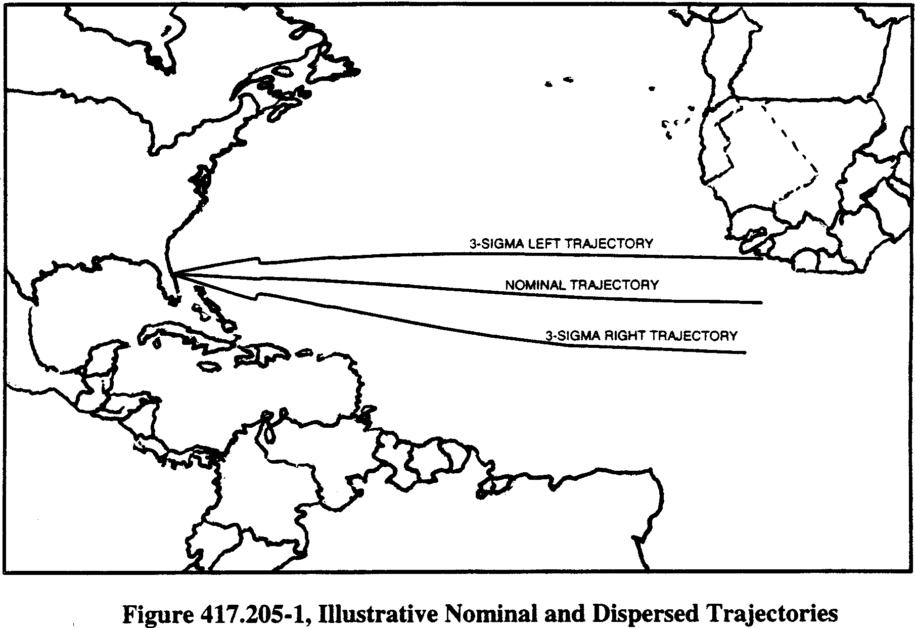
(b) Wind standards. A trajectory analysis shall incorporate wind data developed in accordance with the wind analysis in § 417.217 and in accordance with the following:
(1) A launch operator shall compute “with-wind” launch vehicle trajectories pursuant to § 417.205(f)(6) using annual composite wind profiles. When a launch operator will launch only at a particular time period during the year the launch operator may use the monthly composite wind for that time period.
(2) A launch operator shall compute the annual composite wind profile with a cumulative percentile frequency that represents wind conditions that are at least as severe as the worst wind conditions under which flight would be attempted. These worst wind conditions must account for the launch vehicle's ability to operate normally in the presence of wind and accommodate any flight safety limit constraints.
(c) Nominal trajectory. A launch operator shall compute a nominal trajectory that describes a launch vehicle's flight path, position and velocity, assuming all vehicle aerodynamic parameters are as expected, all vehicle internal and external systems perform exactly as planned, and there are no external perturbing influences other than atmospheric drag and gravity.
(d) Dispersed trajectories. A launch operator shall compute the following dispersed trajectories and describe a launch vehicle's position and velocity as a function of winds and three-sigma performance in the uprange, downrange, left-crossrange and right-crossrange directions.
(1) Three-sigma maximum and minimum performance trajectories. A launch operator shall compute a three-sigma maximum performance trajectory that provides the maximum downrange distance of the instantaneous impact point for any given time after lift-off. A launch operator shall compute a three-sigma minimum performance trajectory that provides the minimum downrange distance of the instantaneous impact point for any given time after lift-off. For any time after lift-off, the flight of a normally performing launch vehicle that is subjected to the assumed wind, shall have three-sigma impact dispersion, assuming a normal bivariate Gaussian distribution, lying between the extremes achieved at that time by the three-sigma maximum performing and three-sigma minimum performing launch vehicles.
(i) In calculating the three-sigma maximum and minimum performance trajectories, a launch operator shall use annual composite head wind and annual composite tail wind profiles that represent the worst wind conditions under which a launch would be attempted as described in accordance with paragraph (b)(2) of this section.
(ii) The three-sigma maximum and minimum performance trajectories must account for all launch vehicle performance error parameters that have a significant effect upon instantaneous impact point range. A launch operator shall identify these parameters and incorporate them into the analysis in accordance with paragraph (f)(1) of this section.
(2) Three-sigma left and right lateral trajectories. A launch operator shall compute a three-sigma left lateral trajectory that provides the maximum left crossrange distance of the instantaneous impact point for any given time after lift-off. A launch operator shall compute a three-sigma right lateral trajectory that provides the maximum right crossrange distance of the instantaneous impact point for any given time after lift-off. For any time-after-liftoff, the instantaneous impact point ground trace for three-sigma of all normally performing vehicles, assuming a normal bivariate Gaussian distribution, subjected to the assumed winds, must lie between the three-sigma left lateral instantaneous impact point ground trace and the three-sigma right lateral instantaneous impact point ground trace.
(i) In calculating each left and right lateral trajectory, composite left and composite right lateral-wind profiles Start Printed Page 63990shall be used which represent the worst wind conditions for which a launch would be attempted as required by paragraph (b)(2) of this section.
(ii) The three-sigma left and right lateral trajectories must account for the launch vehicle performance error parameters that have a significant effect upon the lateral deviation of the instantaneous impact point. A launch operator shall identify these performance error parameters and incorporate them into the analysis in accordance with paragraph (f)(1) of this section.
(3) Fuel-exhaustion trajectory. A launch operator shall compute a fuel exhaustion trajectory that is an extension of either the nominal trajectory taken through fuel exhaustion or the three-sigma maximum trajectory taken through fuel exhaustion, whichever of the two trajectories produces instantaneous impact points with the greatest range for any given time-after-liftoff. The fuel exhaustion trajectory shall be determined in accordance with the following:
(i) Trajectory data through fuel exhaustion is required even if a programmed thrust termination is scheduled in advance of fuel exhaustion.
(ii) For sub-orbital flights, fuel exhaustion trajectory data need only be determined for the last stage. Any previous stage is assumed to have nominal or three-sigma maximum performance as described by paragraph (d)(3) of this section.
(iii) For orbital flights, the fuel exhaustion trajectory data need only be determined for the last suborbital stage. Any previous stage is assumed to have nominal or three-sigma maximum performance as described by paragraph (d)(3) of this section.
(iv) The wind constraints for a fuel exhaustion trajectory shall be the same as those that apply to the nominal or three-sigma trajectory used to compute the fuel exhaustion trajectory.
(e) Straight-up trajectory. A launch operator shall compute a straight-up trajectory, beginning at the planned time of ignition, which simulates a malfunction that causes the launch vehicle to fly its entire flight in a vertical or near vertical direction above the launch point. The amount of time that a straight-up trajectory lasts must be no less than the sum of the straight-up time determined in accordance with § 417.215 plus the duration of a potential malfunction turn determined in accordance with § 417.207(b)(2).
(f) Analysis process and computations. A launch operator shall use a six-degree-of freedom trajectory model to generate each required three-sigma trajectory in terms of instantaneous impact point distance from the nominal location. In the course of generating each trajectory a launch operator shall use a root-sum-square trajectory analysis method that satisfies the requirements of paragraphs (f)(1) through (6) of this section or may employ an alternate method, such as a Monte Carlo analysis, if the launch operator demonstrates clearly and convincingly through the licensing process that its alternate method provides an equivalent level of safety. When using the root-sum-square method, a launch operator shall:
(1) Performance error parameters. Identify individual launch vehicle performance error parameters that contribute to the dispersion of the launch vehicle's instantaneous impact point. A launch operator shall identify all launch vehicle performance error parameters and any standard deviations for each parameter that reflect launch vehicle performance variations and any external forces that can cause offsets from the nominal trajectory during normal flight. Each dispersed trajectory must account for these performance error parameters. The performance error parameters must include thrust; thrust misalignment; specific impulse; weight; variation in firing times of the stages; fuel flow rates; contributions from the guidance, navigation, and control systems; steering misalignment; and winds.
(2) No-wind trajectory simulation. Perform a series of no-wind trajectory simulation runs using a six degree-of-freedom model. Each trajectory simulation run must introduce no more than one three-sigma value of a performance error parameter while all other parameters are held at nominal levels.
(3) Tabulate individual instantaneous impact point deviations. Tabulate at even one-second intervals, the individual downrange, uprange, left-crossrange, and right-crossrange instantaneous impact point deviations from the nominal instantaneous impact point location caused by each three-sigma value of the performance error parameters.
(4) Combine individual instantaneous impact point deviations. For each one-second interval, for each downrange, uprange, left crossrange, and right crossrange direction calculate the square root of the sum of the squares of all the individual instantaneous impact point deviations for each direction. The resulting values for downrange, uprange, left crossrange, and right crossrange represent the three-sigma maximum, minimum, left lateral, and right lateral instantaneous impact point deviations, respectively.
(5) No-wind matching trajectories. By further trajectory simulation, generate four thrusting flight no-wind trajectories that match the three-sigma instantaneous impact point deviations calculated in accordance with paragraph (f)(4) of this section.
(6) With-wind three-sigma trajectories. Generate each three-sigma trajectory using the worst wind conditions determined in accordance with paragraph (b) of this section and the launch vehicle performance error parameters and magnitudes used to generate the no-wind matching trajectories in accordance with paragraph (f)(5) of this section. The effect of winds on the three-sigma trajectory must be modeled from liftoff through the point in flight where the launch vehicle attains an altitude where the wind no longer affects the launch vehicle.
(g) Trajectory analysis products. A launch operator shall submit the products of its trajectory analysis to the FAA in accordance with § 417.203(c). Those products shall include the following:
(1) Assumptions and procedures. A description of all assumptions, procedures and models used in deriving the nominal and dispersed trajectories, with particular attention to the six-degrees-of-freedom model.
(2) Three-sigma launch vehicle performance error parameter(s). A description of the three-sigma performance error parameters accounted for by a trajectory analysis and each parameter's standard deviations determined in accordance with paragraph (f)(1) of this section.
(3) Wind profile(s). A graph and tabular listing of the annual winds required by paragraph (b)(1) of this section and the worst case winds required by paragraph (b)(2) of this section. The graph and tabular wind data must be the same as that used in performing the trajectory analysis and must provide wind magnitude and direction as a function of altitude for the air space regions from the Earth's surface to 100,000 feet in altitude for the area intersected by the launch vehicle trajectory. Altitude intervals must not exceed 1000 feet. Statistical wind geographic reference points shall not exceed spatial intervals greater than 2.5 degrees latitude or 2.5 degrees longitude. The graphical and tabular data shall conform to the presentation requirements of § 417.217(d)(1)(i) and § 417.217(d)(1)(ii), respectively. Start Printed Page 63991
(4) Launch azimuth. The azimuthal direction of the trajectory's “X-axis” at liftoff measured clockwise in degrees from true north.
(5) Launch point. Identification and location of the proposed launch point, including its name, geodetic latitude (+N), longitude (+E), and geodetic height.
(6) Reference ellipsoid. The name of the reference ellipsoid that the launch operator uses in performing trajectory analysis to approximate the average curvature of the Earth and the length of semi-major axis, length of semi-minor axis, flattening parameter, eccentricity, gravitational parameter, and angular velocity of the Earth at the equator. If the reference ellipsoid is not a WGS-84 ellipsoidal Earth model, the applicant shall submit the equations needed to convert the submitted ellipsoid information to the WGS-84 ellipsoid.
(7) Temporal trajectory items. A launch operator shall provide the following temporal trajectory data for time intervals not in excess of one second and for the discrete time points that correspond to each jettison, ignition, burnout, and thrust termination of each stage. For a sub-orbital launch vehicle, these data must account for the weight of any and all payloads to be flown and the planned nominal quadrant elevation angles of the vehicle's launcher. These data must be provided on paper in text format or electronically via disk files. The text format must have a column for each data item and a row for each time point. Disk files must be in ASCII text, space delimited format, with a column for each data item and a row for each time point. An electronic “readme” file shall be provided that clearly identifies the data, and their units of measure, in the individual disk files.
(i) Trajectory time-after-liftoff. Time-after-liftoff is measured from first motion of the first thrusting stage of the launch vehicle. The first motion time is identified as T-0 and shall be tabulated as the “0.0” time point on the trajectory.
(ii) Launch Vehicle Direction Cosines. The direction cosines of the roll axis, pitch axis, and yaw axis. The roll axis is a line identical to the launch vehicle's longitudinal axis with its origin at the nominal center of gravity positive towards the vehicle nose. The roll plane is normal to the roll axis at the vehicle's nominal center of gravity. The yaw axis and the pitch axis are any two orthogonal axes lying in the roll plane, and are chosen at the launch operator's discretion. Roll, pitch and yaw axes must be right-handed systems so that, when looking along the roll axis toward the nose, a clockwise rotation around the roll axis will send the pitch axis toward the yaw axis. The right-handed system must be oriented such that the yaw axis is positive in the downrange direction while in the vertical position (roll axis upward from surface) or positive at an angle of 180 degrees to the downrange direction. The axis may be related to the vehicle's normal orientation with respect to the vehicle's trajectory but, once defined, remain fixed with respect to the vehicle's body. The launch operator shall indicate the positive direction of the yaw axis chosen. The reference system for the direction cosines shall be the EFG system described in paragraph (g)(7)(iv) of this section.
(iii) X, Y, Z, XD, YD, ZD trajectory coordinates. The launch vehicle position coordinates (X, Y, Z) and velocity magnitudes (XD, YD, ZD) must be referenced to an orthogonal, Earth-fixed, right-handed coordinate system. The XY-plane must be tangent to the ellipsoidal Earth at the origin, which is the launch point, the positive X-axis must coincide with the launch azimuth, the positive Z-axis must be directed away from the ellipsoidal Earth, and the Y-axis must be positive to the left looking downrange.
(iv) E, F, G, ED, FD, GD trajectory coordinates. The launch vehicle position coordinates (E, F, G) and velocity magnitudes (ED, FD, GD) must be referenced to an orthogonal, Earth fixed, Earth centered, right-handed coordinate system. The origin of the EFG system must be at the center of the reference ellipsoid. The E and F axes lie in the plane of the equator and the G-axis coincides with the rotational axis of the Earth. The E-axis is positive through 0° East longitude (Greenwich Meridian), the F-axis is positive through 90° East longitude, and the G-axis is positive through the North Pole. This system is non-inertial and rotates with the Earth.
(v) Resultant Earth-fixed velocity. The square root of the sum of the squares of the XD, YD, and ZD components of the trajectory state vector.
(vi) Path angle of velocity vector. The angle between the local horizontal plane and the velocity vector measured positive upward from the local horizontal. The local horizontal is a plane tangent to the ellipsoidal Earth at the sub-vehicle point.
(vii) Sub-vehicle point. Sub-vehicle point coordinates include present position geodetic latitude (+N) and present position longitude (+E). These coordinates are found at each trajectory time on the surface of the ellipsoidal Earth model and are located at the intersection of the line normal to the ellipsoid and passing through the launch vehicle center of gravity.
(viii) Altitude. The distance from the sub-vehicle point to the launch vehicle's center of gravity.
(ix) Present position arc-range. The distance measured along the surface of the reference ellipsoid, from the launch point to the sub-vehicle point.
(x) Total weight. The sum of the inert and propellant weights for each time point on the trajectory.
(xi) Total thrust. This thrust is a scalar quantity.
(xii) Instantaneous impact point data. These data include instantaneous impact point geodetic latitude (+N), instantaneous impact point longitude (+E), instantaneous impact point arc-range, and time to instantaneous impact. The instantaneous impact point arc-range is the distance, measured along the surface of the reference ellipsoid, from the launch point to the instantaneous impact point. The time to instantaneous impact is the vacuum flight time remaining to impact, assuming all thrust is terminated at the associated time-after-liftoff.
(xiii) Dynamic pressure as a function of time-of-flight. Tabular data as part of the temporal trajectory items and a two-dimensional graph, with time-of-flight on the X-axis and dynamic pressure on the Y-axis.
(xiv) Coriolis displacement. The geodetic distance from the instantaneous impact point to the displacement point caused by Coriolis accelerations if this effect is not included in the trajectory computations.
(8) Conditions for guided expendable launch vehicles. For guided expendable launch vehicles, all trajectories must be provided from launch up to a point in flight where effective thrust of the final stage has terminated, or to thrust termination of the stage or burn that places the vehicle in orbit.
(9) Conditions for unguided expendable launch vehicles. For unguided expendable launch vehicles, trajectories shall be provided from launch until burnout of the final stage for each nominal quadrant elevation angle and payload weight. Time steps of the trajectory must be at even intervals, not to exceed one second increments during thrusting flight, and for discrete times corresponding to each jettison, ignition, burnout, and thrust termination of each stage. If any stage burn time is less than four seconds, time intervals must be reduced to 0.2 seconds or less.
Malfunction turn analysis.(a) General. A launch operator shall perform a malfunction turn analysis to Start Printed Page 63992determine a launch vehicle's greatest turning capability as a function of trajectory time. A launch operator shall use the products of its malfunction turn analysis as input to its flight safety limits analysis and other analysis where it is necessary to determine how far a launch vehicle's impact point can deviate from the nominal impact point when a malfunction occurs. A launch operator shall determine the set of launch vehicle velocity vector angular deviations, measured from the nominal launch vehicle velocity vector, that cause deviation from the nominal instantaneous impact point. The velocity vector angular deviations shall be determined as a function of time, beginning at the malfunction start time. A launch operator shall also determine the corresponding change in launch vehicle velocity magnitude from the nominal velocity magnitude, as a function of time, beginning at the malfunction start time.
(b) Malfunction turn analysis constraints. A launch operator shall apply the following constraints to a malfunction turn analysis:
(1) A launch operator shall determine a flight safety system time delay in accordance with § 417.223 and use the results to determine the required malfunction turn duration in accordance with paragraph (b)(2) of this section.
(2) A malfunction turn shall start at a given malfunction start time and have a duration of no less than 12 seconds or the product of 1.2 times the flight safety system time delay, whichever is greater. These duration limits apply regardless of whether or not the vehicle would break up or tumble before the prescribed duration of the turn.
(3) A malfunction turn analysis must cover the thrusting periods of flight along a nominal trajectory. Malfunction turn data are required for all trajectory times from ignition to thrust termination of the final thrusting stage or until the launch vehicle achieves orbital velocity (orbital insertion), whichever occurs first.
(4) A malfunction turn must be a 90-degree turn or a turn in both the pitch and yaw planes that would produce the largest deviation from the nominal instantaneous impact point of which the launch vehicle is capable at any time during the malfunction turn. A 90-degree turn is a turn produced at the malfunction start time by instantaneously re-directing and maintaining the vehicle's thrust at 90 degrees to the velocity vector, without regard for how this situation can be brought about. A launch operator shall determine the type of turn to use as a malfunction turn in accordance with paragraph (d) of this section. If a launch operator elects not to use a 90-degree turn, the following types of turns apply when determining the malfunction turn in accordance with paragraph (d) of this section:
(i) Pitch turn. A pitch turn is the angle turned by the launch vehicle's total velocity vector in the pitch-plane. The velocity vector's pitch-plane is the two dimensional surface that includes the launch vehicle's yaw-axis and the launch vehicle's roll-axis. Figure 417.207-1 shows relative spatial relationships between the pitch plane, acceleration vector (Ao), initial velocity vector (Vo), malfunction turn velocity vector (Vturn), angle of attack (α), and malfunction turn angle (θ). The depiction of the acceleration vector, as shown in Figure 417.207-1, was simplified by aligning it with the roll axis.

(ii) Yaw turn. A yaw turn is the angle turned by the launch vehicle's total velocity vector in the lateral plane. The velocity vector's lateral plane is the two dimensional surface that includes the launch vehicle's pitch axis and the launch vehicle's total velocity vector. Figure 417.207-2 shows relative spatial relationships between the lateral turn plane, acceleration vector (Ao), initial velocity vector (Vo), malfunction turn velocity vector (Vturn), angle of attack (α), and malfunction turn angle (θ). The depiction of the acceleration vector, as shown in Figure 417.207-2, was simplified by aligning it with the roll axis. The launch operator shall measure Start Printed Page 63993the angle of attack between the roll axis and the velocity vector.

(iii) Trim turn. A trim turn is a turn where a launch vehicle's thrust moment balances the aerodynamic moment while a constant rotation rate is imparted to the launch vehicle's longitudinal axis. A maximum-rate trim turn is made at or near the greatest angle of attack that can be maintained while the aerodynamic moment is balanced by the thrust moment, whether the vehicle is stable or unstable.
(iv) Tumble turn. A tumble turn is a turn that results if the launch vehicle's airframe rotates in an uncontrolled fashion, at an angular rate that is brought about by a thrust vector offset angle, which is held constant throughout the turn. A series of tumble turns, each turn with a different thrust vector offset angle, shall be plotted on the same graph for a given malfunction start time.
(v) Turn envelope. A turn envelop is a curve on a tumble turn graph that has tangent points to each individual tumble turn curve computed for a given malfunction start time. This curve envelops the actual tumble turn curves giving a prediction of tumble turn angle for data areas between the calculated turn curves. This envelope is required because an infinite number of thrust vector deviation angles is possible and it is impractical to produce a curve for each deviation angle. Figure 417.207-3 depicts a series of tumble turn curves and the tumble turn envelope curve.
Start Printed Page 63994
(5) A launch operator's first malfunction turn start time must not be greater than the nominal trajectory time corresponding to the earliest destruct time determined in accordance with § 417.221 minus the flight safety system delay time determined in accordance with § 417.223. Subsequent malfunction turns shall be initiated at regular nominal trajectory time intervals not to exceed the flight safety system delay time.
(6) A malfunction turn analysis must provide malfunction turn computation intervals of one second over the duration of each malfunction turn.
(7) For the purposes of performing the various malfunction turn computations, a launch operator shall assume that the launch vehicle performance is nominal up to the point of the malfunction that produces the turn.
(8) A launch operator shall not include the effects of gravity in a malfunction turn analysis, unless a launch operator ensures that there is no duplication of gravity effects by any other dependent analysis that uses the products of the malfunction turn analysis as input. Other analyses that may account for gravity effects include, but need not be limited to, the flight safety limits analysis (§ 417.213), data lose flight time analysis (§ 417.221), toxic release hazard analysis (§ 417.229), distant focus overpressure blast effects risk analysis (§ 417.231), hazard areas analysis (§ 417.225), and debris risk analysis (§ 417.227).
(9) A launch operator shall evaluate both pitch and yaw turns for malfunction start times that correspond to each sub-vehicle point. A launch operator shall use the velocity vector turn angle rate that causes the largest dispersion, from either the pitch or yaw turn computations, in the development of flight safety limits. If the pitch turn angle and yaw turn angle are the same except for the effects of gravity, the yaw turn angles may be determined from pitch calculations that, in effect, have had the gravity component subtracted out at each step in the computations.
(10) A launch operator's malfunction turn analysis shall ensure the tumble turn envelope curve maintains a positive slope throughout the malfunction turn duration as illustrated in figure 417.207-3. A launch operator may encounter a known difficulty with calculating tumble turns for an aerodynamically unstable launch vehicle. In the high aerodynamic region it often turns out that no matter how small the initial deflection of the rocket engine, the airframe tumbles through 180 degrees, or one-half cycle, in less time than the required turn duration period. In such a case, the launch operator shall use a 90-degree turn as the malfunction turn.
(c) Failure modes. A malfunction turn analysis must evaluate the significant failure modes that result in a thrust vector offset from the nominal state. If the malfunction turn at a given malfunction start time can occur as a function of more than one failure mode, the launch operator must evaluate the malfunction turn for the mode causing the most rapid and largest launch vehicle instantaneous impact point deviation. Failure modes will vary as a function of flight time. The same set of failure modes shall be used for each malfunction start time where applicable to that point of a vehicle's flight.
(d) Determining type of malfunction turn to use. A launch operator shall establish the maximum turning capability of a launch vehicle's velocity vector based on an evaluation of trim turns and tumble turns, in both the pitch and yaw planes, or a 90-degree turn. The different types of turns are defined in paragraph (b)(4) of this section. When computing malfunction turn angles on the basis of a 90-degree turn, a launch operator shall ensure that its flight safety plan, including the flight corridor, flight safety limits, and mission rules reflect the conservative safety buffers that result from using this approach. When not using a 90-degree turn, a launch operator shall establish the launch vehicle maximum turning capability in accordance with the following malfunction turn capabilities:
(1) Launch vehicle stable at all angles of attack. If a launch vehicle is so stable Start Printed Page 63995that the maximum thrust moment cannot produce tumbling, but produces a maximum-rate trim turn at some angle of attack less than 90 degrees, the launch operator shall determine a series of trim turns, including the maximum-rate trim turn, by varying the initial thrust vector offset at the beginning of the turn. If the maximum thrust moment results in a maximum-rate trim turn at some angle of attack greater than 90 degrees, a launch operator shall determine a series of trim turns for angles of attack up to and including 90 degrees.
(2) Launch vehicle aerodynamically unstable at all angles of attack. During the part of launch vehicle flight where the maximum trim angle of attack is small, tumble turns may result in the greatest malfunction turn angles. If the maximum trim angle of attack is large, trim turns may lead to higher malfunction turn angles than tumble turns. If the launch operator clearly and convincingly demonstrates that flying a trim turn even for a period of only a few seconds is impossible, the malfunction turn analysis need only determine tumble turns. Otherwise, the launch operator's malfunction turn analysis must determine a series of trim turns, including the maximum-rate trim turn, and the family of tumble turns.
(3) Launch vehicle unstable at low angles of attack but stable at some higher angles of attack. If large engine deflections result in tumbling, and small engine deflections do not, a series of trim and tumble turns shall be generated as required by paragraph (d)(2) of this section for launch vehicles aerodynamically unstable at all angles of attack. If both large and small constant engine deflections result in tumbling, regardless of how small the deflection might be, the malfunction turn capabilities achieved at the stability angle of attack, assuming no upsetting thrust moment, shall be used in addition to the turns achieved by a tumbling vehicle. This situation arises because the stability at high angles of attack is insufficient to arrest the angular velocity, which is built up during the initial part of a tumble turn where the launch vehicle is unstable. Although the launch vehicle cannot arrive at this stability angle of attack as a result of the constant engine deflection, there is some deflection behavior, such as a deflection rate, that will produce this result. If a launch operator determines that arriving at such a deflection program is too difficult or too time consuming, the launch operator may assume that the launch vehicle instantaneously rotates to the trim angle of attack and stabilizes at this point. In such a case, tumble turn angles may be used during that part of launch vehicle flight for which the tumble turn envelope curve maintains a positive slope throughout the duration of the computation.
(e) Malfunction turn analysis products. The products of a launch operator's malfunction turn analysis to be submitted to the FAA in accordance with § 417.203(c) must include the following:
(1) A description of the assumptions, techniques, and equations used in deriving the malfunction turns.
(2) A set of sample calculations for at least one flight hazard area malfunction start time and one downrange malfunction start time. The sample computation for the downrange malfunction start time shall be at least 50 seconds greater than the flight hazard area malfunction start time or at the time of nominal thrust termination of the final stage minus the malfunction turn duration.
(3) A description of how any yaw turn angles were developed from pitch turn computations as described in paragraph (b)(9) of this section.
(4) A launch operator shall submit malfunction turn data in tabular and graphic formats. Scale factors of graphs must be selected so the plotting and reading accuracy do not degrade the accuracy of the data. For each malfunction turn start time, the time scales on malfunction velocity vector turn angle and malfunction velocity magnitude plot pairs shall be the same. Tabular listings of the data used to generate the graphs are required in digital ASCII file format. A launch operator shall submit the data items required in this paragraph for each malfunction start time. These data must be provided at intervals of one second or less over the malfunction turn duration
(i) Velocity turn angle graphs. For each malfunction turn angle graph, the ordinate axis must represent the total angle turned by the velocity vector, and the abscissa axis must represent the time duration of the turn. The abscissa must be divided into one-second increments. A launch operator shall submit a graph for each malfunction start time. The series of tumble turns shall include the envelope of all tumble turn curves. The tumble turn envelope shall represent the tumble turn capability for all possible constant thrust vector offset angles (or other parameter). For this case, plots of each tumble turn curve selected to define the envelope are required on the same graph with the envelope. For trim turns, a series of trim turn curves for representative values of thrust vector offset (or other parameter) is required. The series of trim turn curves shall include the maximum-rate trim turn. Figure 417.207-4 depicts an example family of tumble turn curves and the tumble turn velocity vector envelope.
(ii) Velocity magnitude graphs. For each malfunction velocity magnitude graph, the ordinate axis must represent the magnitude of the velocity vector and the abscissa axis must represent the time duration of the turn. The abscissa must be divided into one-second increments. A launch operator shall submit a graph for each malfunction start time. The total velocity magnitude shall be plotted as a function of time after the malfunction start time for each thrust vector offset (or other parameter) used to define the corresponding velocity turn-angle curve. A corresponding velocity magnitude curve is required for each velocity tumble-turn angle curve and each velocity trim-turn angle curve. For each individual tumble turn curve selected to define the tumble turn envelope, its point of tangency to the envelope shall be indicated on the corresponding velocity magnitude graph. The point of tangency is the point where the tumble turn envelope is tangent to an individual tumble turn curve produced with a discrete thrust vector offset angle (or other parameter). Transposing the points of tangency to the velocity magnitude curves is accomplished by plotting a point on the velocity magnitude curve at the same time point where tangency occurs on the corresponding velocity tumble-turn angle curve. Figure 417.207-5 depicts an example tumble turn velocity magnitude curve.
Start Printed Page 63996
Start Printed Page 63997
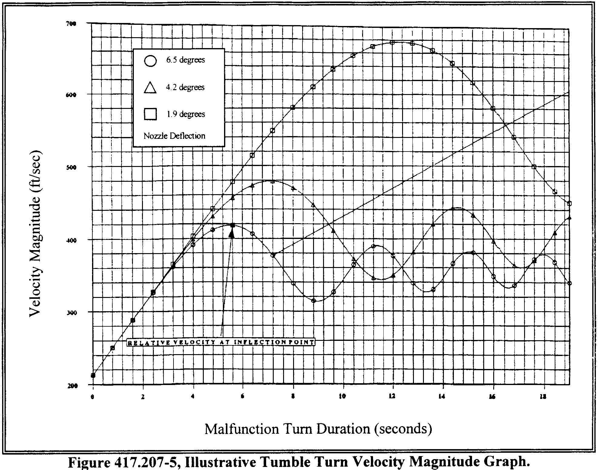
(iii) Vehicle orientation. If thrust-augmenting rocket motors are used on a launch vehicle, the launch operator shall submit tabular or graphical data for the vehicle attitude in the form of roll, pitch, and yaw angular orientation of the vehicle longitudinal axis as a function of time into the turn for each turn initiation time. Angular orientation of a launch vehicle's longitudinal axis is illustrated in figures 417.207-6 and 417.207-7.
Start Printed Page 63998
Start Printed Page 63999
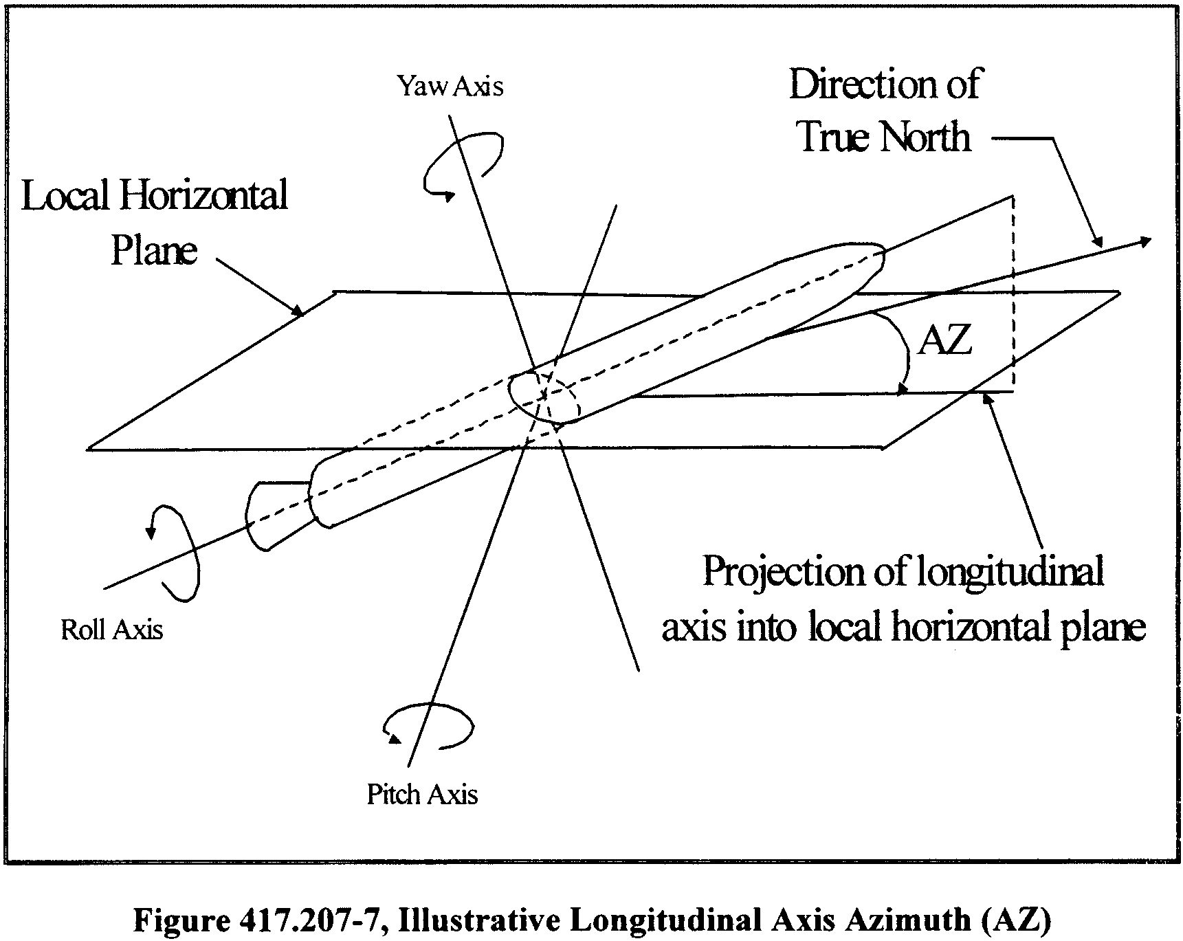
(iv) Onset conditions. A launch operator shall provide launch vehicle state information for each malfunction start time. This state data shall include the launch vehicle thrust, weight, velocity magnitude and pad-centered topocentric X, Y, Z, XD, YD, ZD state vector.
(v) Breakup information. A launch operator shall specify if its launch vehicle will remain intact throughout each malfunction turn. If the launch vehicle will breakup during a turn, then the time for launch vehicle breakup must be indicated on the velocity magnitude graphs. The time into the turn at which vehicle breakup would occur must be either a specific value or a probability distribution for time to breakup.
(vi) Inflection point. A launch operator shall indicate the inflection point on each tumble turn envelope curve and maximum rate trim turn curve for each malfunction start time as illustrated in figure 417.207-4. The inflection point marks the point in time during the turn where the slope of the curve stops increasing and begins to decrease or, in other words, the point where the concavity of the curve changes from concave up to concave down. The inflection point on a malfunction turn curve indicates the time in the malfunction turn that the launch vehicle body achieves a 90-degree rotation from the nominal position. On a tumble turn curve the inflection point represents the start of the launch vehicle tumble.
(vii) Gravity effects. A launch operator's malfunction turn analysis products must identify whether the malfunction turn analysis accounts for the effects of gravity. If the malfunction turn analysis accounts for the effects of gravity, the products must include a demonstration of how the analysis satisfies paragraph (b)(8) of this section.
Debris analysis.(a) General. A launch operator shall perform a debris analysis that identifies inert, explosive and other hazardous launch vehicle debris resulting from a launch vehicle malfunction and from any planned jettison of launch vehicle components for orbital and sub-orbital launch.
(b) Debris analysis constraints. A debris analysis must produce the debris models described in paragraphs (c) and (d) of this section, in the form of lists of debris that results from breakup of a launch vehicle and any planned jettison of debris or components. Each list must describe each debris fragment produced, including its physical characteristics, whether it is inert or explosive, and the effects of impact, such as explosive overpressure, skip, splatter, or bounce radius. Each debris list must be produced in accordance with the following:
(1) A debris analysis must account for launch vehicle breakup caused by the activation of any flight termination system in accordance with the following:
(i) A debris analysis must account for the effects of debris produced when an intact malfunctioning vehicle is destroyed by flight termination system activation.
(ii) A debris analysis must account for spontaneous breakup of the launch vehicle assisted by the action of any inadvertent separation destruct system included as part of a flight termination system.
(iii) A debris analysis must account for the effects of debris produced when a flight termination system is activated after inadvertent breakup of the launch vehicle.
(2) A debris analysis must account for debris due to any malfunction where the launch vehicle's structural integrity limits may be exceeded.
(3) A debris analysis must account for the immediate post-breakup or jettison Start Printed Page 64000environment of the launch vehicle debris, any change in debris characteristics over time from launch vehicle break-up or jettison to debris impact, and the effects of the debris upon impact.
(4) A debris analysis must account for the impact overpressure, fragmentation, and secondary debris effects of any confined or unconfined solid propellant chunks and fueled components containing either liquid or solid propellants that could survive to impact, as a function of vehicle malfunction time.
(5) A debris analysis must account for the effects of impact of the intact vehicle as a function of failure time. The intact impact debris analysis must identify the trinitrotoluene (TNT) yield of impact explosions, and the numbers of fragments projected from all such explosions, including non-launch vehicle ejecta and the blast overpressure radius. The TNT yield of impact explosion may be estimated from several models. The input to these models must include the propellant weight at impact, the impact speed, the orientation of the propellant, and the impacted surface material. Figure 417.209-1 shows the generic relationship between impact speed and TNT yield. A launch operator shall identify the impact yield relationship for its launch vehicle propellant for use in the debris analysis.

(c) Debris model. A debris analysis must produce a model of the debris resulting from unplanned breakup of a launch vehicle for use as input to other analyses, such as establishing flight safety limits and hazard areas and performing debris risk, toxic, and blast analyses. A launch operator's debris model must satisfy the following:
(1) Debris fragments. A debris model must contain debris fragment data for the launch vehicle flight period from the planned ignition time until the launch vehicle achieves orbital velocity for an orbital launch. For a sub-orbital launch, the debris model must contain debris fragment data for the launch vehicle flight period from the planned ignition time up to thrust termination of the last thrusting stage.
(2) Inert fragments. A debris model must identify all inert fragments that are not volatile and that could not burn or explode. A debris model must identify inert fragments for each breakup time during flight corresponding to a critical event when the fragment catalog is significantly changed by the event. Critical events include staging, payload fairing jettison, or other normal hardware jettison activities.
(3) Explosive and non-explosive propellant fragments. A debris model must identify all propellant fragments that are explosive or non-explosive upon impact. The debris model must describe each propellant fragment as a function of time, from the time of breakup through ballistic free-fall to impact. The data shall describe the fragment characteristics, including its weight, at the time of breakup and at the time of impact. The fall time characteristics shall be described as a function of time, such as burn rate under ambient atmospheric conditions. The time frequency of the data must represent the rate at which the fragment characteristics change so as not to reduce the accuracy of the data. The debris model shall identify the following types of propellant fragments:
(i) Un-contained non-explosive solid propellant fragment. Solid propellant that is exposed directly to the atmosphere and that could burn but not explode upon impact.
(ii) Contained non-explosive propellant fragment. Solid or liquid propellant that is enclosed in a container, such as a motor case or pressure vessel, and that could burn but not explode upon impact.
(iii) Contained explosive propellant fragment. Solid or liquid propellant that is enclosed in a container, such as a Start Printed Page 64001motor case or pressure vessel, and that will explode upon impact.
(iv) Un-contained explosive solid propellant fragment. Solid propellant that is exposed directly to the atmosphere and that will explode upon impact.
(4) Other non-inert debris fragments. In addition to the explosive and flammable fragments required by paragraph (c)(3) of this section, a debris model must identify any other non-inert debris fragments, such as toxic or radioactive fragments, that present any other hazards to the public.
(5) Fragment ballistic coefficient. A debris model must include the axial, transverse, and tumble orientation ballistic coefficient for each fragment's projected area as described in paragraph (c)(8) of this section.
(6) Fragment weight. At each modeled breakup time, the individual fragment weights must approximately add up to the total weight of inert material in the vehicle combined with the weight of contained liquid propellants and solid propellants that are not consumed in the initial breakup or conflagration.
(7) Fragment imparted velocity. A debris model must include the maximum velocity imparted to each fragment due to potential explosion or pressure rupture. Unless otherwise defined by the launch operator, the velocity shall be modeled with a Maxwellian distribution with the specified maximum value equal to the 97th percentile. If the velocity distribution is different than the Maxwellian, a launch operator shall define the distribution, including whether the specified maximum value is interpreted as a fixed value with no uncertainty.
(8) Fragment projected area. A debris model must include the planform area of the fragment normal to the drag force at the stability angle of attack. If the fragment will not stabilize, the projected area is the tumble area normal to the drag force.
(9) Fragment effective casualty area. A debris model must identify the effective casualty area of each debris fragment. For inert fragments and non-explosive propellant fragments the casualty area must account for the size of the fragment, the path angle of the fragment trajectory at impact, the effects of slide, bounce and splatter produced from hard and soft surfaces, and whether a non-explosive propellant fragment is contained or un-contained. For explosive propellant fragments the effective casualty area must account for blast overpressure, non-explosive remains, ejecta originating from the impact location, and whether the propellant fragment is contained or un-contained. For other non-inert fragments, such as toxic or radioactive fragments, the effective casualty area must account for the diffusion, dispersion, deposition, radiation or other hazard exposure characteristics of the non-inert debris and must be a circle that is defined by a hazard radius for the non-inert fragment.
(10) Debris fragment count. A debris model must include the total number of each type of fragment listed in paragraphs (c)(2), (c)(3), and (c)(4) of this section resulting from a malfunction.
(11) Fragment classes. A launch operator shall categorize malfunction debris fragments into classes where the hazards associated with the mean fragment in each class conservatively represent the hazards for every fragment in the class. A launch operator shall define fragment classes as one or more fragments whose characteristics are similar enough to allow all the fragments in the class to be described and treated by a single average set of characteristics. Fragments shall be categorized into classes in accordance with the following:
(i) A launch operator shall use fragment type as the primary parameter for categorizing fragments. All fragments within a class must be of the same type as defined in paragraphs (c)(2), (c)(3), and (c)(4) of this section.
(ii) A launch operator shall use the debris subsonic ballistic coefficient (βsub) as the secondary parameter for categorizing fragments. A launch operator shall keep the difference of the smallest log10 10(βsub) value from the largest log10 10(βsub) value in a class less than 0.5.
(iii) A launch operator shall use the breakup-imparted velocity (ΔV) as the tertiary parameter for categorizing fragments. Fragments shall be categorized as a function of the range of ΔV for the fragments within a class and the class's median subsonic ballistic coefficient. For each class, a launch operator shall keep the ratio of the maximum breakup-imparted velocity (ΔVmax) to minimum breakup-imparted velocity (ΔVmin) within the following bound:

Where: β′sub is the median subsonic ballistic coefficient for the fragments in a class.
(d) Jettisoned body model. A launch operator's debris analysis must produce a jettisoned body model of the launch vehicle debris resulting from scheduled launch vehicle events for use as input to other analyses, such as the flight safety limits, hazard areas, and debris risk analyses. Jettisoned bodies include, but need not be limited to, stages, payload fairings, thrust reversal ports, solid rocket motors, attach fittings and associated hardware components. A jettisoned body model must include, but need not be limited to the following:
(1) Jettisoned body fragment count. The number of each type of jettisoned body resulting from a specific scheduled jettison.
(2) Re-entry breakup. If the jettisoned body breaks up during reentry, the launch operator's debris model must include an estimate of the number of debris fragments, their approximate weights, projected areas, and ballistic coefficients.
(3) Jettison flight time. The time from liftoff during normal flight that each jettison is planned to occur.
(4) Weights. Total weight of each jettisoned body at the time it is jettisoned.
(5) Projected area. The stability angle of attack planform area of the jettisoned body normal to the drag force. If the jettisoned body will not stabilize, the projected area is the tumble area normal to the drag force.
(6) Ballistic coefficient. The axial, transverse, and tumble orientation ballistic coefficient for each fragment's projected area as identified in accordance with paragraph (d)(5) of this section.
(e) Debris analysis products. A launch operator shall submit the products of its debris analysis to the FAA in accordance with § 417.203(c). Those products shall include the following:
(1) Multiple fragment lists. Lists of fragments that identify the variation of the fragment characteristics with breakup time.
(2) Fragment descriptions. A description of the fragments contained in the launch operator's debris model required by paragraph (c) of this section. The description must identify the fragment as a launch vehicle part or component, describe its shape and dimensions and include any drawings.
(3) Minimum distance fragment. As a function of breakup time, identification of the fragment that, in the absence of winds, will travel the least distance in comparison to all other fragments.
(4) Intact impact TNT yield. For an intact impact of a launch vehicle, for each failure time, a launch operator shall identify the TNT yield of each impact explosion, blast overpressure radius, and the number of fragments projected from all such explosions including non-launch vehicle ejecta. Start Printed Page 64002
(5) Maximum distance fragment. As a function of breakup time, identification of the fragment that, in the absence of winds, will travel the greatest distance in comparison to all other fragments.
(6) Fragment class data. The class name, boundaries of the class grouping parameters, and the number of fragments in any fragment class established in accordance with paragraph (c)(11) of this section.
(7) Breakup altitude. For breakup due to aerodynamic loads, inertial loads, and atmospheric reentry, identification of the range of altitudes at which breakup may occur.
(8) Ballistic coefficient (β). The mean and plus and minus three-sigma values for each fragment. A launch operator shall include graphs of the coefficient of drag (Cd) as a function of Mach number for the nominal and three-sigma beta variations for each fragment shape. Each graph must be labeled with the shape represented by the curve and reference area used to develop the curve. A launch operator shall provide a Cd vs. Mach curve for any axial, transverse, and tumble orientations for fragments that will not stabilize during free-fall conditions. For fragments that may stabilize during free-fall, a launch operator shall provide Cd vs. Mach curves for the stability angle of attack. If the angle of attack where the fragment stabilizes is other than zero degrees, a launch operator shall provide both the coefficient of lift (CL) vs. Mach number and the Cd vs. Mach number curves. The equations for Cd vs. Mach curves shall also be provided.
(9) Pre-flight propellant weight. The initial preflight weight of solid and liquid propellant for each launch vehicle component that contains solid or liquid propellant.
(10) Normal propellant consumption. The nominal and plus and minus three-sigma solid and liquid propellant consumption rate, and pre-malfunction consumption rate for each component that contains solid or liquid propellant.
(11) Fragment weight. The mean and plus and minus three-sigma weight of each fragment.
(12) Projected area. The mean and plus and minus three-sigma axial, transverse, and tumbling areas for each fragment. This information is not required for those fragment classes classified as burning propellant classes as described in paragraph (e)(17) of this section.
(13) Imparted velocities. The maximum incremental velocity imparted to each fragment and the mean fragment of each fragment class created by flight termination system activation, or explosive or overpressure loads at breakup. The launch operator shall identify the velocity distribution as Maxwellian or shall define the distribution, including whether the specified maximum value is interpreted as a fixed value with no uncertainty.
(14) Fragment type. The fragment type for each fragment established in accordance with paragraphs (c)(2), (c)(3), and (c)(4) of this section.
(15) Effective casualty area. The effective casualty area established in accordance with paragraph (c)(9) of this section for each fragment and for the effective casualty area for the mean fragment of each fragment class.
(16) Stage of origination. The launch vehicle stage from which each fragment originated.
(17) Burning propellant classes. The propellant consumption rate for those fragments that burn during free-fall.
(18) Contained propellant fragments, explosive or non-explosive. For fragments defined as contained propellant fragments, whether explosive or non-explosive, a launch operator shall provide the initial weight of contained propellant and the consumption rate during free-fall. The initial weight of the propellant in a contained propellant fragment is the weight of the propellant before any of the propellant is consumed by normal vehicle operation or failure of the launch vehicle.
(19) Solid propellant fragment snuff-out pressure. The ambient pressure and the pressure at the surface of a solid propellant fragment, in pounds per square inch, required to sustain a solid propellant fragment's combustion during free-fall.
(20) Other non-inert debris fragments. For each non-inert debris fragment identified in accordance with paragraph (c)(4) of this section, a launch operator shall describe the diffusion, dispersion, deposition, radiation, or other hazard exposure characteristics used to determine the effective casualty area required by paragraph (c)(9) of this section.
(21) Residual thrust dispersion. For each thrusting or non-thrusting stage having residual thrust capability following a launch vehicle malfunction, a launch operator shall identify either the total residual impulse imparted or the full-residual thrust in foot-pounds as a function of break-up time. For any stage not capable of thrust after a launch vehicle malfunction, a launch operator shall identify the conditions under which the stage is no longer capable of thrust. For each stage that can be ignited as a result of a launch vehicle malfunction on a lower stage, a launch operator shall identify the effects and duration of the potential thrust, and the maximum deviation of the instantaneous impact point which can be brought about by the thrust. A launch operator shall provide the explosion effects of all remaining fuels, pressurized tanks, and remaining stages, particularly with respect to ignition or detonation of upper stages if the flight termination system is activated during the burning period of a lower stage.
(22) Jettisoned body data. A launch operator shall identify each scheduled jettison of any launch vehicle component, the jettison flight time, the number of jettisoned bodies resulting from each specific scheduled jettison, and the following:
(i) For a jettisoned body that will break up during reentry, the number of debris fragments, and the approximate weight, projected area, ballistic coefficient and nominal and three-sigma left crossrange, right-crossrange, uprange, and downrange impact range and the impact range distribution of each fragment. If the jettisoned body will stabilize, the launch operator shall provide the projected area as the stability angle of attack planform area of the jettisoned body normal to the drag force. If the jettisoned body will not stabilize, the projected area shall be the tumble area normal to the drag force.
(ii) Total weight of all jettisoned bodies and the weight of each jettisoned body.
(iii) For each jettisoned body, the aerodynamic reference area that is normal to the drag force and used to determine the drag coefficient data required by paragraph (e)(22)(iv) of this section.
(iv) The axial, transverse and tumbling Cd as a function of Mach number or subsonic and supersonic W/Cd A for each jettisoned body. The Cd as a function of Mach number data are to be provided in graphical format for the nominal and plus and minus three-sigma drag coefficients and shall cover the range of possible Mach numbers from zero to the maximum values during free-fall. A launch operator shall also identify whether each body is stable and, if so, at what angles of attack. For each jettisoned body that can stabilize during free-fall, a launch operator shall provide drag coefficient curves for the stability angle of attack. If the stability angle of attack is other than zero degrees, a launch operator shall also provide a graph of coefficient of lift (CL) as a function of Mach number.
Flight control lines analysis.(a) General. A launch operator shall determine the geographic placement of Start Printed Page 64003flight control lines that define the region over which a launch vehicle will be allowed to fly and where any debris resulting from normal flight and any launch vehicle malfunction will be allowed to impact. A launch operator shall implement flight safety limits in accordance with § 417.213 and flight termination rules in accordance with § 417.113, to ensure that debris associated with a malfunctioning launch vehicle does not impact any populated or other protected area outside the flight control lines. Flight over any populated or other protected area may be performed when a launch operator establishes a gate through a flight control line in accordance with § 417.219.
(b) Input. A launch operator shall obtain the following information to perform a flight control lines analysis:
(1) Geographic data. Geographic data includes maps, charts, or digital data depicting the geographic region protected by the flight control lines. The data must include federal, state, local and launch site boundaries and any foreign territorial boundaries, including foreign territorial waters. Depictions of the launch area landmass must include, but need not be limited to, topographical features such as elevations, rivers, lakes, and canals. Launch area landmass depictions must also include significant structures and populated areas, such as bridges, roadways, railroads, towns and cities, airports, and launch points. Downrange area landmass depictions shall include cities with populations greater than 25,000 people, country borders, national capitals and the largest city in the country. For flight control lines that encompass planned impact areas for jettisoned launch vehicle components, the data must depict land, air, and sea routes that will be the subject of notices in accordance with § 417.121. Sources of acceptable geographic data may include the National Imagery and Mapping Agency, the United States Department of Commerce, and the National Oceanic and Atmospheric Administration.
(2) Launch vehicle trajectory data. Launch vehicle trajectory data must describe the limits of normal launch vehicle flight, and include the launch vehicle's instantaneous impact points for the nominal, three-sigma left, and three-sigma right trajectories and the fuel exhaustion trajectories as determined by a trajectory analysis performed in accordance with § 417.205.
(3) Special areas or zones. Special areas or zones must include geographic descriptions of any local, state, or federal special use areas or zones that require protection from impacting debris or that cannot accommodate the overflight of a launch vehicle.
(4) Map errors. A flight control lines analysis must identify direction and scale map distortions and errors as a function of distance from the point of tangency, from a parallel of true scale and true direction, or from a meridian of true scale and true direction. Map errors vary depending on the type of map projection used, such as cylindrical, conic, or plane projections used to project a round body onto a flat surface sheet. A launch operator shall select a map with a projection that accommodates the plotting technique to be used in accordance with paragraph (d) of this section. Information on calculating the error attributable to the various map projections is available from the Department of the Interior, United States Geological Survey, Geological Survey Bulletin 1532.
(5) Tracking errors. A flight control lines analysis must identify the crossrange, uprange, and downrange launch vehicle tracking errors in the domain of the data used to make flight control decisions, such as drag corrected impact prediction, instantaneous impact point, present position, and body attitude, or one or more combinations of these. If actual tracking error information is not available at the time of the analysis, a launch operator may use a conservative tracking error estimate. If a conservative estimate is used, a launch operator shall clearly and convincingly demonstrate that the conservative estimate exceeds the tracking source manufacturer's predicted tracking error by at least 20%. For each tracking source used for all flight termination decisions, a flight control line analysis must account for each source of significant tracking error. Sources of significant tracking error include, but need not be limited to, the following:
(i) Radar errors. Where radar tracking is used, a flight control lines analysis must account for radar errors due to the combination of solar heating effects, internal and external pedestal variations, antenna variations, target dependencies, signal propagation variations, refraction variations, transmitter variations, ranging variations, receiver variations, data handling effects, servo variations, and signal processing variations.
(ii) Global Positioning System (GPS) errors. Where GPS tracking is used, a flight control lines analysis must account for GPS errors due to the combination of satellite clock error, ephemeris error, receiver or translator errors, delays due to satellite equipment, multi-path errors, atmosphere or ionosphere distortions, selective availability and geometric dilution of precision estimates.
(iii) Optical errors. Where optical tracking is used, a flight control lines analysis must account for optical tracking errors due to the combinations of azimuth and elevation biases, pitch and roll variations, non-orthogonality, optical skew, lens droop, refraction variations, atmosphere and ionosphere distortions, data handling effects, servo variations, and signal processing variations.
(c) Flight control line constraints. A launch operator shall apply the following constraints when generating flight control lines.
(1) Flight control lines must not extend on land beyond the area controlled by the launch operator or the launch site operator. A launch operator may establish flight control lines to protect personnel or facilities located within the area controlled by the launch operator or launch site operator. A launch operator shall establish flight control lines to protect any launch-viewing site with public access within the area controlled by the launch operator or launch site operator.
(2) Flight control lines must not intersect a foreign territorial boundary, including territorial waters, as recognized by the United States.
(3) A launch operator shall ensure that a positive mission success margin separates the launch vehicle's debris dispersion as a function of time during normal flight from the flight control lines as depicted in figure 417.211-1 of this section. This separation ensures that the flight of a normally performing launch vehicle will not be terminated. The flight control lines analysis must demonstrate a mission success margin for the most conservative normal launch vehicle trajectory relative to the flight control lines for all points along the trajectory. The launch vehicle debris dispersion at each point in time along the launch vehicle trajectory shall be determined in accordance with the flight safety limits analysis required by § 417.213.
(4) Flight control lines must border the boundaries of all protected areas. Although protected areas are populated areas and other areas from which the potential adverse effects of a launch vehicle's flight must be isolated, a protected area is not necessarily a land area. For example, a protected area may include ocean areas with high shipping or fishing traffic.
(5) Each flight control line, whether over land or water, must be offset from Start Printed Page 64004any populated or other protected area by no less than a distance equal to the total of the map and launch vehicle tracking errors. Because the source of tracking data may vary throughout flight, the tracking error offset for a protected area must account for errors due to the source of tracking data for the period of flight during which the launch vehicle could reach the protected area. Map and tracking error offsets are depicted in figures 417.211-2 and 417.211-3 of this section. A launch operator may use a conservative total offset distance to simplify analysis and ease implementation of the flight control lines only if the launch operator demonstrates through the licensing process that its offset distance is greater than or equal to the total of the map and tracking errors for all protected areas.
(d) Plotting. A launch operator shall plot flight control lines in accordance with the following:
(1) Flight control lines must be comprised of connected geodesic-line segments of variable length that may or may not form a closed polygon, depending on the inclusion of a gate in accordance with § 417.219.
(2) When plotting flight control lines, a launch operator shall ensure that data source oblate spheroid latitude and longitude coordinates are transformed to the oblate spheroid used for the map on which the flight control lines are projected.
(3) On a map with a scale greater than or equal to 1:1,000,000 in/in, a straight flight control line segment must have a scaled distance less than or equal to 7.5 times the map scale. On a map with a scale less than 1:1,000,000 in/in, a straight flight control line segment must have scaled distances of 100 nautical miles or less.
(4) Mechanical plotting. A launch operator may use mechanical drafting equipment to plot the location of flight control lines on a map. The map must have a conformal conic projection.
(5) Semi-automated plotting. A launch operator may use range and bearing techniques to plot latitude and longitude points on a map that has a cylindrical, conic, or plane (azimuthal) projection. Each flight control line segment must be a geodesic. Information on the various techniques for performing these calculations is available from the FAA upon request.
(6) Fully automated plotting. A launch operator may plot flight control lines using geographic information system software, a computer aided design system, or a computerized drawing program and global mapping data using the map projection supported by the software application. The launch operator shall ensure that each flight control line segment generated by such an automated process is a geodesic.
(e) Flight control line analysis products. The flight control lines analysis products, submitted to the FAA in accordance with § 417.203(c), must include:
(1) A graphic depiction of all flight control lines, the launch point, all launch site boundaries, surrounding geographic area, all protected area boundaries, and the nominal and three-sigma launch vehicle instantaneous impact point ground traces from the launch point to a distance 100 nautical miles downrange. Within 100 nautical miles of the launch point, the smallest map scale used to show flight control lines must be less than 1:15,000 inch/inches and greater than or equal to 1:250,000 inch/inches. The launch vehicle trajectory instantaneous impact points must be plotted with sufficient frequency to provide a conformal representation of the launch vehicle's instantaneous impact point ground trace curvature.
(2) A graphic depiction of all flight control lines, protected areas, and the nominal and three-sigma instantaneous impact point ground traces from liftoff through orbital insertion or final stage impact. The smallest map scales for this depiction must be greater than or equal to 1:20,000,000 inch/inches.
(3) A tabular description of the flight control lines. This must include the geodetic latitude (positive north of the equator) and longitude (positive east of the Greenwich Meridian) coordinates of both endpoints of each flight control line segment in units of decimal degrees. The quantitative values of the flight control line coordinates must be rounded to the number of significant digits that can reasonably be determined from the uncertainty of the measurement device used to determine the flight control lines. Flight control line coordinates shall be limited to a maximum of six decimal places.
(4) A map error table of direction and scale distortions as a function of distance from the point of tangency from a parallel of true scale and true direction or from a meridian of true scale and true direction. A launch operator shall provide a table of tracking error as a function of downrange distance from the launch point for each tracking station used to make flight safety control decisions. A launch operator shall submit a description of the method, showing equations and example calculations, used to determine the tracking error. The interval between map and tracking error data points within 100 nautical miles of the reference point shall be one data point every 10 nautical miles, including the reference point. The interval between map and tracking error data points beyond 100 nautical miles from the reference point shall be one data point every 100 nautical miles out to a distance that includes all flight control line endpoints.
(5) A launch operator shall provide the equations used for geodetic datum conversions and one sample calculation for converting the geodetic latitude and longitude coordinates between the datum ellipsoids used. A launch operator shall provide any equations used for range and bearing computations between geodetic coordinates and one sample calculation.
Start Printed Page 64005
Start Printed Page 64006
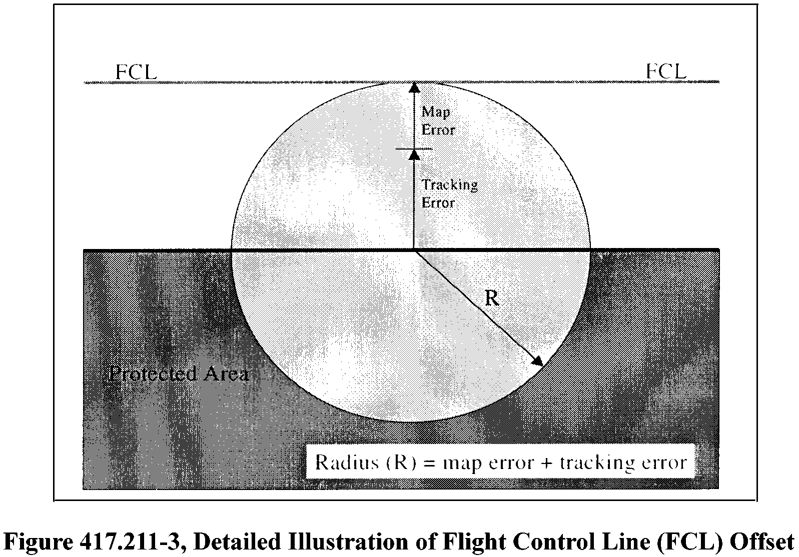 Flight safety limits analysis.
(a) General. A launch operator shall perform a flight safety limits analysis to establish criteria for terminating a malfunctioning launch vehicle's flight. The criteria must ensure that the launch vehicle's debris impact dispersion does not extend beyond the flight control lines established in accordance with § 417.211. A launch operator's flight safety limits analysis must determine the temporal and geometric extents of a launch vehicle's debris impact dispersion on the Earth's surface resulting from any planned debris impacts and potential debris impacts created by unplanned events for any point during flight. At any time during a launch vehicle flight, a launch operator's flight safety limits must provide for the identification of a launch vehicle malfunction and the termination of flight before any adverse effects of the resulting debris could reach outside the flight control lines.
(b) Flight safety limits constraints. A launch operator shall apply the following constraints when establishing flight safety limits:
(1) A launch operator's flight safety limits must account for malfunctions occurring during the time from launch vehicle first motion through flight to the no longer endanger time determined in accordance with § 417.221(c).
(2) A launch operator's flight safety limits shall account for a worst case debris impact dispersion to ensure that the flight safety system is activated in sufficient time to keep the adverse effects of any debris impacts from extending beyond the flight control lines. The worst case dispersion shall be developed by combining dispersion effects in a direction that maximizes the dispersion envelope in the uprange, downrange, right crossrange and left crossrange directions.
(3) A launch operator's flight safety limits must, for a flight termination at any time during launch vehicle flight, represent the extent of the debris impact dispersion, in the uprange, downrange and crossrange directions on the Earth's surface. The surface area bounded by the debris impact dispersion represents the geographic area that will be exposed to the adverse effects of debris impact resulting from flight termination at a given time during flight.
(4) Each debris impact area determined by a launch operator's flight safety limits analysis shall be offset from the flight control lines in a direction away from populated or other protected areas. The size of the offset shall be determined in accordance with paragraph (a) of this section based on impact dispersion parameters that include, but need not be limited to:
(i) Bounce, splatter and skip of inert debris.
(ii) Critical over-pressures greater than or equal to 3.0 psi resulting from detonation of explosive debris.
(iii) Malfunction turns.
(iv) Malfunction imparted velocities.
(v) Winds. Wind data shall be determined in accordance with § 417.217.
(vi) Residual thrust.
(vii) Guidance dispersions.
(viii) Variations in drag predictions of fragments and debris.
(ix) Other impact dispersion parameters peculiar to the launch vehicle.
(x) Debris impact location uncertainties generated from conditions prior to, and after, activation of the flight termination system.
(c) Flight safety limits analysis products. The products of a flight safety limits analysis to be submitted to the FAA in accordance with § 417.203(c) must include the following:
(1) A description of each method used to develop and implement the flight safety limits. The description must include equations and example computations used in the flight safety limits analysis.
(2) A description of how each analysis method meets the analysis requirements and constraints of this section, including how the method produces a worst case scenario for each impact dispersion area.
(3) A description of how the results of the analysis are used in relation to flight control lines to protect populated and other protected areas.
(4) A graphical depiction of the flight safety limits aligned on the nominal flight azimuth, the flight control lines, surrounding landmass areas within 100 nm of the flight control lines, and labeled geodetic latitude and longitude lines from liftoff to orbital insertion or the end of flight. The flight safety limits Start Printed Page 64007shall be shown at trajectory time intervals sufficient to depict the mission success margin between the flight safety limits and the flight control lines. The flight safety limits shall be plotted using the same scales and frequency of plotted points as required for the flight control lines in accordance with § 417.211(e)(1) and (2).
(5) A tabular description of the flight safety limits including the geodetic latitude and longitude for each flight safety limit boundary, the nominal and three-sigma total launch vehicle velocities corresponding to each flight safety limit boundary, the altitude height from the sub-vehicle point to the launch vehicle present position, and the range and bearing from the sub-vehicle point to the vacuum impact point. This data must show the same number of significant digits as the flight control line data submitted in accordance with § 417.211(e)(3).
Straight-up time analysis.(a) General. A launch operator shall perform a straight-up time analysis to determine the latest time-after-liftoff by which flight termination must be initiated were a launch vehicle to malfunction and fly a vertical or near vertical trajectory (a straight-up trajectory) rather than follow a normal trajectory downrange.
(b) Straight-up time constraints. The following constraints apply to straight-up time analysis:
(1) A straight-up trajectory shall be defined as the flight path flown by a launch vehicle that produces vertical or near-vertical flight, beginning at liftoff.
(2) Straight-up time shall be defined as the latest time-after-liftoff, assuming a launch vehicle flies a straight-up trajectory, at which activation of the launch vehicle's flight termination system or spontaneous breakup of the launch vehicle would not cause debris or critical over-pressure to cross over any flight control line established in accordance with § 417.211.
(3) A straight-up-time analysis must account for the following:
(i) Launch vehicle trajectory.
(ii) Drag impact point of each debris fragment.
(iii) Wind effects on the drag impact point of each debris fragment.
(iv) Residual thrust effects on drag impact point of each debris fragment.
(v) Explosion velocity effects on the drag impact point of each debris fragment.
(vi) Malfunction-turn effects on the drag impact point of each debris fragment.
(vii) Distance from the launch point to any flight control line.
(viii) Delay time from the initiation of a flight termination command to actual flight termination.
(ix) Effective casualty area of each debris fragment determined in accordance with § 417.209(c)(9).
(c) Straight-up time analysis products. The products of a straight-up-time analysis to be submitted to the FAA in accordance with § 417.203(c) must include the following:
(1) Straight-up time.
(2) A description of the methodology used to determine straight-up time.
(3) At least one example set of straight-up-time calculations.
Wind analysis.(a) General. A launch operator shall perform a wind analysis to determine wind magnitude and direction as a function of altitude for the air space through which its launch vehicle will fly and for the airspace through which malfunction and jettisoned debris will travel. The products of this analysis must satisfy the input requirements of the other flight safety analyses that are dependent on wind data. A launch operator operating a suborbital launch vehicle flown with a wind weighting safety system shall meet the applicable requirements in this section and the wind analysis requirements of § 417.235(e) and appendix C of this part.
(b) Input. A launch operator's wind analysis must use statistical wind data, measured wind data, or a combination of statistical and measured wind data as input unless otherwise required for a specific vehicle or mission. Wind analysis input data must satisfy the following requirements:
(1) Statistical wind data. Statistical wind input data must include altitude, month, number of observations, mean east-west component of wind speed, standard deviation of east-west component of wind speed, mean north-south component of wind speed, standard deviation of north-south component of wind speed, and the correlation coefficient of wind components. Sources of statistical wind data include, “Information on the Global Gridded Upper Air Statistics (GGUAS),” dated 1980-1995, and Volume 1.1 of the same title, dated March 1996. These documents are available from the Climate Applications Branch, National Climatic Data Center, 151 Patton Ave, Room 468, Asheville, NC 28801-5001.
(2) Measured wind data. Measured wind input data must include altitude, wind magnitude, and wind direction.
(c) Wind analysis constraints. A wind analysis must incorporate the following constraints:
(1) Altitude. A launch operator's wind analysis must provide wind data from the altitude of the launch point to an altitude of 100,000 feet.
(2) Azimuth. For each of the other analyses that are dependent on wind analysis products, a launch operator shall determine wind magnitudes as a function of altitude for the worst-case wind direction (azimuth). This generally requires the determination of wind magnitudes along an azimuth that is in the direction of, and normal to, the nearest protected area such that the wind would carry any hazard toward the protected area. The wind analysis products must demonstrate how each selected azimuth represents the worst-case for its application.
(3) Statistical winds. When using statistical wind input data, a launch operator shall ensure that the wind analysis products represent three-sigma statistical winds assuming a one-sided normal univariate Gaussian distribution. In the absence of inter- and intra-altitude correlation coefficients, a launch operator shall ensure that wind analysis products do not exceed the altitude intervals supplied by the statistical wind input data source. Any temporal combination of statistical wind data must satisfy the following requirements:
(i) Statistical wind data shall be derived from a single data source.
(ii) Any temporal combination of statistical wind data must account for the source's temporal division of samplings, such as weeks, months, or quarters.
(iii) When performing a flight safety analysis with statistical wind data, a launch operator shall use the worst case wind from the statistical wind data source's individual temporal divisions as a function of altitude interval.
(iv) When using statistical wind data that provides height intervals in terms of millibar pressure, a launch operator shall use the mean height for the range of the temporal profile.
(4) Measured and forecasted winds. When using flight-day wind measurements, a launch operator shall forecast wind conditions to account for any changes that may occur between the time the measurements are made and the scheduled flight time and any planned impact time. A launch operator shall forecast wind conditions based on wind measurements taken not more than eight hours before the scheduled liftoff time and any predicted impact time. A launch operator's forecasted wind data must include a scalar wind speed that accounts for the wind measurement error created by the latency of the measured data and any Start Printed Page 64008other error created by the wind measurement methods used. The following requirements apply when using flight-day wind measurements:
(i) Launch area forecasted winds. Using the last measured wind, a launch operator shall forecast the launch area wind speed and wind direction as a function of altitude for the scheduled flight time.
(ii) Downrange area forecasted winds. Using the last measured wind, a launch operator shall forecast for any predicted impact time, the downrange area wind speed and wind direction as a function of altitude in the region of the no-wind three-sigma impact dispersion of each normally jettisoned stage or component.
(5) Wind data for trajectory analysis. A launch operator shall select a wind profile for launch vehicle trajectory development that is as severe as the worst wind conditions under which flight might be attempted. (This wind is not necessarily the wind above which the launch vehicle would lose control or the launch vehicle would fail to maintain structural integrity. Other mission concerns may limit wind conditions.) The following constraints apply to wind analysis performed to determine the wind data needed for the development of the specific launch vehicle trajectories required by § 417.205(d):
(i) Three-sigma maximum performance trajectory and fuel exhaustion trajectory. For this trajectory, a wind analysis must determine the wind magnitude for each trajectory computation point, in the azimuthal direction zero degrees to the projection of the launch vehicle velocity vector azimuth into the horizontal plane that is tangent to the ellipsoidal Earth model at the launch vehicle sub-vehicle point.
(ii) Three-sigma minimum performance trajectory. For this trajectory, a wind analysis must determine the wind magnitude at each trajectory computation point, in the azimuthal direction 180 degrees to the projection of the launch vehicle velocity vector azimuth into the horizontal plane that is tangent to the ellipsoidal Earth model at the launch vehicle sub-vehicle point.
(iii) Three-sigma left lateral trajectory. For this trajectory, a wind analysis must determine the wind magnitude at each trajectory computation point, in the azimuthal direction 90 degrees counter-clockwise to the projection of the launch vehicle velocity vector azimuth into the horizontal plane that is tangent to the ellipsoidal Earth model at the launch vehicle's sub-vehicle point.
(iv) Three-sigma right lateral trajectory. For this trajectory, a wind analysis must determine the wind magnitude at each trajectory computation point, in the azimuthal direction 90 degrees clockwise to the projection of the launch vehicle velocity vector azimuth into the horizontal plane that is tangent to the ellipsoidal Earth model at the launch vehicle's sub-vehicle point.
(6) Flight safety limits. A launch operator shall ensure that the statistical wind percentile used in developing flight safety limits in accordance with § 417.213 is such that when the flight safety limits are used during flight, a normally performing launch vehicle will not trigger flight termination. For example, a launch could not successfully take place at a given location for a given time of year where the statistical winds were such that the resulting launch vehicle debris impact dispersion, determined in accordance with § 417.213, would cross over the flight control lines, developed in accordance with § 417.211, during normal flight.
(7) Flight constraints. When using flight-day wind measurements, a launch operator shall ensure wind dispersion effects based on measured and forecasted wind conditions do not exceed any statistical wind dispersion effects used in developing flight safety limits. A launch operator shall implement launch safety rules, in accordance with § 417.113, that ensure that flight will not be initiated if forecasted winds based on flight-day wind measurements invalidate any wind assumption made when developing flight safety limits.
(d) Wind analysis products. The products of wind analysis to be submitted to the FAA in accordance with § 417.203(c) must include the following:
(1) Statistical wind profiles. A launch operator shall submit a graphic and tabular description of each statistical wind profile used as input for any other flight safety analysis and an explanation of how each profile provides the worst-case wind direction safety margin required by paragraph (c)(2) of this section. A launch operator shall identify each source of its statistical wind data and submit a single graph and table for each statistical percentile and wind direction combination as follows:
(i) Graphic description. A launch operator shall provide a graphical depiction of each statistical wind profile for a given wind direction, showing the wind speed as a function of altitude. This plot must have the vertical axis normal to, and centered on the horizontal axis, with negative wind speeds on the left of the vertical axis and positive wind speeds on the right of the vertical axis. Zero-altitude must be positioned at the intersection of the axes and the altitudes shall be positive in the up direction. The altitude increments must not exceed 1000 feet. Figure 417.217-1 provides an example of a statistical wind profile plot.
Start Printed Page 64009
(ii) Tabular description. A launch operator shall provide a tabular description of each statistical wind profile, including the statistical wind percentile and direction of wind as the title of each table. The altitude and wind speed data must be in columnar format with altitude in column 1 and wind speed to the right side of column 1 in column 2. Altitude shall be in feet, rounded to the nearest foot, and wind speeds shall be in feet per second, rounded to two decimal places. Each altitude increment must not exceed 1000 feet.
(2) Measured wind profile. When using measured wind data, a launch operator shall submit a description of its process for measuring and forecasting winds in the launch area and downrange areas in accordance with paragraph (c)(4) of this section. A launch operator shall provide a tabular description of each measured wind profile in the post launch report required by § 417.117(h). Each table shall include the launch vehicle identification, mission name, date of the measurement, time of the measurement, and the measurement source. The tabular wind data shall include the altitude, wind speed, and wind direction in columnar format, with altitude in column 1, wind speed to the right side of column 1 in column 2 and wind direction to the right of column 2 in column 3. Altitude shall be in feet, rounded to the nearest foot, wind speeds shall be in feet per second, rounded to two decimal places, and wind direction shall be in degrees measured from True North, rounded to one decimal point. Each altitude increment must not exceed 1000 feet.
(3) Flight constraint wind data. A launch operator shall provide the wind magnitude and wind direction information that the launch operator used to develop any wind flight constraints in accordance with paragraph (c)(7) of this section.
(4) Wind data source information. A launch operator shall submit a description of each wind data source, including the type of equipment used to obtain the data, measurement accuracy, and data latency to the flight safety wind analysis process.
No-longer-terminate (gate) analysis.(a) General. A launch operator shall perform an analysis to determine the portion, referred to as a gate, of a flight control line or other flight safety limit boundary, through which a launch Start Printed Page 64010vehicle's tracking icon is allowed to proceed without a launch operator being required to terminate flight. A tracking icon is the representation of a launch vehicle's present position or instantaneous impact point position displayed to a flight safety official at the flight safety official console during real-time tracking of the launch vehicle's flight. A launch operator may use a gate for planned launch vehicle flight over a populated or other protected area only if the launch can be accomplished while meeting the public risk criteria of § 417.107(b).
(b) No-longer-terminate (gate) analysis constraints. The following analysis constraints apply to a gate analysis.
(1) For each gate in a flight safety limit boundary, the criteria used for determining whether to allow passage through the gate or to terminate flight at the gate must use all the same launch vehicle flight status parameters as the criteria used for determining whether to terminate flight at the flight safety limit boundary developed in accordance with § 417.213. For example, if the flight safety limits are a function of instantaneous impact point location, the criteria for determining whether to allow passage through a gate in the flight safety limit boundary must also be a function of instantaneous impact point location. Likewise, if the flight safety limits are a function of drag impact point, the gate criteria must also be a function of drag impact point.
(2) For each established gate, the analysis must account for:
(i) Launch vehicle tracking and map errors.
(ii) Launch vehicle plus and minus three-sigma trajectory limits.
(iii) Debris impact dispersions.
(3) A gate must restrict a launch vehicle's normal trajectory ground trace, within three-sigma of nominal, to a geographic overflight region specifically defined for that gate.
(c) No-longer-terminate (gate) products. The products of a gate analysis to be submitted to the FAA in accordance with § 417.203(c) must include the following:
(1) A launch operator shall describe the methodology used to establish each gate.
(2) A launch operator shall submit a tabular description of the input data.
(3) A launch operator shall submit the analysis computations performed to determine a gate. If a launch involves more than one gate and the same methodology is used to determine each gate, the launch operator need only submit the computations for one of the gates.
(4) A launch operator shall submit a graphic depiction of each gate. A launch operator shall provide a small-scale depiction showing latitude and longitude grid lines, flight control lines, flight safety limits, landmass outlines, and nominal and three-sigma trajectory ground traces in their entirety. A launch operator shall also provide a large-scale depiction showing latitude and longitude grid lines, flight control lines, flight safety limits, landmass overflight regions, applicable portions of the nominal and three-sigma trajectory ground traces, and applicable predicted impact dispersion outlines. A launch operator shall show the gate latitude and longitude labels and the map scale on both depictions. Figures 417.219-1 and 417.219-2 provide examples of the gate depictions for overflight of Africa when launching from Florida.
Start Printed Page 64011
 Data loss flight time analysis.
(a) General. A launch operator shall perform a data loss flight time analysis to determine the shortest elapsed thrusting time during which a launch vehicle can move from its normal trajectory to a condition where public endangerment is possible. A data loss flight time analysis must also determine an earliest destruct time, which is the earliest time after liftoff that public endangerment is possible, and a no longer endanger time, which is the time after liftoff that public endangerment is no longer possible from that time forward. Data loss flight times are used following any malfunction that prevents a flight control officer from knowing the location or behavior of a launch vehicle and that occurs during flight before the no longer endanger time is reached. A launch operator shall incorporate the results of its data loss flight time analysis into its flight termination rules in accordance with § 417.113(c).
(b) Earliest destruct time. A launch operator's earliest destruct time is the earliest possible time after liftoff that the launch vehicle debris impact dispersion could contact a flight control line. When calculating the earliest destruct time, the launch operator shall assume that the launch vehicle loses control immediately after ignition, that vehicle performance and orientation are optimized for maximum debris impact range, and all flight directions are equally likely. In all cases, the earliest destruct time must be greater than the predicted earliest tracking acquisition time plus the time delay determined in accordance with § 417.223.
(c) No longer endanger time. A launch operator's no longer endanger time is the time after liftoff after which flight termination need not be initiated even if a malfunction results in launch vehicle data loss. The no longer endanger time must be the point of orbital insertion or the nominal time after liftoff where, from that time onward, a launch vehicle no longer has the physical ability for its debris impact dispersion to contact a flight control line, whichever comes first.
(d) Data loss flight times. For each launch vehicle trajectory time, from the predicted earliest launch vehicle tracking acquisition time to the no longer endanger time, a launch operator shall determine the data loss flight time in accordance with the following:
(1) A data loss flight time must be the minimum thrusting time for a launch vehicle to move from a normal trajectory position to a position where a flight termination would cause the malfunction debris impact dispersion boundary to contact a flight control line.
(2) A launch operator's data loss flight time analysis must assume a malfunction that causes the launch vehicle to proceed from its position at the malfunction start time toward the flight control line, regardless of the probability of occurrence.
(3) The launch vehicle thrust vector shall be modeled to produce the highest instantaneous impact point range-rate that the vehicle is physically capable of producing at the trajectory time being evaluated, regardless of the probability of occurrence.
(4) Each data loss flight time must account for the system delays at the time of flight.
(5) A launch operator shall determine a data loss flight time for time increments of no less than one second along the launch vehicle nominal trajectory.
(e) Data loss flight times products. The products of a launch operator's data loss flight time analysis to be submitted in accordance with § 417.203(c) must include the following:
(1) A launch operator shall describe the methodology used in its data loss flight times analysis, including identification of all assumptions, Start Printed Page 64012techniques, input data, and equations used. A launch operator shall submit calculations performed for one data loss flight time in the launch area and one data loss flight time in the downrange area. The launch area calculation time shall be separated from the downrange calculation time by at least 50 seconds, or by the greatest time otherwise feasible.
(2) A launch operator shall submit a launch area graphical description that shows flight control lines, flight safety limits, the launch point, the launch site boundaries, the surrounding geographic area, any protected areas, the earliest destruct time, the no longer endanger time (within any applicable scale requirements), latitude and longitude grid lines, and launch vehicle nominal and three-sigma instantaneous impact point ground traces from the launch point to 100 nautical miles downrange. Any launch vehicle trajectory instantaneous impact points must be plotted with sufficient frequency to provide a conformal estimate of the launch vehicle's instantaneous impact point ground trace curvature. A launch operator shall provide labeled latitude and longitude lines and the map scale on the depiction.
(3) A launch operator shall provide a downrange graphical description that shows the flight control lines, flight safety limits, all gates, protected areas, earliest destruct time, no longer endanger time, latitude/longitude grid lines, and any nominal and three-sigma instantaneous impact point ground traces from liftoff through orbital insertion or final stage impact. Any launch vehicle trajectory instantaneous impact points must be plotted with sufficient frequency to provide a conformal estimate of the launch vehicle's instantaneous impact point ground trace curvature. A launch operator shall provide labeled latitude and longitude lines and the map scale on the depiction.
(4) A launch operator shall provide a tabular description of the data loss flight times that includes malfunction start time and the geodetic latitude (positive north of the equator) and longitude (positive east of the Greenwich Meridian) coordinates of the intersection of the launch vehicle instantaneous impact point trajectory with the flight control line. The earliest destruct time and no longer endanger time shall be identified in the table. The tabular description must include data loss flight times for trajectory time increments not to exceed one second.
Time delay analysis.(a) General. A launch operator shall perform a time delay analysis to determine the mean elapsed time between the start of a launch vehicle malfunction and the final commanded flight termination. The time delay must include a flight safety official's decision and reaction time. A launch operator shall also determine the time delay plus and minus three-sigma values relative to the mean time delay.
(b) Time delay analysis constraints. A time delay analysis shall account for data flow rates and reaction times due to hardware and software and decision and reaction times due to personnel that comprise a launch operator's flight safety system as defined by subpart D of this part. A launch operator shall conduct time delay analyses for all data used by a flight safety official for making flight termination decisions. A launch operator's time delay analysis shall account for all significant causes of delay in receiving data. A launch operator's time delay analysis shall account for all delays caused by hardware and software, including, but not limited to, the following:
(1) Tracking system. A launch operator's time delay analysis must account for delays associated with the hardware and software that make up the launch vehicle tracking system, whether or not it is located on the launch vehicle, such as transmitters, receivers, decoders, encoders, modulators, circuitry and any encryption and decryption of data.
(2) Display systems. A launch operator's time delay analysis must account for delays associated with hardware and software that make up any display system used by a flight safety official to aid in making flight control decisions. A launch operator's time delay analysis must also account for any manual operations requirements, tracking source selection, tracking data processing, flight safety limit computations, inherent display delays, meteorological data processing, automated or manual system configuration control, automated or manual process control, automated or manual mission discrete control, and automated or manual failover decision control.
(3) Flight termination system and command control system. A launch operator's time delay analysis must account for delays and response times associated with flight termination system and command control system hardware and software, such as transmitters, decoders, encoders, modulators, relays and shutdown, arming and destruct devices, circuitry and any encryption and decryption of data.
(4) Software specific time delays. A launch operator's time delay analysis must account for delays associated with any correlation of data performed by software, such as timing and sequencing; data filtering delays such as error correction, smoothing, editing, or tracking source selection; data transformation delays; and computation cycle time.
(c) Time delay analysis products. The products of a launch operator's time delay analysis to be submitted in accordance with § 417.203(c) must include the following:
(1) A description of the methodology used to produce the time delay analysis.
(2) A schematic drawing that maps the flight control official's data flow time delays from the start of a launch vehicle malfunction through the final commanded flight termination on the launch vehicle, including the flight safety official's decision and reaction time. The drawings shall indicate major systems, subsystems, major software functions, and data routing.
(3) A tabular listing of each time delay source and its individual mean and plus and minus three-sigma contribution to the overall time delay. All time delay values shall be provided in milliseconds.
(4) The mean delay time and the plus and minus three-sigma values of the delay time relative to the mean value.
Flight hazard areas analysis.(a) General. A launch operator shall perform a flight hazard areas analysis to determine the regions of land, sea, and air (hazard areas) exposed to the potential adverse effects of planned and unplanned launch vehicle flight events and that must be monitored, controlled, or evacuated in order to ensure public safety. The flight hazard area requirements of this section apply to orbital and ballistic launch vehicles that use a flight termination system to protect the public. Flight hazard area requirements that apply to launch of an unguided suborbital rocket that use a wind weighting safety system are contained in § 417.235. A launch operator's flight hazard areas analysis for an orbital launch must satisfy the following:
(1) A launch operator shall use the methodologies for determining hazard areas for orbital launch provided in appendix A of this part. In addition, for both orbital and suborbital launch, a launch operator shall use the methodologies of paragraphs C417.5(f)-(i) of appendix C of this part for determining ship and aircraft hazard Start Printed Page 64013areas for planned debris impacts. A launch operator shall use the methodologies for determining hazard areas provided in appendixes A and C of this part unless the launch operator demonstrates, clearly and convincingly, through the licensing process that another methodology achieves an equivalent level of safety.
(2) A launch operator's analysis must account for all adverse effects and hazards from planned and unplanned launch vehicle flight events, including impacts of inert components, blast effects due to explosive debris impact, projected debris due to debris impact, release of any toxic substance from normal propellant combustion, vehicle breakup or impacting debris, and any other hazard due to planned or unplanned launch vehicle events that may be unique to a launch.
(3) A flight hazard areas analysis must account for debris resulting from planned flight and potential launch vehicle failure determined according to the debris analysis of § 417.209. A launch operator shall determine the debris impact points and dispersions in accordance with the following:
(i) A flight hazard areas analysis must account for drag corrected impact points and dispersions for each class of impacting debris as a function of trajectory time.
(ii) The dispersion for each debris class must account for the position and velocity state vector dispersions at breakup, the delta velocities incurred from breakup produced by either aerodynamic forces or explosive forces from flight termination system activation, the variance produced by winds, variance in ballistic coefficient for each debris class, and any other dispersion variances.
(iii) A launch operator's flight hazard areas analysis may account for the survivability of debris fragments that are subject to reentry aerodynamic forces or heating. A debris class may be eliminated from the analysis if the launch operator performs a survivability analysis and demonstrates that the debris will not survive to impact.
(4) A launch operator's analysis must account for launch vehicle trajectory dispersion effects in the surface impact domain. The analysis must account for trajectory variations, including plus and minus three-sigma variations in the jettison time for each intentionally jettisoned launch vehicle component.
(5) A launch operator's analysis must define the ship and aircraft hazard areas for which Notices to Mariners (NOTMAR) and Notices to Airman (NOTAM) must be issued and the areas where the launch operator must survey in accordance with § 417.121(f). The results of a launch operator's flight hazard areas analyses shall be used to establish launch safety rules in accordance with § 417.113.
(b) Flight hazard area. For each launch, a launch operator shall establish an overall flight hazard area as an area surrounding the launch point that encompasses all hazard areas and safety clear zones established in accordance with paragraphs (d) through (h) of this section. Figure 417.225-1 illustrates a flight hazard area for a coastal launch site. Figure 417.225-2 illustrates a flight hazard area for a land locked launch site. A flight hazard area must account for planned launch vehicle events and potential launch vehicle failures, including any potential commanded flight termination. A flight hazard area must be contained inside the flight control lines established in accordance with § 417.211.
(c) Flight corridor. For regions outside the flight hazard area, a launch operator shall define a flight corridor, which extends downrange from a flight hazard area as illustrated by figure 417.225-3. A flight corridor must be bounded by the flight control lines established in accordance with § 417.211, and must include any land overflight permitted by a gate established in accordance with § 417.219. Any land overflight area must be bounded by a five-sigma cross range trajectory dispersion about the nominal launch vehicle trajectory. A flight corridor must extend for all downrange positions from the flight hazard area to the no longer endanger time determined in accordance with § 417.221(c).
(d) Debris impact hazard area. A launch operator shall determine a debris impact hazard area that accounts for the impact of debris resulting from a commanded flight termination or spontaneous breakup due to a launch vehicle failure and accounts for individual impact locations for each non-inert debris fragment, including explosive or toxic debris. A launch operator shall ensure that a debris hazard area is contained within the flight hazard area and is derived in accordance with the following:
(1) Except as permitted by paragraph (d)(2) of this section, a debris hazard area must be bounded by an individual casualty contour that defines where the individual casualty probability (PC) criteria of 1×10⁻⁶ required by § 417.107(b) would be exceeded if one person were assumed to be in the open and inside the contour during launch vehicle flight. A launch operator shall determine an individual casualty contour in accordance with the following:
(i) The determination of an individual casualty contour must be an iterative process of evaluating person location points in the uprange and downrange directions and both crossrange directions. A launch operator shall use the methodology contained in A417.7 of appendix A of this part unless the launch operator demonstrates, clearly and convincingly, through the licensing process that another methodology achieves an equivalent level of safety.
(ii) For each uprange or downrange distance along the nominal instantaneous impact point trace, individual person location points shall be investigated at progressively increasing crossrange distances until one is found that produces an individual casualty probability of less than the 1×10⁻⁶ criteria.
(iii) As impact points being investigated progress downrange or uprange, the individual casualty contour will come to a close at a point where the individual casualty criteria can no longer be exceeded for any person located further downrange or uprange on the nominal instantaneous impact point trace.
(2) Rather than calculating an individual casualty contour uprange of the launch point as required by paragraph (d)(1) of this section, a launch operator may elect to define the uprange debris impact hazard area as an area surrounding the launch point with a radius equal to the greatest inert debris impact radius and any additional radius due to non-inert debris.
(3) The input for determining a debris impact hazard area must include the results of the trajectory analysis required by § 417.205, the malfunction turn analysis required by § 417.207, the wind analysis required by § 417.217, and the debris analysis required by § 417.209 to define the impact locations of each class of debris established by the debris analysis.
(4) A debris impact hazard area must account for the greatest potential debris impact dispersion. The analysis must assume that the launch vehicle flies until it exceeds a flight safety limit associated with the greatest potential debris impact displacement. The analysis must also assume trajectory conditions that maximize a change in debris impact distance during the flight safety system delay time determined in accordance with § 417.223 and use a debris model that is representative of a flight termination or aerodynamic breakup, whichever results in the greatest debris dispersion. For each launch vehicle breakup event, the analysis must account for trajectory and breakup dispersions, variations in Start Printed Page 64014debris class characteristics, and debris dispersion due to wind.
(5) A debris impact hazard area must account for each impacting debris fragment classified in accordance with § 417.209(c). A debris impact hazard area need not account for debris with a ballistic coefficient of less than three.
(6) The analysis must account for classes of debris and the maximum number of debris fragments within a debris class in accordance with § 417.209(c). Debris classes shall be defined for potential launch vehicle failures that may result in launch vehicle breakup in the flight hazard area.
(7) The analysis must account for the probability of occurrence of each type of launch vehicle failure. The analysis must account for vehicle failure probabilities that vary depending on the time of flight. The analysis must also account for the type of vehicle breakup, either by the flight termination system or by aerodynamic forces that may result in a different probability of existence for each debris class.
(8) The analysis must account for the debris classes produced by a launch vehicle failure or a commanded flight termination and the resulting three-sigma debris impact dispersions. The impact point and the three-sigma debris impact dispersions shall be determined for each debris class at each failure time.
(9) In addition to failure debris, the analysis must account for nominal jettisoned body debris impacts and the corresponding three-sigma debris impact dispersions. The analysis must account for the planned number of debris fragments produced by normal separation events during flight with a probability of occurrence equal to the launch vehicle success rate at the time of each separation event.
(e) Blast overpressure hazard area. A launch operator shall define a blast overpressure hazard area as a circle extending from an explosive debris impact point with a radius equal to the 3.0-psi overpressure distance produced by the equivalent TNT weight of the explosive debris. The analysis must account for the maximum possible total solid and liquid propellant load capability of the launch vehicle and any payload at debris impact. A launch operator shall compute the overpressure radius using the TNT equivalency equation used for quantity distance computations and in accordance with the methodology provided in appendix A of this part. A launch operator shall add the overpressure radius to each explosive debris impact to define the overall blast overpressure hazard area.
(f) Other hazards. A launch operator shall identify any additional hazards, such as radioactive material, that may exist on the launch vehicle or payload that in the form of debris may be an additional hazard to the public. For each such hazard, the launch operator shall identify a hazard area that encompasses any debris impact point and its dispersion and includes an additional hazard radius that accounts for the additional hazard. A launch operator shall account for any hazards due to toxic release and distant focus overpressure blast in accordance with § 417.229 and § 417.231, respectively.
(g) Flight hazard area ship-hit contours. Where applicable, a launch operator shall perform an analysis to define ship hazard areas, referred to as ship-hit contours, to ensure that the probability of hitting a ship satisfies the collective probability threshold of 1×10⁻⁵ required by § 417.107(b). The flight hazard area shall encompass all ship-hit contours. A launch operator shall determine ship-hit contours in accordance with the following:
(1) A launch operator shall determine ship-hit contours for one to 10 ships in increments of one ship. For each given number of ships, the associated ship-hit contour must bound an area around the nominal instantaneous impact point trace where, if the given number of ships were located on the contour, the collective probability of impacting any ship would be less than or equal to the 1×10⁻⁵ ship-hit criteria. A launch operator shall determine each ship hit contour in accordance with the following:
(i) The determination of a ship-hit contour for a given number ships must be an iterative process of evaluating ship location points that have increasing downrange and crossrange distances from the launch point. The total surface area for the given number of ships shall be centered at each ship location point evaluated. A launch operator shall use the methodology for computing ship-hit probability and generating the ship-hit contours contained in A417.5 of appendix A of this part unless the launch operator demonstrates, clearly and convincingly, through the licensing process that another methodology achieves an equivalent level of safety.
(ii) For each downrange distance along the nominal instantaneous impact point trace, ship location points with progressively increasing crossrange distance shall be evaluated until a ship location point is reached that corresponds to a ship-hit probability that is less than or equal to 1×10⁻⁵.
(iii) As the ship location points being evaluated progress downrange, each ship-hit contour will come to a close on the nominal instantaneous impact point trace at a point where the ship-hit criteria can no longer be exceeded for any point further downrange for the number of ships for which the contour is being generated.
(2) The analysis must account for all classes of debris and the number of debris fragments within a debris class as determined in accordance with § 417.209(c). A ship-hit contour need not account for debris with a ballistic coefficient of less than three.
(3) A launch operator shall account for debris classes in accordance with § 417.209(c) for both nominal staging events and potential vehicle failures that may result in vehicle breakup in the flight hazard area. Vehicle failures shall be analyzed as a function of probability of occurrence. As applicable, debris classes shall be produced for both flight termination and for aerodynamic breakup and modeled as a function of probability of occurrence.
(4) Each debris class shall describe the mean impact point and the three-sigma debris impact dispersions. The analysis must account for launch vehicle failure probabilities as a function of flight time. The analysis must also account for the type of vehicle breakup, either by the flight termination system or by aerodynamic forces that may result in a different probability of occurrence for each debris class.
(5) A launch operator shall determine the need to survey the ship-hit contours during the launch vehicle countdown procedures in accordance with A417.5(c) of appendix A. When surveillance is required, a launch operator shall survey for ships in accordance with § 417.121(f). A launch operator shall implement launch safety rules in accordance with § 417.113 where flight shall not be initiated if, at the time of flight, the number of ships within any ship-hit contour is greater than or equal to the number of ships for which the contour was generated.
(6) A launch operator shall use the ship-hit contour for 10 ships as a ship hazard area for providing notice to mariners in accordance with § 417.121(e).
(h) Flight hazard area aircraft-hit contour. A launch operator shall determine an aircraft-hit contour to ensure that the probability of hitting an aircraft satisfies the individual probability threshold of 1×10⁻⁸ required by § 417.107(b) for the flight hazard area around the launch point. A launch operator shall ensure that the aircraft-hit contour is contained within the flight hazard area and is enforced for altitudes extending from zero to 60,000 Start Printed Page 64015feet. A launch operator shall determine an aircraft-hit contour in accordance with the following:
(1) A launch operator shall determine an aircraft-hit contour that bounds an area around the nominal instantaneous impact point trace where, if an aircraft were located on the contour, the individual probability of impacting the aircraft would be less than or equal to the 1×10⁻⁸ aircraft-hit criteria. A launch operator shall determine an aircraft-hit contour following the same method used to determine ship-hit contours required by appendix A of this part.
(2) A launch operator shall use the dimension of the largest aircraft operated in the vicinity of the launch or, if unknown, the dimensions of a Boeing 747 aircraft.
(3) The analysis must account for all classes of debris and the number of debris fragments within a debris class as determined in accordance with § 417.209(c). An aircraft-hit contour need not account for debris with kinetic energy of less than 11 foot pounds.
(4) The analysis must account for debris classes in accordance with § 417.209(c) for both nominal staging events and potential vehicle failures that may result in vehicle breakup in the flight hazard area. Vehicle failures shall be analyzed as a function of probability of occurrence. Debris classes shall be produced for both flight termination and for aerodynamic breakup and modeled as a function of probability of occurrence.
(5) Each debris class must describe the mean impact point and the three-sigma debris impact dispersions. The analysis must account for launch vehicle failure probabilities as a function of flight time. The analysis must also account for the type of vehicle breakup, either by the flight termination system or by aerodynamic forces that may result in a different probability of occurrence for each debris class.
(i) Flight corridor ship hazard areas. Within a flight corridor outside the flight hazard area, a launch operator shall establish a ship hazard area for each planned debris impact for the issuance of notice to mariners in accordance with § 417.121(e). The ship hazard area must consist of an area centered on the planned impact point and defined by the larger of the three-sigma impact dispersion ellipse or an ellipse with the same semi-major and semi-minor axis ratio as the impact dispersion, where, if a ship were located on the boundary of the ellipse, the probability of hitting the ship would be less than or equal to 1×10⁻⁵. A launch operator shall determine ship hazard areas for planned debris impacts using the methodologies contained in paragraphs C417.5(h) and C417.5(i) of appendix C, which apply to both orbital and suborbital launch unless the launch operator demonstrates, clearly and convincingly, through the licensing process that another methodology achieves an equivalent level of safety. A launch operator shall determine if surveillance of a ship hazard area is required in accordance with paragraph C417.5(g) of appendix C of this part.
(j) Flight corridor aircraft hazard areas. Within a flight corridor outside the flight hazard area, a launch operator shall establish aircraft hazard areas for each planned debris impact for the issuance of notices to airmen in accordance with § 417.121(e). Each aircraft hazard area must encompass an air space region, from an altitude of 60,000 feet to impact on the Earth's surface, that contains the larger of the three-sigma drag impact dispersion or an ellipse with the same semi-major and semi-minor axis ratio as the impact dispersion, where, if an aircraft were located on the boundary of the ellipse the probability of hitting the aircraft would be less than or equal to 1×10⁻⁸. A launch operator shall determine aircraft hazard areas for planned debris impacts for both orbital and suborbital launch using the methodology contained in paragraph C417.5(f) of appendix C of this part.
(k) Flight hazard area analysis products. The products of a launch operator's flight hazard area analysis to be submitted in accordance with § 417.203(c) must include, but need not be limited to, the following:
(1) A chart that depicts the flight hazard area, including its size and location.
(2) A chart that depicts each hazard area required by this section.
(3) A description of each hazard for which analysis was performed; the methodology used to compute each hazard area; and the debris classes for aerodynamic breakup of the launch vehicle and for flight termination. For each debris class, the launch operator shall define the number of debris fragments, the variation in ballistic coefficient, and the standard deviation of the debris dispersion.
(4) Charts that depict the ship-hit contours, the individual casualty contour, and the aircraft-hit contour.
(5) Charts and a description of the flight corridor, including any regions of land overflight.
(6) A description of the aircraft hazard area for each planned debris impact inside the flight corridor, the information to be published in a Notice to Airmen, and all information required as part of any agreement with the FAA ATC office having jurisdiction over the airspace through which flight will take place.
(7) A description of any ship hazard area for each planned debris impact inside the flight corridor and all information required in a Notice to Mariners.
(8) A description of the methodology used for determining each hazard area.
(9) A description of the hazard area operational controls and procedures to be implemented for flight.
Start Printed Page 64016
Start Printed Page 64017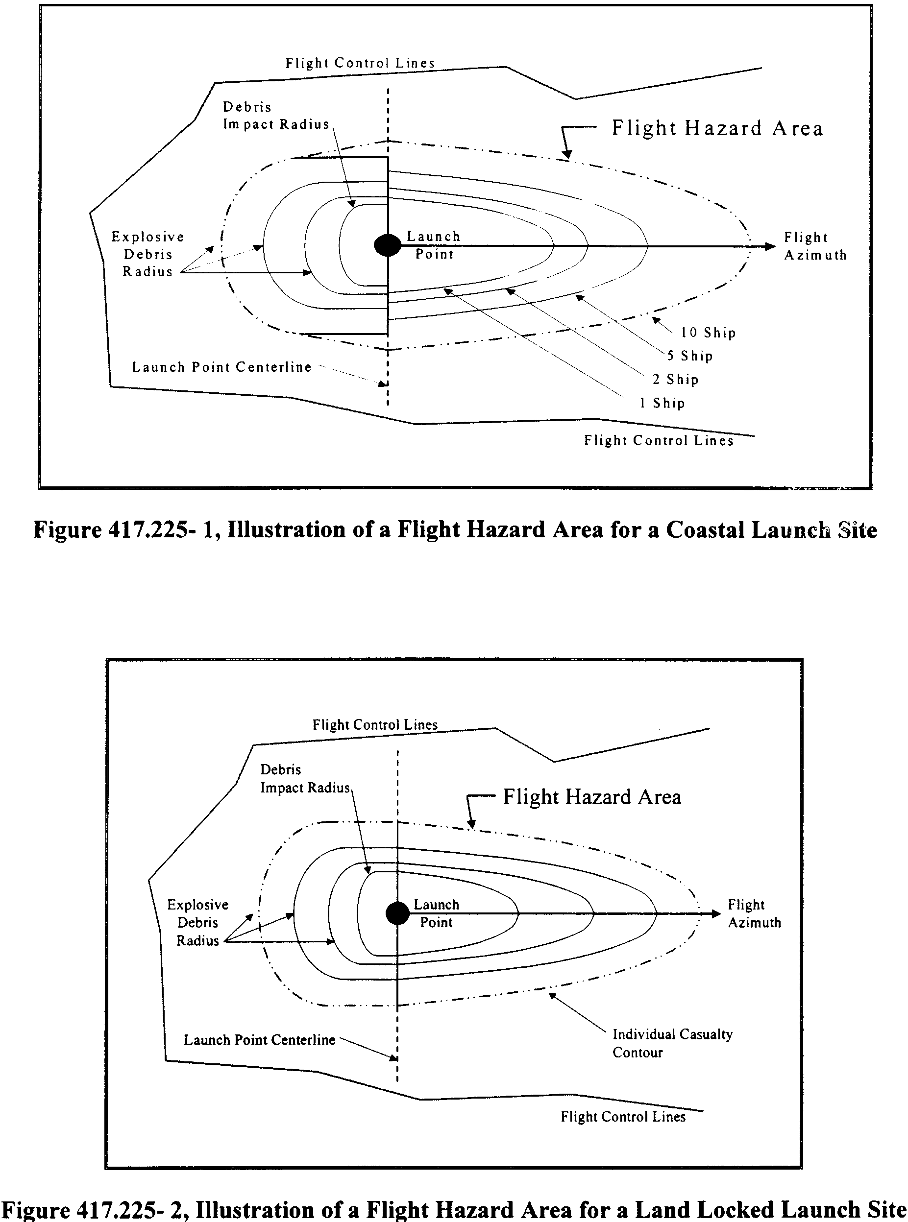
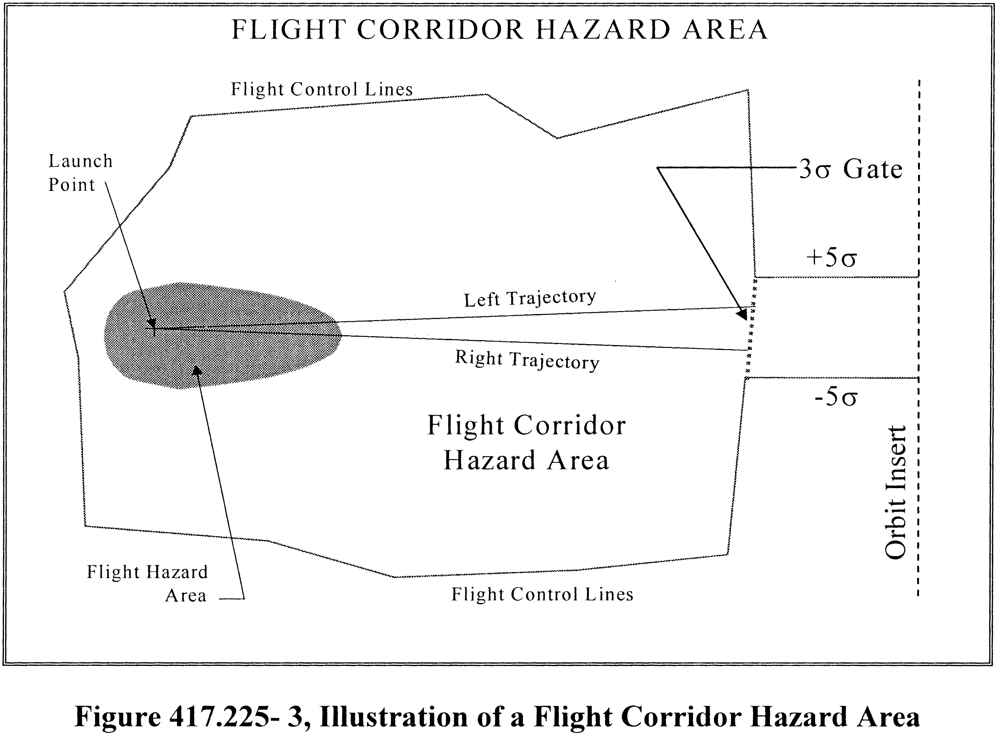 Debris risk analysis.
(a) General. A launch operator shall perform a debris risk analysis to determine the expected average number of casualties (EC) to the collective members of the public exposed to inert and explosive debris hazards from the proposed flight of a launch vehicle. The results of the debris risk analysis must be included in the launch operator's demonstration of compliance with the public risk criteria required by § 417.107 (b). A launch operator's debris risk analysis must include an evaluation of risk to populations on land, including regions of launch vehicle flight following passage through any gate in a flight safety limit boundary established in accordance with § 417.219. The debris risk analysis requirements of this section apply to all launches.
(b) Debris risk analysis constraints. A launch operator's debris risk analysis must be performed in accordance with the following:
(1) A launch operator shall use the methodologies and equations provided in appendix B of this part when performing a debris risk analysis unless, through the licensing process, the launch operator provides a clear and convincing demonstration that an alternate method provides an equivalent level of safety.
(2) A launch operator's debris risk analysis must account for the following populations:
(i) The overflight of populations located outside a flight hazard area and inside any flight control lines established in accordance with § 417.211.
(ii) All populations located within five-sigma left and right crossrange of a nominal trajectory instantaneous impact point ground trace and within five-sigma of each planned nominal debris impact.
(iii) Any planned overflight of the public within any gate overflight areas established in accordance with § 417.219.
(iv) Any populations outside the flight control lines identified in accordance with paragraph (b)(10) of this section.
(3) [Reserved]
(4) A debris risk analysis must account for both inert and explosive debris hazards produced from any impacting debris caused by planned launch vehicle events and breakup of a launch vehicle due to activation of a flight termination system or spontaneous breakup due to a launch vehicle failure during launch vehicle flight. The analysis must account for the debris classes determined by the debris analysis required by § 417.209. A debris risk analysis need not account for debris with a ballistic coefficient of less than three. The analysis must account for all debris hazards as a function of flight time.
(5) A debris risk analysis must account for debris impact points and dispersion for each class of debris in accordance with the following:
(i) A debris risk analysis must account for drag corrected impact points and dispersions for each class of impacting debris resulting from planned flight events and from launch vehicle failure as a function of trajectory time.
(ii) The dispersion for each debris class must account for the position and velocity state vector dispersions at breakup, the delta velocities incurred from breakup produced by either aerodynamic forces or explosive forces from flight termination system activation, the variance produced by winds, variance in ballistic coefficient for each debris class, and any other dispersion variances.
(iii) A launch operator's debris risk analysis may account for the survivability of debris fragments that are subject to reentry aerodynamic forces or heating. A debris class may be eliminated for the debris risk analysis if the launch operator performs a survivability analysis and demonstrates that the debris will not survive to impact.
(6) A debris risk analysis must account for launch vehicle failure probability. For the purposes of a debris risk analysis, a launch operator shall determine the launch vehicle failure probability from theoretical or actual launch vehicle flight data in accordance with the following: Start Printed Page 64018
(i) For a launch vehicle with fewer than 15 flights, a launch operator shall use an overall launch vehicle failure probability of 0.31.
(ii) For a launch vehicle with at least 15 flights, but fewer than 30 flights, a launch operator shall use an overall launch vehicle failure probability of 0.10 or the empirical failure probability, whichever is greater.
(iii) For a launch vehicle with 30 or more flights, a launch operator shall use the empirical failure probability determined from the actual flight history.
(iv) For a launch vehicle with a previously established failure probability that undergoes a modification to a stage, that could affect the reliability of that stage, the launch operator shall apply the previously established failure probability to all unmodified stages and the failure probability requirements of paragraphs (b)(6)(i) through (iii) of this section to the modified stage.
(7) A debris risk analysis must account for the dwell time of the instantaneous impact point ground trace over each populated or protected area being evaluated.
(8) A debris risk analysis must account for the three-sigma instantaneous impact point trajectory variations in left-crossrange, right-crossrange, uprange, and downrange as a function of trajectory time, due to launch vehicle performance variations as determined by the launch operator's trajectory analysis performed in accordance with § 417.205.
(9) A debris risk analysis must account for the effective casualty area as a function of launch vehicle flight time for all impacting debris generated from a catastrophic launch vehicle malfunction event or a planned impact event. A launch operator shall include both payload and vehicle systems and subsystems debris in the effective casualty area. The effective casualty area must account for bounce, skip, and splatter of inert debris, a 3.0-psi blast overpressure radius and projected debris effects for all potentially explosive debris, and a hazard radius for any other non-inert debris. The effective casualty area must account for all debris fragments determined as part of a launch operator's debris analysis in accordance with § 417.209.
(10) A debris risk analysis must account for current population density data obtained from a current population database for the region being evaluated or by estimating the current population using traditional population growth rate equations applied to the most current historical data available. A debris risk analysis must account for the population density of population centers whose grid dimensions on Earth's surface do not exceed 1° latitude by 1° longitude. A debris risk analysis must account for any city with population equal to or greater than 25,000 as an individual population center.
(11) For a launch vehicle that uses a flight termination system, a debris risk analysis must account for the collective risk to any populations outside the flight control lines in the area surrounding the launch site during flight, including people who will be at any public launch viewing area during flight. A launch operator shall use the screening methodology provided in B417.7 of appendix B of this part to identify any populations for which the launch operator shall perform debris risk analysis. For such populations, in addition to the constraints listed in paragraphs (b)(1) through (b)(10) of this section, a launch operator's debris risk analysis must account for the following:
(i) The probability of a launch vehicle failure that would result in debris impact in the areas outside the flight control lines.
(ii) The failure rate of the launch operator's flight safety system. A launch operator may use a flight safety system failure rate of 0.002 if the flight safety system is in compliance with the flight safety system requirements of subpart D of this part. For an alternate flight safety system approved in accordance with § 417.107(a)(3), the launch operator shall demonstrate the validity of the probability of failure on a case-by-case basis through the licensing process.
(iii) Current population density data for the areas being evaluated that are outside the flight control lines. This data shall be determined based on the most current census data and projections for the day and time of flight.
(c) Debris risk analysis products. The products of a launch operator's debris risk analysis to be submitted in accordance with § 417.203(c) must include the following:
(1) A debris risk analysis report that provides the analysis input data, probabilistic risk determination methods, sample computations, and text or graphical charts that characterize the public risk to geographical areas for each launch.
(2) Geographic data showing the launch vehicle nominal, five-sigma left-crossrange and five-sigma right-crossrange instantaneous impact point ground traces; all exclusion zones relative to the instantaneous impact point ground traces; and populated areas included in the debris risk analysis.
(3) A discussion of each launch vehicle failure scenario addressed in the analysis and the probability of occurrence, which may vary with flight time, for each failure scenario. This information must include a failure scenario where a launch vehicle flies within normal limits until some malfunction causes spontaneous breakup or results in a commanded flight termination. For a launch that employs a flight safety system, this information must also describe the most likely launch vehicle failure scenario and probability of occurrence for a random attitude failure as described in B417.7(e) of appendix B of this part.
(4) A population model applicable to the launch overflight regions that contains the following: area identification, location of the center of each population cell by geodetic latitude and longitude, total area, and number of persons in each population cell.
(5) A description of the launch vehicle, including general information concerning the nature and purpose of the launch and an overview of the launch vehicle, including a scaled diagram of the general arrangement and dimensions of the vehicle. A launch operator's debris risk analysis products may reference other documentation submitted to the FAA containing this information. The launch operator shall identify any changes in the launch vehicle description from that submitted during the licensing process according to § 415.109(e). The description must include:
(i) Weights and dimensions of each stage.
(ii) Weights and dimensions of any booster motors attached.
(iii) The types of fuel used in each stage and booster.
(iv) Weights and dimensions of all interstage adapters and skirts.
(v) Payload dimensions, materials, construction, any payload fuel; payload fairing construction, materials, and dimensions; and any non-inert components or materials that add to the effective casualty area of the debris, such as radioactive or toxic materials or high-pressure vessels.
(6) A typical sequence of events showing times of ignition, cutoff, burnout, and jettison of each stage, firing of any ullage rockets, and starting and ending times of coast periods and control modes.
(7) A launch operator shall submit the following information for each launch vehicle motor:
(i) Propellant type and ingredients. Start Printed Page 64019
(ii) Values of thrust.
(iii) Propellant weight and total motor weight versus time.
(iv) A description of each nozzle and steering mechanism.
(v) For solid rocket motors, internal pressure and average propellant thickness, or borehole radius, as a function of time.
(vi) Maximum impact point deviations as a function of failure time during destruct system delays. Burn rate as a function of ambient pressure.
(vii) A discussion of whether a commanded destruct could ignite a non-thrusting motor, and if so, under what conditions.
(8) A launch vehicle's launch and failure history, including a summary of past vehicle performance. For a new vehicle with little or no flight history, a launch operator shall provide summaries of similar vehicles. The data shall include the launches that have occurred; launch date, location, and direction; the number that performed normally; behavior and impact location of each abnormal experience; the time, altitude, and nature of each malfunction; and descriptions of corrective actions taken, including changes in vehicle design, flight termination, and guidance and control hardware and software.
(9) A discussion of the analysis performed for any populations outside the flight control lines in accordance with paragraph (b)(11) of this section.
(10) The value of EC for each populated area evaluated.
Toxic release hazard analysis.For each launch, a launch operator shall perform a toxic release hazard analysis to determine any potential public hazards from any toxic release that will occur during the proposed flight of a launch vehicle or that would occur in the event of a flight mishap. A launch operator shall perform a toxic release hazard analysis using the methodologies contained in appendix I of this part. A launch operator shall use the results of the toxic release hazard analysis to establish for each launch, in accordance with § 417.113(b), flight commit criteria that protect the public from a casualty caused by any potential toxic release. The public includes any members of the public on land and any waterborne vessels and aircraft that are not operated in direct support of the launch.
Distant focus overpressure explosion hazard analysis.(a) General. A launch operator shall perform a distant focus overpressure blast effects hazard analysis to demonstrate that the potential public hazard resulting from impacting explosive debris will not cause windows to break with related injuries. A launch operator shall evaluate potential distant focus overpressure blast effects hazards in accordance with the requirements of this section, which require a launch operator to employ either the deterministic analysis requirements of paragraph (b) of this section or the probabilistic analysis requirements of paragraph (c) of this section.
(b) Deterministic distant focus overpressure hazard analysis. Except as permitted by paragraph (c) of this section, a launch operator shall perform a deterministic distant focus overpressure hazard analysis in accordance with the following:
(1) Explosive yield factors. A launch operator's distant focus overpressure hazard analysis must identify the explosive yield factor curves for each type or class of solid or liquid propellant used by the launch vehicle. For a launch vehicle that uses class 1.3 solid propellant HTPB or PBAN, a launch operator shall perform a distant focus overpressure hazard analysis using the explosive yield factor curves provided in figures 417.231-1 and 417.231-2 unless the launch operator demonstrates, clearly and convincingly, through the licensing process that other explosive yield factor curves apply to the launch and provide for an equivalent level of safety.
(2) Determine the maximum credible explosive yield. A launch operator shall determine the maximum credible explosive yield resulting from the impact of explosive debris resulting from potential launch vehicle failures and flight termination as determined by the debris analysis of § 417.209. The explosive yield shall be determined as a function of impact mass and velocity of impact on the Earth's surface. A launch operator shall determine the explosive yield, expressed as a TNT equivalent, using the explosive yield factor curves determined in accordance with paragraph (b)(1) of this section. This shall be accomplished for impacts of HTPB or PBAN in accordance with the following:
(i) Impacts of intact motors or motor segments on soil. For an intact impact of a HTPB or PBAN solid propellant motor or motor segment, a launch operator shall use the explosive yield factor curves in figure 417.231-1 to determine the explosive yield, expressed as a TNT equivalent. For impact speeds of less than 100 feet per second, the launch operator shall assume the results to be zero. For impact speeds exceeding 800 feet per second, the launch operator shall use the results produced by a speed of 800 feet per second. For a motor or motor segment with a diameter smaller than 40 inches, the launch operator shall use the yield factor for a diameter of 40 inches. For a motor or motor segment with a diameter larger than 146 inches, the launch operator shall use the yield factor for a diameter of 146 inches. For a motor or motor segment with a diameter between 40 and 146 inches, not otherwise specifically represented in Figure 417.231-1, the launch operator shall obtain the yield factor by linear interpolation between the curves represented in Figure 417.231-1.
(ii) Impacts of propellant on soil. For an impact of a HTPB or PBAN solid propellant chunk, a launch operator shall use the explosive yield factor curves in figure 417.231-2 to determine the explosive yield, expressed as a TNT equivalent. For impact speeds less than 100 feet per second, the launch operator shall assume the results to be zero. For impact speeds exceeding 800 feet per second, the launch operator shall use the results produced by a speed of 800 feet per second. For a propellant chunk smaller that 300 pounds, the launch operator shall use the yield factor of a 300-pound propellant chunk. For propellant chunk larger than 60,000 pounds, the launch operator shall use the yield factor of a 60,000-pound propellant chunk. For a propellant chunk between 300 and 60,000 pounds, not otherwise specifically represented in figure 417.231-2, the launch operator shall obtain the yield factor by linear interpolation between the curves represented in figure 417.231-2.
Start Printed Page 64020

(3) Characterize the population exposed to the hazard. A launch operator shall determine if any population centers are vulnerable to a distant focus overpressure hazard using the methodology provided by section 6.3.2.4 of the American National Standard Institute's ANSI S2.20-1983, “Estimating Air Blast Characteristics for Single Point Explosions in Air with a Guide to Evaluation of Atmospheric Propagation and Effects.” The launch operator shall perform these calculations in accordance with the following:
(i) For the purposes of this analysis, a population center is defined as any area outside the launch site and not Start Printed Page 64021under the launch operator's control that contains an exposed site. An exposed site is any structure that may be occupied by human beings, and that has at least one window, excluding automobiles, airplanes, and waterborne vessels. A “single residence,” as used in section 6.3.2.4 of ANSI S2.20-1983 shall be treated as an exposed site. A launch operator shall use the most recent census information on each population center evaluated.
(ii) A launch operator shall determine the distance from the maximum credible impact explosion site to each population center potentially exposed. Unless the launch operator demonstrates, through the licensing process, that the potential explosion site is positively limited to a defined region, the distance between the potential explosion site and a population center must be the minimum distance between any point within the region contained by the flight control lines and the nearest exposed site within the population center.
(iii) A launch operator shall assume that weather conditions are optimized for a distant focus overpressure hazard and use an atmospheric blast focus factor (F) of 5 as defined by ANSI S2.20-1983.
(iv) For the purposes of this analysis, a population center shall be deemed vulnerable to the distant focus overpressure hazard if the “no damage yield limit,” calculated for the population center using the methodology in section 6.3.2.4 of ANSI S2.20-1983, is less than the maximum credible explosive yield. If there are no exposed sites that have a “no damage yield limit” that is less than the maximum credible explosive yield, the launch is exempt from any further requirements in this section.
(4) Estimate the quantity of broken windows. A launch operator shall use a focus factor of 5 and the methods provided by ANSI S2.20-1983 to estimate the number of potential broken windows within each population center determined to be vulnerable to the distant focus overpressure hazard in accordance with paragraph (b)(3) of this section.
(5) Determine and implement measures necessary to prevent distant focus overpressure from breaking windows. For each population center deemed vulnerable to a distant focus overpressure hazard, a launch operator shall determine and implement mitigation measures to protect the public from serious injury from broken windows. This may be accomplished by using one or more of the following measures:
(i) Apply 4-millimeter thick anti-shatter film to windows at all exposed sites.
(ii) Evacuate the exposed public to a location that is not vulnerable to the distant focus overpressure hazard at least two hours prior to the planned flight time.
(iii) If less than 20 windows are predicted to break, as determined in accordance with paragraph (b)(4) of this section, advise the public of the potential for glass breakage.
(iv) Measure the speed of sound as a function of altitude for the time of flight and conduct launches only when an inversion in the sonic velocity profile does not exist within ±30 degrees azimuth toward any population center vulnerable to a distant focus overpressure hazard, accounting for uncertainty in the meteorological conditions present during flight. For a launch operator to use this approach as a mitigation measure, a launch operator shall demonstrate that no window breakage is predicted in any population center due to a maximum credible yield explosion using the analysis methods in section 6.3.2.4.1 of ANSI S2.20-1983. A launch operator may also refine its analysis by performing acoustic ray path calculations to determine the actual focusing region and the focusing factor (F) that apply to a launch as described in section 5.1.3 of ANSI S2.20-1983 using the referenced computer methods.
(c) Probabilistic distance focusing overpressure analysis. When mitigation measures cannot be used a launch operator may apply statistical risk management to control the distant focus overpressure hazard. When proposing to follow this approach, a launch operator shall demonstrate through a distant focus overpressure risk analysis that the launch will be conducted in accordance with the public risk criteria contained in § 417.107(b). The FAA will evaluate any distant focus overpressure risk analysis on a case-by-case basis.
(d) Distant focus over pressure blast effect products. The products of a launch operator's distant focus overpressure analysis to be submitted in accordance with § 417.203(c) must include the following:
(1) A launch operator shall submit a description of the methodology used to produce the distant focus overpressure analysis results, a tabular description of the analysis input data, and a description of any distant focus overpressure mitigation measures implemented. If the launch operator elects to measure the speed of sound as a function of altitude and conduct launches only when a focusing condition toward populated areas does not exist, the launch operator shall submit a description of the method for evaluating weather parameters to determine the existence of conditions that will permit the launch operator to comply with the distant focus overpressure requirements of this section.
(2) A launch operator shall submit one example set of any distant focus overpressure risk analysis computations.
(3) A launch operator shall submit the values for the maximum credible explosive yield as a function of time of flight.
(4) A launch operator shall identify the distance between the potential explosion site and any population center vulnerable to the distant focus overpressure hazard. For each population center, the launch operator shall identify the exposed populations by location and number of people.
(5) A launch operator shall describe any mitigation measures established to protect the public from distant focus overpressure hazards and any flight commit criteria established to ensure the mitigation measures are enforced.
Conjunction on launch assessment.(a) General. A licensee shall obtain a conjunction on launch assessment performed by United States Space Command. A licensee shall implement any launch waits in a planned launch window identified by the conjunction on launch assessment during which flight must not be initiated, in order to maintain a 200-kilometer separation from any inhabitable orbiting object in accordance with § 417.107. A licensee may request a conjunction on launch assessment be performed for other orbital objects to meet mission needs or to accommodate other satellite owners or operators.
(b) Conjunction on launch assessment analysis constraints. A launch operator shall satisfy the following when obtaining and implementing the results of a conjunction on launch assessment:
(1) A licensee shall provide United States Space Command with the launch window and trajectory data needed to perform a conjunction on launch assessment for a launch as required by paragraph (c) of this section, at least 15 days before the first attempt at flight. The FAA will identify a licensee to United States Space Command as part of issuing a license and provide a licensee with current United States Space Command contact information.
(2) A licensee shall obtain a conjunction on launch assessment performed by United States Space Start Printed Page 64022Command 6 hours before the beginning of a launch window.
(3) A conjunction on launch assessment is valid for 12 hours from the time that the state vectors of the inhabitable orbiting objects were determined. If an updated conjunction on launch assessment is needed due to a launch delay, a licensee shall submit the request at least 12 hours prior to the next launch attempt.
(4) For every 90 minutes, or portion of 90 minutes, that pass between the time United States Space Command last determined the state vectors of the orbiting objects, a licensee shall expand each launch window wait by subtracting 15 seconds from the start of the launch window wait and adding 15 seconds to the end of the launch window wait. A launch operator shall incorporate the resulting launch window waits into its flight commit criteria established in accordance with § 417.113.
(c) Information required. A launch operator shall prepare a conjunction on launch assessment worksheet for each launch using a standardized format that contains the input data required by this paragraph. An example conjunction on launch assessment worksheet is provided in figure 417.233-1. A launch operator licensee shall submit the input data to United States Space Command for the purposes of completing a conjunction on launch assessment. A launch operator license applicant shall submit the input data to the FAA as part of the license application process according to § 415.115 of this chapter.
(1) Launch information. A launch operator shall submit the following launch information:
(i) Mission name. A mnemonic given to the launch vehicle/payload combination identifying the launch mission from all others.
(ii) Segment number. A segment is defined as a launch vehicle stage or payload after the thrusting portion of its flight has ended. This includes the jettison or deployment of any stage or payload. A separate worksheet is required for each segment. For each segment, a launch operator shall determine the “vector at injection” as defined by paragraph (c)(5) of this section. Each segment number shall be provided as a sequence number relative to the total number of segments for a launch, such as “1 of 5.”
(iii) Launch window. The launch window opening and closing times in Greenwich Mean Time (referred to as ZULU time on the sample form) and the Julian dates for each scheduled launch attempt.
(2) Point of contact. The person or office within a licensee's organization that collects, analyzes, and distributes conjunction on launch assessment results.
(3) Conjunction on launch assessment analysis results transmission medium. A launch operator shall identify the transmission medium, such as voice, FAX, or e-mail, for receiving results from United States Space Command.
(4) Requestor launch operator needs. A launch operator shall indicate which of the following analysis output formats it requires for establishing flight commit criteria for a launch:
(i) Waits. The times within the overall launch window during which flight must not be initiated.
(ii) Windows. The times within an overall launch window during which flight may be initiated.
(5) Vector at injection. A launch operator shall identify the vector at injection for each segment. The term “vector at injection” is used to identify the position and velocity vectors after the thrust for a segment has ended. The term was originally used to refer to a segment upon orbital injection, but in practice is used to describe any segment of a launch, whether orbital or suborbital.
(i) Epoch. The epoch time, in Greenwich Mean Time (GMT), of the expected launch vehicle liftoff time.
(ii) Position and velocity. The position coordinates in the EFG coordinate system in kilometers and the velocity coordinates in the coordinate system in kilometers per second, of each launch vehicle stage or payload after any burnout, jettison, or deployment.
(6) Time of powered flight. The elapsed time in seconds, from liftoff, for the launch vehicle to arrive at the vector at injection. For each stage or component jettisoned, the time of powered flight shall be measured from liftoff.
(7) Time span for launch window file (LWF). A launch operator shall provide the following information regarding its launch window:
(i) Launch window. The launch window measured in minutes from the initial proposed liftoff time.
(ii) Time of powered flight. The time given in paragraph (c)(6) of this section measured in minutes rounded up to the nearest integer minute.
(iii) Screen duration. The time duration, after all thrusting periods of flight have ended, that a conjunction on launch assessment must screen for potential conjunctions with orbital objects. Screen duration is measured in minutes and must be greater than or equal to 100 minutes for an orbital launch.
(iv) Extra pad. An additional period of time for conjunction on launch assessment screening to ensure the entire first orbit is evaluated. This time shall be 10 minutes unless otherwise specified by United States Space Command.
(v) Total. The summation total of the time spans provided in paragraphs (c)(7)(i) through (c)(7)(iv) of this section expressed in minutes.
(8) Screening. A launch operator shall select spherical or ellipsoidal screening as defined in this paragraph for determining any conjunction. The default shall be the spherical screening method using an avoidance radius of 200 kilometers for habitable orbiting objects. If the launch operator requests screening for any uninhabitable objects, the default shall be the spherical screening method using a miss-distance of 25 kilometers.
(i) Spherical screening. Spherical screening utilizes an impact exclusion sphere centered on each orbiting object's center-of-mass to determine any conjunction. A launch operator shall specify the avoidance radius for habitable objects and for any uninhabitable objects if the launch operator elects to perform the analysis for uninhabitable objects.
(ii) Ellipsoidal screening. Ellipsoidal screening utilizes an impact exclusion ellipsoid of revolution centered on the orbiting object's center-of-mass to determine any conjunction. A launch operator shall provide input in the UVW coordinate system in kilometers. The launch operator shall provide delta-U measured in the radial-track direction, delta-V measured in the in-track direction, and delta-W measured in the cross-track direction.
(9) Orbiting objects to evaluate. A launch operator shall identify the orbiting objects to be included in the analysis.
(10) Deliverable schedule/need dates. A launch operator shall identify the times before flight, “L-times,” that the conjunction on launch assessment is needed.
(d) Conjunction on launch assessment products. A launch operator must submit its conjunction on launch assessment products according to § 417.203(c) and must include the input data required by paragraph (c) of this section. A launch operator licensee shall incorporate the result of the conjunction on launch assessment into its flight commit criteria established in accordance with § 417.113.
Start Printed Page 64023 Analysis for launch of an unguided suborbital rocket flown with a wind weighting safety system.
(a) General. The requirements of this section apply to the launch of an unguided suborbital rocket. A launch operator shall perform a flight safety analysis to determine the launch parameters and conditions under which an unguided suborbital rocket may be flown using a wind weighting safety system. The results of this analysis must demonstrate that any adverse effects resulting from flight will be contained within controlled operational areas and any flight hardware or payload impacts will occur within planned impact areas. The flight safety analysis must Start Printed Page 64024demonstrate compliance with the safety criteria and operational requirements of § 417.125 and must include the other analyses required by this section. The flight safety analysis must be conducted in accordance with appendixes B and C of this part.
(b) Trajectory analysis. A launch operator shall perform a trajectory analysis to determine an unguided suborbital rocket's nominal trajectory and three-sigma dispersed trajectories using the methods provided in appendix C of this part.
(c) Hazard area analysis. A launch operator shall perform a hazard area analysis to determine the land, sea, and air areas that must be monitored, controlled, or evacuated in order to protect the public from the adverse effects of planned unguided suborbital rocket flight events. A flight hazard area, impact hazard area, ship hazard area, and aircraft hazard area must be determined using the methods required by appendix C.
(d) Debris risk analysis. A launch operator shall perform a risk analysis to determine public risk for the expected average number of casualties (EC) due to potential inert and explosive debris impacts resulting from planned or unplanned events occurring during the flight of an unguided suborbital rocket. The analysis shall account for the risk to all populations on land. A debris risk analysis must account for unguided suborbital rocket failure probability, flight dwell times over populated or other protected land areas, five-sigma lateral trajectory dispersion for a normal unguided suborbital rocket, effective casualty area of impacting debris, and population densities. The results of a launch operator's debris risk analysis must demonstrate that the launch will be conducted in accordance with the public risk criteria contained in § 417.107(b). A launch operator shall perform a debris risk analysis for the launch of an unguided suborbital rocket in accordance with § 417.227 and using the methodology provided in appendix B of this part.
(e) Wind weighting analysis. A launch operator shall perform a wind weighting analysis to determine launcher azimuth and elevation settings that correct for the windcocking and wind-drift effects on an unguided suborbital rocket due to wind forces. A launch operator shall perform a wind weighting analysis using the method provided in appendix C of this part and in accordance with the following:
(1) A wind weighting analysis must ensure that three-sigma of all wind weighted stage or other component impacts are contained within a three-sigma performance impact dispersion ellipse about the nominal no-wind impact point, assuming a normal bivariate Gaussian distribution. When determining stage (or impacting body) wind weighted impact points, a launch operator shall account for three standard deviation variations in ballistic performance error parameters, including wind measurement errors and errors in modeled response to wind forces.
(2) A launch operator shall perform an initial wind weighting analysis prior to flight to predict the effects of forecasted or statistical winds on impact point displacement during thrusting phases of flight as well as ballistic free-fall of each unguided suborbital rocket stage until impact.
(3) A launch operator shall perform a final wind weighting analysis as part of the launch-day countdown process with actual measured wind data.
(4) A launch operator shall use the results of a wind weighting analysis and the wind conditions for which the analysis is valid as the basis for flight commit criteria developed in accordance with § 417.113.
(f) Conjunction on launch assessment. A launch operator shall ensure that a conjunction on launch assessment is performed for the flight of an unguided suborbital rocket in accordance with § 417.233.
(g) Products. The products of a launch operator's flight safety analysis for launch of an unguided suborbital rocket to be submitted in accordance with § 417.203(c) must include the trajectory analysis products, hazard area analysis products, and wind weighting analysis products required by appendix C of this part. A launch operator shall also submit debris risk analysis products in accordance with § 417.227 and conjunction on launch assessment products in accordance with § 417.233.
[Reserved]Subpart D—Flight Safety System
General.(a) A launch operator shall use a flight safety system that provides a means of preventing a launch vehicle and its hazards, including any payload hazards, from reaching the public in the event of a launch vehicle failure during flight. Requirements that define when a launch operator must employ a flight safety system are provided in § 417.107(a).
(b) A flight safety system must consist of a flight termination system, a command control system, and the support systems defined in this subpart, including all associated hardware and software unless the requirements of § 417.107(a)(3) apply. A flight safety system also includes the functions of any personnel who operate flight safety system hardware and software. A launch operator shall satisfy each requirement of this subpart, including all requirements contained in referenced appendices, by meeting the requirements or by using an alternate method approved by the FAA through the licensing process. If a flight safety system does not satisfy all the requirements of this subpart, the requirements of § 417.107(a)(3) apply. The FAA will approve an alternate method if a launch operator provides a clear and convincing demonstration that its proposed method provides an equivalent level of safety to that required by this subpart. A launch operator shall obtain FAA approval of any proposed alternate method before its license application or application for license modification will be found sufficiently complete to initiate review pursuant to § 413.11 of this chapter.
(c) A launch operator's test program, required by § 417.115, must demonstrate the ability of a flight safety system to meet the design margins and reliability requirements of this subpart and the ability of the flight safety system to function without degradation in performance when subjected to non-operating and operating environments. The test program must satisfy the requirements of § 417.115 and include tests of the flight termination system and command control system as required by § § 417.315, 417.317 and 417.325. The test program must include tests of the support systems required by § 417.327 and the equipment and instrumentation associated with the flight safety system, including real-time computers, display systems, consoles, telemetry, command control, tracking systems, and video systems. The cause of any test failure must be determined, corrective actions implemented, and additional testing performed to demonstrate that the test criteria are satisfied before flight.
(d) Any change to a licensee's flight safety system design or flight safety system test program that was not coordinated during the licensing process must be submitted to the FAA for approval as a license modification prior to flight.
(e) Prior to the flight of each launch vehicle, a licensee shall confirm to the FAA in writing that its flight safety system is as described in its license application, including all applicable application amendments and license modifications, and complies with all terms of the license and the requirements of this part. Start Printed Page 64025
(f) Upon review of a proposed launch, the FAA may identify and impose additional requirements needed to address unique issues presented by a flight safety system, including its design, operational environments, and testing.
Launch vehicle flight termination system functional requirements.(a) A launch operator shall use a flight termination system as part of a flight safety system. A flight termination system consists of all hardware and software onboard a launch vehicle needed to accomplish all flight termination functions in accordance with this section.
(b) Once initiated, a flight termination system must render each stage and any other propulsion system, including any propulsion system that is part of a payload that has the capability of reaching a populated or other protected area, non-propulsive, without significant lateral or longitudinal deviation in the impact point. A flight termination system must terminate flight in each thrusting stage and propulsion system. Any stage or propulsion system not thrusting at the time the flight termination system is initiated must be rendered incapable of becoming propulsive.
(c) The flight termination of one stage must not sever interconnecting flight termination system circuitry or ordnance of another stage until the flight termination of the other stage has been initiated.
(d) A flight termination system must destroy the pressure integrity of all solid propellant stages and strap-on motors. A flight termination system must terminate all thrust, or any residual thrust must cause a solid propellant stage or strap-on motor to tumble without significant lateral or longitudinal deviation in the impact point.
(e) A flight termination system must cause dispersion of any liquid propellant, whether by rupturing the propellant tank or other equivalent method, and initiate burning of any toxic liquid propellant.
(f) A flight termination system must not detonate any solid or liquid propellant.
(g) A flight termination system must include a command destruct system that is initiated by radio command and implemented in accordance with § 417.309. The FAA will approve another method, such as an autonomous flight termination system, if a launch operator provides a clear and convincing demonstration, through the licensing process, that its proposed method provides an equivalent level of safety.
(h) A flight termination system must provide for flight termination of any inadvertently or prematurely separated stage or strap-on motor capable of reaching a populated or other protected area before orbital insertion. Each stage or strap-on motor that does not possess its own complete command destruct system in accordance with § 417.309 must be equipped with an inadvertent separation destruct system that complies with the requirements of § 417.311.
Flight termination system reliability.(a) Reliability design. A flight termination system must have a reliability design of 0.999 at a confidence level of 95 percent. A launch operator shall conduct system reliability analyses according to § 417.329 to demonstrate whether a flight termination system has the required reliability design.
(b) Single fault tolerant. A flight termination system, including monitoring and checkout circuits, must not have a single failure point that would inhibit functioning of the system or produce an inadvertent output. Exceptions to this requirement apply to certain components that are identified in this subpart and that meet the design and test requirements in appendixes D and E of this part.
(c) Redundancy. A flight termination system must utilize redundant component strings in accordance with the following:
(1) Redundant components shall be structurally, electrically, and mechanically separated and mounted in different orientations on different axes.
(2) A flight termination system need not use redundant linear shaped charges, if, when employing a single linear shaped charge, the charge initiates at both ends, and the initiation source for one end is independent of the initiation source used for the other end.
(3) Passive components such as antennas and radio frequency couplers are not required to be physically redundant if they satisfy the requirements of appendix D of this part.
(d) System independence. A flight termination system must not share any power sources, cabling, or any other component with any other launch vehicle system. With the exception of any telemetry monitor signal and any engine shut-down output signal, a flight termination system must operate independently of all other vehicle systems.
(e) Components and parts. A licensee is responsible for the overall design of a flight termination system and shall ensure that all flight termination system components satisfy the requirements of appendix D of this part and all electronic piece parts used in a flight termination system component satisfy the requirements of appendix F of this part. A launch operator shall ensure that each flight termination system component and electronic piece part has written performance specifications that contain the particulars of how the component or piece part satisfies the requirements of appendixes D and F as related to the specific design of the flight termination system that contains the component or piece part.
(f) Testability. The design of a flight termination system and associated ground support and monitoring equipment shall provide for preflight testing performed in accordance with § 417.317.
(g) Software and firmware. A launch operator shall ensure that each software safety critical function associated with a flight termination system is identified, and that all associated computing systems, software, or firmware is designed, compiled, analyzed, tested, and implemented in accordance with § 417.123 and appendix H of this part. The requirements of appendix H also apply to any computing system, software, or firmware that must operate properly to ensure that the flight safety official has the accurate vehicle performance data needed to make a flight termination decision.
(h) Component storage, operating, and service life. All flight termination system components must have a specified storage life, operating life, and service life. Service life is the total time that a component spends in storage and after installation on the launch vehicle through the end of flight. The storage or service life of a component must start upon completion of the component's acceptance testing. Operating life must start upon activation of the component or installation of the component on a launch vehicle, whichever is earlier. A flight termination system component must function without degradation in performance when subjected to the full length of its specified storage life, operating life, and service life. A launch operator shall ensure that each component used in a flight termination system does not exceed its storage, operating, or service life before flight. A launch operator shall ensure that age surveillance testing, in accordance with appendix E of this part, is performed to verify or extend a component's storage, operating, or service life.
Start Printed Page 64026Flight termination system environment survivability.(a) General. The design of a flight termination system and its components, including all mounting hardware, cables and wires, must provide for the system and each component to function without degradation in performance when subjected to dynamic environment levels greater than those that it will experience during environmental stress screening tests, ground transportation, storage, launch processing, system checkout, and flight up to the point that the launch vehicle could no longer impact any populated or other protected area, or when subjected to dynamic environment levels greater than those that would cause structural breakup of the launch vehicle.
(b) Maximum predicted environments. A launch operator shall determine, based on analysis, modeling, testing, or flight data, all maximum predicted environments for the non-operating and operating environments that a flight termination system is to experience. The non-operating and operating environments must include, but need not be limited to, thermal range, vibration, shock, acceleration, acoustic, and other environments where applicable to a launch, such as humidity, salt fog, dust, fungus, explosive atmosphere, and electromagnetic energy. The specific environments that apply to the design of flight termination system components are identified in appendix D of this part. A launch operator shall determine each maximum predicted environment in accordance with the following:
(1) If there are fewer than three samples of flight data, a launch operator shall add no less than a 3 dB margin for vibration, 4.5 dB for shock, and plus and minus 11°C for thermal range to each maximum predicted environment identified through analysis.
(2) For a new launch vehicle or for a launch vehicle for which there is no empirical data available or empirical data for fewer than three flights, a launch operator shall monitor launch vehicle flight environments with telemetry to verify each maximum predicted environment. A launch operator shall ensure that each maximum predicted environment for any future launch is adjusted to reflect the flight data obtained through monitoring. A launch operator's post-launch report, submitted in accordance with § 417.117(h), must contain the results of any flight environment monitoring performed to verify the maximum predicted environments.
(3) A launch operator shall monitor each transportation, storage, launch processing, and system checkout environment, and adjust the associated maximum predicted environments to reflect the true environments.
(4) The launch operator shall notify the FAA of any change to any maximum predicted environment.
Command destruct system.(a) A flight termination system must include a command destruct system that is initiated by radio command and meets the redundancy and other component requirements provided in appendix D of this part. Redundant radio command receiver decoders must be installed on or above the last propulsive launch vehicle stage or payload capable of reaching a populated or other protected area before orbital insertion.
(b) The initiation of a command destruct system must result in accomplishing all flight termination system functions in accordance with § 417.303.
(c) A command destruct system must operate with a radio frequency input signal that has an electromagnetic field intensity of 12 dB below the intensity provided by a command control system transmitter over 95 percent of the radiation sphere surrounding a launch vehicle at any point along the launch vehicle's trajectory.
(d) The design of a command destruct system must provide for the command destruct system to survive the breakup of the launch vehicle to the point that all flight termination functions would be accomplished in accordance with § 417.303. Otherwise, the stage containing the command destruct system must also include an inadvertent separation destruct system implemented in accordance with § 417.311. A launch operator shall perform a breakup analysis in accordance with § 417.329 to demonstrate the survivability of a command destruct system.
(e) A command destruct system must receive and process a valid arm command before accepting a destruct command and destroying the launch vehicle. For any liquid propellant, a command destruct system must non-destructively shut down any thrusting liquid engine as a prerequisite for destroying the launch vehicle.
Inadvertent separation destruct system.(a) Each stage or strap-on motor capable of reaching a populated or other protected area before orbital insertion, and which does not possess its own complete command destruct system, including command destruct receivers and associated radio frequency hardware, must be equipped with an inadvertent separation destruct system. An inadvertent separation destruct system is an automatic destruct system that uses mechanical means to trigger the destruction of a stage. If a command destruct system on a stage does not satisfy the requirement of § 417.309(d) that the command destruct system survive breakup of the launch vehicle, a launch operator must also use an inadvertent separation destruct system on that stage.
(b) The initiation of an inadvertent separation destruct system must result in accomplishing all flight termination system functions required by § 417.303 and that apply to the stage or strap-on motor on which it is installed.
(c) An inadvertent separation destruct system must be activated by a device that senses launch vehicle breakup or premature separation of the stage or strap-on motor on which it is located.
(d) An inadvertent separation destruct system must be located to survive during launch vehicle breakup and to ensure its own activation. A launch operator shall perform a flight termination system survivability analysis that accounts for breakup of the launch vehicle and the timing of planned launch vehicle staging events. The analysis shall be used to determine the method of activation and location of an inadvertent separation destruct system that will ensure its survivability and activation during breakup of the launch vehicle.
(e) An electrically initiated inadvertent separation destruct system must have a dedicated power source that supplies the energy to initiate the destruct ordnance.
Flight termination system safing and arming.(a) General. The design of a flight termination system must provide for safing and arming of all flight termination system ordnance through the use of ordnance initiation devices or arming devices, also referred to as safe and arm devices, that provide a removable and replaceable mechanical barrier or other positive means of interrupting power to each of the ordnance firing circuits to prevent inadvertent initiation of ordnance.
(b) Flight termination system arming. The design of a flight termination system must provide for each flight termination system ordnance initiation device or arming device to be armed prior to arming any launch vehicle or payload propulsion ignition circuits. For a launch where propulsive ignition Start Printed Page 64027occurs after first motion of the launch vehicle, the design of a flight termination system must provide an ignition interlock that prevents the arming of any launch vehicle or payload propulsion ignition circuits unless all flight termination system ordnance initiation devices and arming devices are armed.
(c) Preflight safing. The design of a flight termination system must provide for remote and redundant safing of all flight termination system ordnance initiation devices and arming devices before launch and in case of launch abort or recycle operations.
(d) In-flight safing. If flight termination system ordnance is to be safed after a stage or strap-on motor is spent, attains orbit, or can no longer reach any populated or other protected area, the flight termination system safing design must provide for the following:
(1) Any onboard launch vehicle hardware or software used to automatically safe flight termination system ordnance must be single fault tolerant against inadvertent safing. An automatic safing design must satisfy the following:
(i) Any automatic safing must depend on at least two independent parameters, such as time of flight or altitude. The safing criteria for each independent parameter must ensure that the flight termination system on a stage or strap-on-motor can only be safed once the stage or strap-on motor attains orbit or can no longer reach a populated or other protected area.
(ii) An automatic safing design must ensure that all flight termination system ordnance initiation devices and arming devices remain armed during flight until the safing criteria for at least two independent parameters are met.
(iii) If a launch operator proposes to establish any single safing criterion as a value that may be achieved before normal thrust termination of the associated stage or strap-on motor, a launch operator shall demonstrate to the FAA, through the licensing process, that the greatest remaining thrust, assuming a three-sigma high engine performance, can not result in the stage or strap-on motor reaching a populated or other protected area.
(2) If a command destruct system is to be safed by radio command, the command control system used for in-flight safing must be single fault tolerant against inadvertent safing. A launch operator shall implement operational procedures to ensure that launch support personnel do not safe a flight termination system by radio command until the launch vehicle attains orbit or can no longer reach any populated or other protected area.
(e) Safe and arm monitoring. The design of a flight termination system must provide for remote monitoring of the safe and arm status of each flight termination system ordnance initiation device and arming device. Safe and arm monitoring circuits must comply with appendix D of this part.
Flight termination system testing.(a) General. A launch operator shall use flight termination system components that satisfy the qualification, acceptance, and age surveillance test requirements provided in appendix E of this part and any other test requirements established during the licensing process. In addition, a flight termination system and its components shall be subjected to preflight tests in accordance with § 417.317.
(b) Test plans. For each launch, a launch operator shall implement written test plans and procedures that specify the test parameters, including pass/fail criteria, for each test and the testing sequence required by appendix E of this part for the applicable component. A launch operator shall also implement test plans for the preflight tests required by § 417.317. Upon review of a proposed launch, the FAA may identify and require additional testing needed to address any unique flight termination system design or operational environment.
(c) Performance variation. All performance parameters measured during component testing shall be documented for comparison to previous and subsequent tests to identify any performance variations that may indicate potential workmanship or defects that could lead to a failure of the component during flight.
(d) Testing of piece parts. All electronic piece parts used in a flight termination system or a flight termination system component must be tested in accordance with appendix F of this part.
(e) Visual inspection. Visual inspections for workmanship and physical damage must be performed before and after each test.
(f) Test reports. A launch operator shall prepare test reports for each launch. A test report must document all flight termination system test results and test conditions. Also, any analysis performed in lieu of testing shall be documented in a test report. The test results must be traceable to each applicable system and component using serial numbers or other identification. A test report must include any data that represents “family characteristics” to be used for comparison to subsequent tests of components and systems. Any test failure or anomaly, including any variation from an established performance baseline, must be documented with a description of the failure or anomaly, each corrective action taken, and all results of additional tests. Each test report must include a signed statement by each person performing the test and any analysis, attesting to the accuracy and validity of the results.
(1) Qualification test reports. A launch operator shall submit all qualification test reports to the FAA no later than six months prior to the first flight attempt. For subsequent launches of the same launch vehicle, a launch operator shall submit qualification test reports for any changes to the flight termination system.
(2) Acceptance, age surveillance, and preflight test reports. A launch operator shall submit a summary of each acceptance and age surveillance test no later than 30 days prior to the first flight attempt for each launch. The summary must identify when and where the tests were performed and provide the results. Complete acceptance, age surveillance, and preflight test reports shall be made available to the FAA upon request. A launch operator shall immediately report any failure of a preflight test to the FAA. The resolution of a preflight test failure must be approved by the FAA through the licensing process prior to flight.
(g) Redesign and retest. In the case of a redesign of a component due to a failure during testing, all previous tests applicable to the redesign shall be repeated unless the launch operator demonstrates that other testing achieves an equivalent level of safety.
(h) Configuration management and control. A launch operator shall ensure that a flight termination system component's manufactured parts, materials, processes, quality controls, and procedures are standardized and maintained in accordance with the launch operator's configuration management and control plan submitted during the licensing process according to § 415.119(e) of this chapter. A launch operator shall ensure that subsequent production items are identical to the components subjected to qualification testing. If there is a change in the design of a qualified component, including any change in a component's parts, the component must be re-qualified in accordance with appendix E of this part.
Start Printed Page 64028Flight termination system preflight testing.(a) General. A launch operator shall conduct preflight flight termination system testing at the component level and the system level in accordance with this section and the applicable requirements provided in § 417.315.
(b) Preflight component tests. Preflight component tests shall be conducted at the launch site after qualification and acceptance testing to detect any change in performance that may have resulted from shipping, storage, or other environments that may have affected performance. Performance parameter measurements shall be made during preflight component tests and compared to the acceptance test performance baseline to identify any performance variations, including out-of-family data, which may indicate potential defects that could result in an in-flight failure. Preflight component tests shall be conducted in accordance with this section.
(c) Batteries. Each flight termination system battery shall be tested as follows:
(1) The preflight activation and testing of a flight termination system battery prior to installation on a launch vehicle shall include:
(i) Any acceptance testing not previously completed.
(ii) Open circuit testing of each flight termination system battery and each battery cell.
(iii) Load testing of each completed battery assembly.
(iv) Testing of continuity and isolation of each connector.
(v) For manually activated batteries, the pin to case voltage shall be tested to ensure no electrolyte spillage during activation.
(2) A launch operator shall ensure that the time interval between preflight activation and testing of a battery and flight does not exceed the battery's operating life stand time capability.
(3) Battery activation processes and procedures shall be identical to those used during qualification testing.
(4) The preflight testing of a nickel cadmium battery prior to installation shall satisfy the following requirements and in the following order:
(i) The battery shall be initially charged at a rate equal to the battery amp hour capacity divided by 20 (C/20 rate) for 2 hours and then further charged at a C/10 rate for 15 hours.
(ii) The battery shall then be discharged at a C/2 rate to 0.9 volts per cell battery voltage, then discharged at C/10 rate until the first cell reaches 0.1 volts.
(iii) The battery shall then be discharged across a resistor with resistance in ohms equal to the number of cells in the battery times 10 divided by the battery amp hour capacity until the first battery cell reaches 0.05 volts.
(iv) The battery shall then be recharged at 20 ±5 °C and at a C/10 rate for 16 hours.
(v) The battery shall then be subjected to 20 °C capacity and overcharge testing for 3 cycles.
(vi) The battery shall then be subjected to capacity retention and final impedance and pulse voltage determination at 20 °C and then discharged at −10 °C for 1 cycle.
(d) Preflight testing of a safe and arm device that has an internal electro-explosive device. An internal electro-explosive device in a safe and arm device shall undergo preflight testing in accordance with the following:
(1) Preflight testing shall be performed no earlier than 10 calendar days before flight.
(2) Preflight testing must include visual checks for signs of physical defects.
(3) Preflight testing must include safing and arming each device and performing continuity and resistance checks of the electro-explosive device circuit in both the arm and safe position.
(e) Preflight testing for an external electro-explosive device. An external electro-explosive device in a safe and arm device shall undergo preflight testing in accordance with the following:
(1) Preflight testing shall be performed no earlier than 10 calendar days before flight.
(2) Preflight testing must include visual checks for signs of physical defects and resistance checks of the electro-explosive device.
(f) Preflight testing for an exploding bridgewire firing unit. An exploding bridgewire firing unit must undergo preflight testing in accordance with the following:
(1) Preflight testing shall be performed no earlier than 10 calendar days before flight.
(2) Preflight testing must include verification of bridgewire continuity.
(3) Where applicable, preflight testing shall include high voltage static and dynamic gap breakdown voltage tests.
(g) Preflight testing for command destruct receivers and other electronic components. Electronic components shall include any flight termination system component that contains piece part circuitry such as a command destruct receiver. A launch operator shall conduct preflight testing of a command destruct receiver or other electronic component in accordance with the following:
(1) Preflight testing shall be accomplished no earlier than 180 calendar days prior to flight. If the 180-day period expires before flight, an installed electronic component must either be replaced by one that meets the 180-day requirement or tested in place in accordance with an alternate preflight test plan that must be approved by the FAA, through the licensing process, prior to its implementation.
(2) Preflight testing must measure all performance parameters at ambient temperature. The test procedures must satisfy the requirements of appendix E of this part.
(3) Acceptance tests may be substituted for the preflight tests if the acceptance tests are performed no earlier than 180 calendar days prior to flight.
(h) Preflight subsystem and system level tests. A launch operator shall conduct preflight subsystem and system level tests of the flight termination system after its components are installed on a launch vehicle to ensure proper operation of the final subsystem and system configurations. Data obtained from these tests shall be compared for consistency to the preflight component tests and acceptance test data to ensure there are no discrepancies indicating a flight reliability concern. Preflight subsystem and system level tests shall be in accordance with the following:
(1) Antennas and associated radio frequency systems shall be tested once installed in their final flight configuration to verify that the voltage standing wave ratio and any insertion losses are within the design limits.
(2) A launch operator shall perform a system level radio frequency preflight test from each command control system transmitter antenna used for the first stage of flight to each command receiver no earlier than 90 days before flight to validate the final integrity of the radio frequency system. These tests shall include calibration of the automatic gain control signal strength curves, verification of threshold sensitivity for each command, and verification of operational bandwidth.
(3) A launch operator shall perform end-to-end tests on all flight termination system subsystems, including command destruct systems and inadvertent separation destruct systems. End-to-end tests shall be performed no earlier than 72 hours before the first flight attempt. If the flight is delayed more than 14 calendar days or the flight termination system configuration is broken or modified for any reason, such as to Start Printed Page 64029replace batteries, the end-to-end tests shall be repeated no earlier than 72 hours before the next flight attempt. A launch operator shall perform end-to-end tests with the flight termination system in its final onboard launch vehicle configuration except for the ordnance initiation devices. End-to-end tests must incorporate the following:
(i) A destruct initiator simulator that satisfies § 417.327 shall be installed in place of each flight initiator to verify that the command destruct and inadvertent separation destruct systems deliver the energy required to initiate flight termination system ordnance.
(ii) All flight termination systems shall be powered by the batteries that will be used for flight. A flight termination system battery shall not be recharged at any time during or after end-to-end testing. If the battery is recharged at any time before flight the entire end-to-end test shall be performed again.
(iii) All command destruct receiver commands shall be exercised using the command control system transmitters in their flight configuration.
(iv) All primary and redundant flight termination system components, circuits and command control system transmitting equipment shall be verified as operational.
(v) The triggering mechanism of all electrically initiated inadvertent separation destruct systems shall be exercised and verified as operational.
(4) An open-loop radio frequency test shall be performed, no earlier than 60 minutes prior to flight, to validate the entire radio frequency command destruct link. This test shall be performed in accordance with the following:
(i) All flight termination system ordnance initiation devices must be in a safe condition.
(ii) Flight batteries must power all receiver decoders and other electronic components. The launch operator shall ensure that the testing allows for any warm-up time needed to ensure the reliable operation of electronic components.
(iii) All receiver decoder commands except destruct shall be exercised open loop from the command control transmitters.
(iv) All receiver decoders and all command control transmitters shall be tested and verified as operational.
(5) If the integrity of a subsystem or system is compromised due to a configuration change or other event, such as a lightning strike or inadvertent connector mate or de-mate, the associated preflight subsystem or system testing shall be repeated.
Flight termination system installation procedures.(a) A launch operator shall implement written procedures to ensure that flight termination system components, including electrical components and ordnance, are installed on a launch vehicle in accordance with the flight termination system design. These procedures must ensure that:
(1) All personnel involved are qualified for the task in accordance with § 417.105.
(2) The installation of all flight termination system mechanical interfaces is complete.
(3) Qualified personnel use calibrated tools to install ordnance when a specific standoff distance is necessary to ensure that the ordnance has the desired effect on the material it is designed to cut or otherwise destroy.
(b) Flight termination system installation procedures must include, but need not be limited to the following:
(1) A description of each task to be performed, each facility to be used, and each and any hazard involved.
(2) A checklist of tools and equipment required.
(3) A list of personnel required for performing each task.
(4) Step-by-step directions written with sufficient detail for a qualified person to perform each task. The directions must identify any tolerances that must be met during the installation.
(5) Steps for inspection of installed flight termination system components, including quality assurance oversight procedures.
(6) A place for the personnel performing the procedure to initial or otherwise signify that each step is accomplished and for recording the outcome and any data verifying successful installation.
Flight termination system monitoring.(a) A launch operator shall ensure that the following data is available through monitoring to determine the status of a flight termination system prior to and during flight:
(1) The signal strength telemetry output voltage for the command destruct receiver.
(2) All command destruct receiver outputs commands.
(3) Status of each ordnance initiation device, whether in the arm or safe position.
(4) Voltage monitoring for each flight termination system battery.
(5) Current monitoring for each flight termination system battery.
(6) Status of any special electrical inhibits within the flight termination system.
(7) Parameters of each high energy firing unit, such as arm input, power, firing capacitor and trigger capacitor.
(8) Electrical inadvertent separation destruct system safe, arm, and destruct output command status.
(9) Temperature monitoring of each flight termination system battery.
(10) Power switch status, whether on internal or external power.
(11) Environmental monitoring needed to verify each maximum predicted environment required by § 417.307 and appendix D of this part.
(b) Monitor consoles must include all communications and monitoring capability necessary to ensure that the status of a flight termination system can be ascertained and relayed to the appropriate launch officials.
(c) A launch operator shall establish pass/fail flight commit criteria in accordance with § 417.113 for monitored flight termination system parameters to support launch abort decisions and to ensure a flight termination system is performing as required at the time of flight. The flight commit criteria shall be incorporated in a launch operator's launch plans as submitted to the FAA through the licensing process.
Command control system requirements.(a) General. A launch operator shall employ a command control system as part of a flight safety system. A command control system must consist of the flight safety system elements that ensure that a command signal will be transmitted if needed during the flight of a launch vehicle and received by the onboard vehicle flight termination system. A command control system, including all subsystems and support equipment, must satisfy the requirements of this section and must include, but need not be limited to the following:
(1) All flight termination system activation switches at a flight safety official console;
(2) All intermediate equipment, linkages, and software;
(3) Any auxiliary stations;
(4) Each command transmitter and transmitting antenna; and
(5) All support equipment that is critical for reliable operation such as power, communications, and air conditioning systems.
(b) Compatibility. A launch operator's command control system must be compatible with the flight termination system onboard the launch operator's launch vehicle. A launch operator shall demonstrate compatibility through analysis and testing in accordance with Start Printed Page 64030§ 417.315, § 417.325, D417.15 of appendix D of this part, and E417.19 of appendix E of this part.
(c) Reliability design. A command control system must have a reliability design of 0.999 at a confidence level of 95 percent. A launch operator shall perform a system reliability analysis in accordance with § 417.329 to demonstrate whether a command control system satisfies this requirement. The reliability analysis must demonstrate the command control system's reliability when operating for the time period from completion of preflight testing and system verification performed in accordance with § 417.325(c) through initiation of flight and until the no longer endanger time determined in accordance with § 417.221(c). In addition, a launch operator's command control system must satisfy the following:
(1) A command control system must not contain any single-failure-point that, upon failure, would inhibit the required functioning of the system or cause the transmission of an undesired flight termination message.
(2) A command control system's design must ensure that the probability of transmitting an undesired or inadvertent command during flight is less than 1×10⁻⁷.
(d) Command control system delay time. A command control system's radio message delay time, from initiation of a flight termination command at the flight safety official console to transmission from the command transmitter antenna, must be sufficiently low to complete the transmission of the command destruct sequence of signal tones prior to an errant launch vehicle exiting the 3-dB point of the command antenna pattern.
(e) Configuration management and control. The configuration of a command control system must be controlled in accordance with the launch operator's configuration management and control plan submitted during the licensing process according to § 415.119(e).
(f) Electromagnetic interference. Each command control system component must be designed and qualified to function within the electromagnetic environment to which it will be exposed. A command control system must include electromagnetic interference protection to prevent any electromagnetic interference from inhibiting the required functioning of the system or causing the transmission of an undesired flight termination command. Electromagnetic interference protection must also be provided for any susceptible remote control data processing and transmitting systems that are part of the command control system.
(g) Command transmitter failover. A command control system must include independent, redundant transmitter systems that automatically switch or “fail-over” from a primary transmitter to a secondary transmitter when a condition exists that indicates potential failure of the primary transmitter. The switch must be automatic and provide all the same command control system capabilities through the secondary transmitter system. The secondary transmitter system must respond to any transmitter system configuration and radio message orders established for the launch. A launch operator shall establish and implement fail-over criteria that trigger automatic switching from the primary transmitter system to the secondary system during any period of flight up to the no longer endanger time. A launch operator's fail-over criteria must account for each of the following transmitter performance parameters and failure indicators:
(1) Low transmitter power,
(2) Center frequency shift,
(3) Tone deviation,
(4) Out of tolerance tone frequency,
(5) Out of tolerance message timing,
(6) Loss of communication between central control and transmitter site,
(7) Central control commanded status and site status disagree,
(8) Transmitter site fails to respond to a configuration or radiation order within a specified period of time, and
(9) Tone imbalance.
(h) Radio carrier illumination. A command control system must be capable of providing the radiated power density that a flight termination system would need to activate during flight and in accordance with § 417.309(c). A launch operator shall ensure that manual or automatic switching between transmitter systems, including fail-over, does not result in the radio carrier being off the air long enough for the airborne flight termination system to be captured by some other unauthorized transmitter. This includes any loss of carrier and any simultaneous multiple radio carrier transmissions from two transmitter sites during switching.
(i) Command control system monitoring and control. A command control system must be capable of being controlled and monitored from the flight safety official console and the transmitter sites in accordance with § 417.327(g). A command control system's design must allow for real-time selection of a transmitter, transmitter site, communication circuits, and antenna configuration. A launch operator shall establish procedures for sending commands from the transmitter sites in the event of a failure of the flight safety official console.
(j) Transmitter system. A command control transmitter system must:
(1) Transmit signals that are compatible with the airborne flight termination system in accordance with D417.15 of appendix D of this part.
(2) Ensure that commands transmitted to a flight termination system have priority over any other commands transmitted.
(3) Employ an authorized radio carrier frequency and bandwidth.
(4) Not transmit a signal that could interfere with other airborne flight termination systems on other launch vehicles that may operate from the same launch site. A launch operator shall coordinate with any launch site operator and other launch operators to ensure this requirement is met.
(5) Transmit an output bandwidth that is consistent with the signal spectrum power used in the launch operator's link analysis performed in accordance with § 417.329(h).
(6) Not transmit other frequencies that could degrade the airborne flight termination system's performance. Any spurious signal levels must be at least 60 dB below the radio frequency output signal level from the transmitter antenna.
(7) Ensure that all requirements of this section are satisfied during application and removal of tone frequencies.
(k) Command control system antennas. A command control system antenna or system of antennas must provide command signals to a flight termination system throughout normal and non-nominal launch vehicle flight regardless of launch vehicle orientation and must satisfy the following:
(1) An antenna must have a beam-width that allows sufficient reaction time to complete the transmission of the command destruct sequence of signal tones prior to an errant launch vehicle exiting the 3-dB point of the antenna pattern. The beam-width and associated reaction time must account for the pointing accuracy of the antenna. The antenna beam-width must encompass the normal flight trajectory boundaries for the portion of flight that the antenna is scheduled to support.
(2) Each antenna must be located to achieve line of site between the antenna and the launch vehicle during the portion of flight that the antenna is scheduled to support.
(3) An antenna system must provide a continuous omni-directional radio carrier illumination pattern that covers the launch vehicle's flight from the launch point to no less than an altitude Start Printed Page 64031of 50,000 feet above sea level unless the launch operator demonstrates, clearly and convincingly, through the licensing process that an equivalent level of safety can be achieved with a steerable antenna for that portion of flight.
(4) An antenna must radiate circularly polarized radio waves that are compatible with the flight termination system antennas on the launch vehicle.
(5) A steerable antenna must be controlled manually at the antenna site or by remote slaving data from a launch vehicle tracking source.
(6) A steerable antenna must be capable of supplying the required power density in accordance with paragraph (h) of this section to the flight termination system on the launch vehicle for the portion of flight that the antenna is scheduled to support. A steerable antenna's positioning lag, accuracy, and slew rates must allow for tracking a launch vehicle during nominal flight within one half of the antenna's beam width and for tracking of an errant launch vehicle to ensure that the delay time and beam-width requirements of paragraphs (d) and (k)(1) of this section are satisfied. A launch operator shall ensure that the worst-case power loss due to antenna pointing inaccuracies is factored into the radio frequency link analysis performed in accordance with § 417.329(h).
Command control system testing.(a) General. A command control system, its subsystems, and components must undergo acceptance and preflight tests in accordance with the requirements of this section. A launch operator shall ensure that testing of a command control system is conducted in accordance with the following:
(1) Each test shall be conducted in accordance with a written test plan that specifies the procedures and test parameters for the test and the testing sequence to be followed. A test plan must include instructions on how to handle procedural deviations and how to react to test failures.
(2) Visual inspections for workmanship and physical damage shall be performed before and after each test.
(3) When a component is replaced or redesigned, all previous acceptance and preflight tests shall be repeated.
(4) Modifications to command control system hardware and software shall be validated with end to end regression testing.
(5) Compatibility of the command control system with a launch vehicle's onboard flight termination system shall be tested independently and as part of preflight testing.
(b) Acceptance testing. All new or modified command control system hardware and software must undergo acceptance testing to verify that the system meets the functional and performance requirements in § 417.323. Acceptance testing shall include system interface validation, integrated system-wide validation, and must satisfy the following:
(1) All new or modified command control system hardware and software shall be validated using a system acceptance test plan. A system acceptance test plan shall include testing of the new components or subsystems, system interface validation, and integrated system wide validation. The system acceptance test plan and the results of the acceptance testing shall both be reviewed by and signed as accurate by the launch operator's launch safety official.
(2) A launch operator shall ensure that a failure modes and effects analysis is performed for the design of each new system and any modification to an existing system.
(3) Computing systems and software testing must satisfy the requirements of § 417.123 and appendix H of this part.
(4) A launch operator shall ensure that testing is performed to measure and validate the command control system performance parameters contained in § 417.323.
(c) Preflight testing. A command control system shall undergo preflight testing in coordination with preflight testing of an associated flight termination system and must satisfy the requirements of § 417.317. In addition, preflight tests of a command control system to be performed in preparation for the coordinated flight termination system tests must satisfy the following requirements:
(1) Auto carrier tests. A launch operator shall verify that, for any auto carrier switching system, the switching algorithm selects the proper transmitter site and the auto carrier switching system enables the selected site. This test may be conducted simultaneously with any theoretical data run. This test shall be performed no earlier than four hours before a scheduled flight time.
(2) Command transmitter switching tests. A launch operator shall perform an open loop end-to-end verification test of each element of a command control system from the flight safety official console to each command transmitter site to verify the integrity of the overall system. A launch operator shall ensure that successful verification is performed for each flight safety official console and remote command transmitter site combination. The verification must be initiated by transmitting all functions programmed for the launch from the flight safety control console. The verification shall be concluded at each command transmitter site by operator confirmation that the proper function commands were received. This test may be performed simultaneously with the independent radio frequency open loop validation required by paragraph (c)(3) of this section. A launch operator shall conduct switching tests in accordance with the following:
(i) The verification shall be conducted as close to the planned flight time as operationally feasible and must be repeated in the event that the command control system configuration is broken or modified before launch.
(ii) All measurements will be repeated for each flight safety official console and remote command site combination, for all strings and all operational configurations of cross-strapped equipment.
(3) Independent radio frequency open loop verification tests. A launch operator shall perform an open loop end-to-end verification of each element of a command control system from the flight safety official console to each command transmitter site to quantitatively verify the quality of the transmitted information. This verification must be performed for each flight safety official console and remote command transmitter site combination. The verification shall be initiated by transmitting all functions programmed for the launch from the flight safety control console. The verification shall be concluded, at each command site, by measuring all applicable parameters received and transmitted with analysis equipment that does not physically interface with any elements of the operational command control system. This verification may be performed simultaneously with the switching tests required by paragraph (c)(2) of this section. A launch operator shall conduct open loop end-to-end verification tests in accordance with the following:
(i) The verification shall be conducted as close to the planned launch time as operationally feasible and must be repeated in the event that the command control system configuration is broken or modified before launch.
(ii) Test equipment must be capable of validating transmission of the required parameters.
(iii) All measurements shall be repeated for each flight safety official console and remote command transmitter site combination, for all Start Printed Page 64032strings and all operational configurations of cross-strapped equipment.
(iv) The test code used for arm and destruct shall include at least one occurrence of each tone programmed for the specific mission.
(v) The testing must verify that all critical command control system performance parameters are within their performance specifications. These parameters include, but need not be limited to:
(A) Transmitter power output,
(B) Center frequency stability,
(C) Tone deviation,
(D) Tone frequency,
(E) Message timing,
(F) Status of communication circuits between the flight safety official console and any supporting command transmitter sites,
(G) Status agreement between the flight safety official console and any supporting command transmitter sites,
(H) Fail-over conditions, and
(I) Tone balance.
(d) Test reports. A launch operator shall prepare test reports on command control system testing for each launch. A test report must document all command control system test results and test conditions. Also, any analysis performed in lieu of testing shall be documented in the test report. The test results must be traceable to each applicable system and component using serial numbers or other identification. Any test failure or anomaly, including any variation from an established performance baseline, must be documented with a description of the failure or anomaly, each corrective action taken, and all results of additional tests. A test report must identify any test failure trends. Each test report must include a signed statement by each person performing the test and any analysis, attesting to the accuracy and validity of the results. A launch operator shall submit an acceptance-test report summary to the FAA no later than 30 days prior to the first flight attempt. Any failure of a preflight test shall be reported to the FAA immediately. Resolution of all failures must be documented and approved by the FAA through the licensing process prior to flight.
Support systems.(a) General. A flight safety system must consist of compatible launch vehicle tracking, visual data source, telemetry, communications, data display, and data recording systems that support the flight safety official. Each support system must have written performance specifications that contain the particulars of how the system functions and satisfies the requirements of this section. For each launch, a launch operator shall perform tests of each support system to ensure it functions in accordance with its performance specifications.
(b) Launch vehicle tracking. A flight safety system must include a launch vehicle tracking system that provides continuous launch vehicle position and status data to the flight safety official from liftoff through the time that the launch vehicle reaches orbit or can no longer reach any protected area. A launch vehicle tracking system for a launch that employs a flight safety system must satisfy the following requirements:
(1) A tracking system must consist of two sources of valid launch vehicle position data. The two data sources must be independent of one another, and at least one source must be independent of any system or component associated with determining or measuring vehicle position or performance used to aid the vehicle guidance system unless the launch operator demonstrates, clearly and convincingly, through the licensing process that another approach, such as the use of redundant vehicle guidance units, provides an equivalent level of safety for the launch.
(2) All ground tracking systems and components must be compatible with the tracking system components onboard the launch vehicle.
(3) When a flight safety system uses radar as an independent tracking source, the vehicle must have a tracking beacon onboard the launch vehicle unless the launch operator provides a clear and convincing demonstration through the licensing process that any skin tracking maintains a tracking margin of no less than six dB above noise throughout the period of flight that the radar is used and that the flight control lines and flight safety limits account for the larger tracking errors associated with skin tracking.
(4) Tracking system data must be provided to the flight safety official through the flight safety data display system at the flight safety official console.
(5) A tracking system must verify the accuracy of any launch vehicle tracking data provided to the flight safety official during flight. A tracking source that is independent of any system used to aid the launch vehicle guidance system shall validate launch vehicle guidance data before a flight safety official uses the launch vehicle guidance data as a source of tracking data in the flight termination decision process.
(c) Visual tracking. A flight safety system must include launch vehicle observers stationed at program and back azimuth positions to provide flight status data to the flight safety official at liftoff and during the early seconds of flight. A launch operator shall ensure that each launch vehicle observer meets the requirements of § 417.331(i) and § 417.331(j). Skyscreens or other visual data sources operated by a launch vehicle observer may be used as part of a launch operator's flight safety system.
(d) Telemetry system. A flight safety system must include a telemetry system that provides continuous, accurate flight safety data during preflight operations, lift-off, and during flight until the launch vehicle reaches orbit or can no longer reach any populated or other protected area. A telemetry system must meet the following requirements:
(1) An onboard telemetry system must monitor and transmit data to the flight safety official console regarding the following:
(i) Inertial measurement data from vehicle guidance and control.
(ii) Vehicle flight performance data, including motor chamber pressure and thrust vector control data.
(iii) Status of onboard tracking system components.
(iv) All flight termination system monitoring data in accordance with § 417.321.
(2) A telemetry receiving system must acquire, store, and provide real time data to the flight safety official for any flight termination decision.
(3) A telemetry system must provide data to the flight safety official at the flight safety official console through the flight safety data processing system.
(e) Communications system. A flight safety system must include a communications network that connects all flight safety functions with all launch control centers and any down range tracking and command transmitter sites. A flight safety system must provide for recording all data and voice communications channels during launch countdown and flight.
(f) Flight safety data processing, display, and recording system. A flight safety system must include a flight safety data processing system that processes data for display and recording to support the flight safety official's monitoring of the launch. A flight safety data processing system must:
(1) Receive vehicle status data from tracking and telemetry, evaluate the data for validity, and provide valid data for display and recording.
(2) Perform any reformatting of the data as appropriate and forward it to display and recording devices. Start Printed Page 64033
(3) Display real-time data against background displays of the nominal trajectory and flight safety limits established in accordance with the flight safety analysis required by subpart C of this part.
(4) Display and record raw input and processed data at 0.1-second intervals.
(5) Record the timing of when flight safety system commands are input by the flight safety official or other flight safety crewmembers.
(g) Flight safety official console. A flight safety system must include a flight safety official console that contains the flight safety displays and controls used by a flight safety official. A flight safety official console must provide for monitoring and evaluating launch vehicle performance, provide for communications with other flight safety and launch personnel, and must contain the controls for initiating flight termination.
(1) Data displayed on a flight safety official console must include, but need not be limited to, the following:
(i) Instantaneous vacuum impact point or drag corrected debris footprint by tracking and telemetry state vectors.
(ii) Present launch vehicle position and velocities as a function of time.
(iii) Vehicle status data from telemetry, including yaw, pitch, roll, and motor chamber pressure.
(iv) Flight termination system battery levels and receiver gain in relation to receiver sensitivity.
(v) Displays of nominal trajectory, flight safety limits, minimum time to endanger, no longer endanger time, and any overflight gate through a flight control line as determined by the launch operator's flight safety analysis performed in accordance with subpart C of this part.
(vi) Displays of any video data to be used by the flight safety official such as video from optical program and flight line cameras.
(2) A flight safety official console must allow a flight safety official to turn a command transmitter on and off, manually switch from primary to backup transmitter antenna and switch between any transmitter sites. These functions shall be accomplished through controls at the flight safety official console or through communications links at the console between the flight safety official and command transmitter support personnel.
(3) A flight safety official console must include a means of identifying to a flight safety official when the console has primary control of a command transmitter system.
(4) A flight safety official console must provide a means of readily identifying whenever an automatic fail-over of the system transmitters has occurred.
(5) A flight safety official console must be dedicated to the flight safety system and must not rely on time or equipment shared with other systems.
(6) A flight safety official console's inherent delay from message initiation to transmission of the message leading edge must be no more than 55 milliseconds.
(7) All data transmissions links between the console and each transmitter and antenna must consist of two or more complete and independent duplex circuits. These circuits must be routed so that they are physically separated from each other to eliminate any potential single failure point in the command control system in accordance with § 417.323(c)(1).
(8) A launch operator shall employ hardware and procedural security provisions for controlling access to the flight safety official console and other related hardware. These security provisions must ensure no person or system can initiate a flight safety system transmission, either deliberately or inadvertently, unless the transmission is ordered by the flight safety official.
(9) There must be two independent means for the flight safety official to initiate arm and destruct messages. The location and functioning of the controls must provide a flight safety official easy access to the controls and prevent inadvertent activation.
(10) A flight safety official console must include a digital countdown for use in implementing the flight termination rules in accordance with § 417.113 that apply data loss flight times, earliest destruct time, and no longer endanger time determined in accordance with § 417.221. A launch operator shall also provide a manual method of applying the data loss flight times in the event that a flight safety system malfunction prevents the flight control official from viewing a digital countdown of the data loss flight times.
(h) Support equipment calibration. A launch operator shall calibrate its support systems and any equipment used to test flight safety system components to ensure that measurement and monitoring devices that support a launch provide accurate indications.
(i) Destruct initiator simulator. A launch operator shall use a destruct initiator simulator to simulate a destruct initiator during the flight termination system preflight tests required by § 417.317. This device must have electrical and operational characteristics matching those of the actual destruct initiator. A destruct initiator simulator must:
(1) Monitor the firing circuit output current, voltage, or energy, and latch on when the operating current, voltage, or energy for the initiating device is outputted from the firing circuit.
(2) Remain connected throughout ground processing until the electrical connection of the actual initiators is accomplished.
(3) Include an interlock capability that permits the issuance of destruct commands by test equipment only if the simulator is installed and connected to the firing lines.
(4) For low voltage initiators, provide a stray current monitoring device such as a fuse or automatic recording system capable of indicating a minimum of one tenth of the maximum no-fire current. This stray current monitoring device must be installed in the firing line.
(j) Timing system. A launch operator's flight safety system must include a timing system synchronized with the United States Naval Observatory, Washington DC. A launch operator shall use this system to time tag data; initiate first motion signals; synchronize flight safety system instrumentation, including countdown clocks; and time tag recordings of required data and voice communication channels during countdown and flight.
Flight safety system analysis.(a) General. A launch operator shall perform each system analysis defined by this section to verify that a flight termination system, a command control system, and their components meet the reliability requirements of this subpart. These analyses must be performed following standard industry system safety and reliability analysis methodologies. (Guidelines for performing system safety and reliability analyses may be obtained at http://ast.faa.gov/licensing in FAA Advisory Circular AC 431A, draft available 4/21/99). For each analysis, a launch operator shall prepare an analysis report that documents how the analysis was performed and the findings in accordance with this section.
(b) System reliability analysis. A launch operator shall prepare a reliability analysis for the flight termination system and the command control system that demonstrates the analytical reliability of these systems. This analysis shall account for the probability of a flight safety system anomaly occurring and its effects as determined by the fault tree analysis; failure modes, effects, and criticality analysis; and the sneak circuit analysis Start Printed Page 64034required by paragraphs (c), (d), and (i) of this section. A launch operator's flight termination system and command control system reliability analysis report must:
(1) Describe how the flight termination system and command control system meet the reliability design requirement of 0.999 at a confidence level of 95 percent.
(2) Provide each reliability model used.
(3) Provide computations on actual or predicted reliability for all subsystems and components.
(4) Describe the effects of storage, transport, handling, maintenance, and operating environments on component reliability.
(5) Describe the interface between the launch vehicle systems and the flight termination system.
(c) Fault tree analysis. A launch operator shall perform a fault tree analysis to identify flight termination system paths and command control system paths that could permit an undesired event that would cause the flight safety system to fail to function. A launch operator shall include the probability of occurrence of any undesired event as part of each system's reliability design determination.
(d) Failure modes effects and criticality analysis. A launch operator shall perform a failure modes effects and criticality analysis based on failures identified by a fault tree analysis to determine and document all possible failure modes and their effects on flight termination system and command control system performance. The results of a failure modes effects and criticality analysis shall be used as input to the flight safety system reliability analysis. A failure modes effects and criticality analysis must:
(1) Identify all failure modes and their probability of occurrence.
(2) Identify single point failure modes.
(3) Identify areas of design where redundancy is required pursuant to § 417.305.
(4) Identify functions, including redundancy, which are not or cannot be tested.
(5) Provide input to reliability modeling and predictions.
(6) Include any potential system failures due to hardware, software, test equipment, or procedural or human errors.
(e) Single failure point analysis. A launch operator shall perform a single failure point analysis to verify that no single failure can cause inadvertent flight termination system activation or disable the flight termination system or command control system.
(f) Fratricide analysis. A launch operator shall perform a fratricide analysis to verify that flight termination of a stage will not sever interconnecting flight termination system circuitry or ordnance to other stages until flight termination on the other stages has been initiated.
(g) Bent pin analysis. A launch operator shall perform a bent pin analysis for each component to verify that any single short circuit occurring as a result of a bent electrical connection pin shall not result in inadvertent system activation or inhibiting the proper operation of the flight termination system or command control system.
(h) Radio frequency link analysis. A launch operator shall perform a radio frequency link analysis of the onboard flight termination system and command control system. This analysis must verify that the system is capable of reliable operation with signals, at the input to the receiver, having electromagnetic field intensity of 12dB below the intensity provided by the command transmitter in accordance with appendix D of this part. A link analysis must include path losses due to plume or flame attenuation, aspect angle, vehicle trajectory, ground system radio frequency characteristics, worst-case power loss due to antenna pointing inaccuracies, and any other attenuation factors. Guidelines for performing a radio frequency link analysis are provided in Range Commanders Council Standard 253 and may be obtained from the FAA (http://ast.faa.gov/licensing).
(i) Sneak circuit analysis. A launch operator shall perform a sneak circuit analysis to identify latent paths of an unwanted command that could, when all components are otherwise functioning properly, cause the occurrence of undesired, unplanned, or inhibited functions that could cause a flight termination system or command control system anomaly. The probability of such an anomaly occurring must be incorporated into each system's reliability determination in the system reliability analysis required by paragraph (b) of this section.
(j) Software and firmware analysis. A launch operator shall analyze any flight safety system software or firmware that performs a software safety critical function to ensure reliable operation in accordance with appendix H of this part.
(k) Flight termination system battery capacity analysis. A launch operator shall perform an analysis to demonstrate that a flight termination system battery has a total amp hour capacity equal to 150% of the capacity that the flight termination system requires to operate during flight plus the capacity needed for load and activation checks, preflight and launch countdown checks, and any potential launch hold time. For a launch vehicle that uses any solid propellant, the battery capacity must allow for an additional 30-minute hang-fire hold time. The battery analysis must also demonstrate each flight termination system battery's ability to meet the charging temperature and current control requirements of appendix D of this part.
(l) Flight termination system survivability analysis. A launch operator shall perform a flight termination system survivability analysis that accounts for breakup of the launch vehicle, with and without a commanded flight termination. The analysis shall be used to determine the design and location of the flight termination system components and subsystems. A flight termination system survivability analysis must account for:
(1) Breakup of the launch vehicle due to aerodynamic loading effects at high angle of attack trajectories during early stages of flight.
(2) An engine hard-over nozzle induced tumble during various phases of flight for each stage.
(3) The timing of launch vehicle staging and other events that, when they occur, can result in damaging flight termination system hardware or inhibit the functionality of flight termination system components or subsystems, including any inadvertent separation destruct system.
Flight safety system crew roles and qualifications.(a) General. Flight safety system hardware must be operated by a flight safety system crew made up of a flight safety official and support personnel possessing the qualifications required by and carrying out the roles defined by this section. A launch operator shall ensure that its flight safety system crewmembers meet the qualification requirements of this section unless the launch operator demonstrates clearly and convincingly through the licensing process that an alternate approach provides an equivalent level of safety. A launch operator shall document each flight safety system crew position description and maintain documentation on individual crew qualifications, experience, and training as part of the personnel certification program required by § 417.105. A flight safety system crewmember may perform the roles of more than one position required by this section for a launch, provided that all the requirements of Start Printed Page 64035each role and related tasks are accomplished.
(b) Flight safety system crew qualifications. In addition to the qualifications required for specific flight safety system crew positions, all flight safety system crewmembers shall have at least four years experience in safety or a related discipline. The four years of experience must include all of the following:
(1) Two years of experience in launch vehicle or missile operations, aircraft operations, missile or aircraft range operations, or weapons controller operations, while performing duties and functions that require critical real time decision-making.
(2) Knowledge and experience in communications systems and procedures, including both voice and data.
(3) Knowledge and experience in computers, graphical data systems, radar and telemetry real-time data, and flight termination systems.
(4) Training to become familiar with the launch site, launch vehicle, and all applicable flight safety system functions, equipment, and procedures related to a launch before being called upon to support that launch. Each member of the flight safety system crew shall undergo a preflight readiness training program that includes hands-on exercises and simulations of multiple launch scenarios and launch vehicle failure modes.
(c) Senior flight safety official role. A launch operator shall designate a senior flight safety official that reports directly to the launch safety director identified in § 417.103, oversees the training and certification of flight safety system crewmembers, defines crew needs for specific launches, and supervises crew performance as follows:
(1) A senior flight safety official shall, during the flight of a launch vehicle, oversee in person the flight safety official's decisions with respect to the flight safety system, including initiation of flight termination. A senior flight safety official may perform as a backup for the flight safety official.
(2) A senior flight safety official shall certify each member of the flight safety system crew for each launch. A senior flight safety official shall develop and implement a certification program that includes:
(i) Mission specific training programs to ensure team readiness.
(ii) Dynamic launch simulation exercises of system failure modes designed to test crew performance, flight termination criteria, and flight safety data displays.
(3) A senior flight safety official shall certify each member of the flight safety system crew as fully qualified when the crewmember is able to perform the functions of a specific crew position for each launch. The senior flight safety official shall:
(i) Verify that a candidate crewmember meets the qualification, training, and performance requirements of the position.
(ii) Identify and implement any additional training, exercises, and refresher training needed to ensure that a crewmember is qualified for each launch.
(d) Senior-flight safety official qualifications. A senior flight safety official shall be a qualified flight safety official as described by paragraph (f) of this section with no fewer than three years of flight safety system crew experience. In addition, a senior flight safety official for a specific launch shall have supported or been the flight safety official on at least one prior launch of that or an equivalent launch vehicle.
(e) Flight safety official role. A launch operator shall designate a flight safety official for each launch who shall:
(1) Monitor the flight of the vehicle by means of real-time displays of tracking data, including present position and any instantaneous impact point or debris footprint.
(2) Monitor video information, telemetry data, and communications from other flight safety system crewmembers who advise the flight safety official on the status of their task.
(3) Initiate any required flight termination in accordance with the flight termination rules established in accordance with § 417.113.
(f) Flight safety official qualifications. In addition to the qualifications required by paragraph (b) of this section, a flight safety official shall have the following knowledge, experience and training:
(1) A bachelors degree in engineering, mathematics, physics or other scientific discipline with equivalent mathematics and physics requirements or equivalent technical experience and education.
(2) Knowledge of the application of safety support systems such as position tracking sources, digital computers, displays, command destruct, communications, and telemetry.
(3) Knowledge of the electrical functions of a flight termination system and understanding of the principles of radio frequency transmission and attenuation.
(4) Knowledge of the behavior of ballistic and aerodynamic vehicles in-flight under the influence of aerodynamic forces.
(5) Experience in missile, space, or aircraft operations requiring real-time decisions in response to changing conditions.
(6) Experience as a certified telemetry safety official as defined in paragraph (g) of this section for at least one launch.
(7) Experience as a certified back azimuth observer as defined in paragraph (i) of this section for at least one launch.
(8) Experience as a certified program observer as defined in paragraph (i) of this section for at least one launch.
(9) Experience, for at least one launch, as an observer of a qualified flight termination system safety official as defined in paragraph (k) of this section.
(10) Experience as an observer and assistant to a qualified flight safety analyst as defined in paragraph (m) of this section on all preparations for at least one launch.
(11) Training on all the components that are involved in the calculation and production of the flight safety displays and the computations of probability of impact and expected casualty. This training shall include the interrelationships and sensitivity of the results to changes in each of the components.
(g) Telemetry safety official role. A launch operator shall designate a telemetry safety official for each launch. The safety official shall monitor real-time safety telemetry data from the launch vehicle and advise the flight safety official when normal planned events occur and when any anomalous condition occurs.
(h) Telemetry safety official qualifications. In addition to the qualifications required by paragraph (b) of this section, a telemetry safety official shall have the following knowledge, experience, and training:
(1) A working knowledge of telemetry data displays such as strip chart recorders and digital readout systems. A telemetry safety official must know the purpose of each telemetry parameter displayed, know the nominal operating range of each parameter, and recognize anomalous conditions as they occur.
(2) Experience, for at least one launch, as an observer of a qualified telemetry safety official.
(3) Experience performing as a telemetry safety official during training simulations that involve playback of telemetry data on at least three nominal and two failure mission scenarios.
(4) Experience as a telemetry safety official, under the supervision of a qualified telemetry safety official, for at least one launch.
(i) Launch vehicle observer role. A launch operator shall designate back Start Printed Page 64036azimuth and program launch vehicle observers to establish and remain in visual contact with the launch vehicle during the early portion of flight when the tracking sensors are unable to provide position and predicted impact data to the flight safety official. Vehicle observers shall be in direct communication with, and advise the flight safety official when the launch vehicle engines ignite, the launch vehicle lifts off the pad, and when the launch vehicle pitches over and proceeds downrange. A flight safety system crew shall include, but is not limited to, the following launch vehicle observers:
(1) Back azimuth observer. An observer located 180 ± 10 degrees behind the projected launch azimuth.
(2) Program observer. An observer located along a line that passes through the launch point and that is perpendicular within ± 10 degrees to the projected launch azimuth.
(j) Launch vehicle observer qualifications. In addition to the qualifications required by paragraph (b) of this section, any observer at the back azimuth location and any observer at the program location shall have the following qualifications:
(1) Training in failure modes and how failures would appear to the observer from the observer's location at the time of flight.
(2) Experience observing a qualified launch vehicle observer at the location, for at least one launch.
(3) Experience for at least two launches performing as a launch vehicle observer at the location, under the supervision of a launch vehicle observer qualified at that location.
(k) Flight termination system safety official role. A launch operator shall designate a flight termination system safety official for each launch. This person shall monitor the proper installation and testing of the onboard flight termination system prior to flight and determine whether the command control system and the flight termination system are in the proper configuration and functioning properly immediately before flight. A flight termination system safety official shall provide real-time command control system support to the flight safety official during flight of a launch vehicle. The flight termination system safety official shall also coordinate with other flight safety system crewmembers in the development of mission rules, perform vehicle trajectory analysis, determine public protection lines and flight safety limits, and perform the flight safety system analyses required by § 417.329.
(l) Flight termination system safety official qualifications. In addition to the qualifications required by paragraph (b) of this section, a flight termination system safety official shall have the following knowledge, experience and training:
(1) A degree in engineering. A candidate flight termination system safety official may substitute equivalent technical experience and education in lieu of a degree.
(2) Technical education, training, and experience in electronics, including command transmitters, antennas, and receivers/decoders.
(3) Technical education, training, or experience in ordnance handling, ordnance safety, and effectiveness of ordnance devices.
(4) Experience as an observer of a fully qualified flight termination system official for at least two launches.
(5) Experience as a flight termination system safety official, under the supervision of a qualified flight termination system safety official, for at least one launch.
(m) Flight safety analyst role. A launch operator shall designate a flight safety analyst for each launch. This person shall analyze whether a launch vehicle requires a flight termination system, evaluate flight safety data, establish flight safety hazard areas, prepare a flight safety plan in accordance with § 415.115 of this chapter, develop flight commit criteria and flight termination rules, establish and display flight safety limits, perform public safety analyses, and develop flight safety system crew training scenarios in coordination with the senior flight safety official.
(n) Flight safety analyst qualifications. In addition to the qualifications required by paragraph (b) of this section, a flight safety analyst shall have the following knowledge, experience, and training:
(1) A degree in engineering, mathematics, physics or other scientific discipline with equivalent mathematics and physics requirements.
(2) Knowledge of orbital mechanics and aerodynamics.
(3) Training on all components that are involved in the calculation and production of the range safety displays and the calculation of probability of impact and expected casualties. This training shall include the interrelationships and sensitivity of the results to changes in each of the components.
(4) Experience as an observer and assistant to a qualified flight safety analyst on all the preparations for at least one launch.
(5) Experience as a flight safety analyst under the supervision of a qualified flight safety analyst, on all the preparations for at least two launches.
[Reserved]Subpart E—Ground Safety
Scope.This subpart contains public safety requirements that apply to launch processing and post-launch operations at a launch site in the United States. The ground safety requirements in this subpart apply to all activities performed by, or on behalf of, a launch operator at a launch site in the United States. A licensed launch site operator must satisfy the requirements of part 420 of this chapter. Launch processing and post-launch operations at a launch site outside the United States may be subject to the requirements of the governing jurisdiction.
General.(a) Public safety. A launch operator shall ensure that all hazard controls are in place to protect the public from any and all hazards associated with its launch processing at a launch site in the United States.
(b) Ground safety analysis. A launch operator shall perform and document a ground safety analysis in accordance with § 417.405.
(c) Ground safety plan. A launch operator shall implement the ground safety plan it submitted during the license application process according to § 415.117 of this chapter and in accordance with the launch plan requirements of § 417.111 and § 415.119 of this chapter. A launch operator shall ensure that its ground safety plan is readily available to the FAA, including any FAA safety inspector at the launch site, and to personnel involved in operations at the launch site that could endanger the public. A launch operator shall keep current its ground safety plan for each launch and shall submit any change to the FAA no later than 15 days before the change is implemented. A launch operator shall submit any change that is material to public health and safety to the FAA for approval as a license modification in accordance with § 415.73 of this chapter. Any change that involves the addition of a hazard that could affect the public or the elimination of any previously identified hazard control for a hazard that still exists constitutes a material change.
(d) Local agreements. A launch operator shall coordinate and perform launch processing and flight of a launch vehicle in accordance with any local agreements that ensure that the Start Printed Page 64037responsibilities and requirements in this part and § 420.57 of this chapter are met. When a launch operator uses the launch site of a licensed launch site operator, the launch operator shall ensure that its own operations are conducted in accordance with any agreements that the launch site operator has with local authorities and that form a basis for the launch site operator's license.
(e) Launch operator's exclusive use of a launch site. For a launch that is to be conducted from a launch site exclusive to its own use, a launch operator shall satisfy the requirements of this subpart and applicable requirements of part 420 of this chapter, including the requirements contained in §§ 420.31 through 420.37 and subpart D of part 420.
Ground safety analysis.(a) A launch operator shall perform a ground safety analysis for all its launch vehicle hardware and launch processing at a launch site in the United States. This analysis must identify each potential public hazard, any and all associated causes, and any and all hazard controls that a launch operator will implement to keep each hazard from reaching the public. A launch operator's ground safety analysis must demonstrate whether its launch vehicle hardware and launch processing create public hazards. A launch operator shall incorporate any launch site operator's hardware systems and operations into a ground safety analysis where these items are involved in ensuring public safety for the launch operator's launch vehicle and launch processing.
(b) A ground safety analysis must be prepared by a technically competent person who oversees and integrates the sub-analyses performed by engineers or other technical personnel who are the most knowledgeable of each ground system and operation and any associated hazards. This individual shall possess each of the following qualifications:
(1) An engineering or other similar technical degree.
(2) At least 30 hours of training in the discipline of system safety.
(3) At least ten years of technical work experience, with at least five of those years involved in launch vehicle ground operations that provided a broad-based familiarity with ground processing safety hazards and the precautions needed to prevent mishaps.
(4) A background in reviewing complex technical documentation.
(5) The communication skills necessary to translate complex technical documentation into clear explanations and figures and to produce a ground safety analysis report.
(c) A launch operator shall ensure that personnel performing a ground safety analysis or preparing a ground safety analysis report have the support of the launch operator's entire organization and that any supporting documentation is maintained and available upon request.
(d) A launch operator shall begin a ground safety analysis by identifying all the systems and operations to be analyzed. A launch operator shall define the extent of each system and operation being assessed to ensure there is no miscommunication as to what the hazards are, and who, in the launch operator's organization or other organization supporting the launch, is responsible for controlling those hazards. A launch operator shall ensure that the ground safety analysis accounts for each launch vehicle system and operation involved in launch processing, even if only to show that no public hazard exists.
(e) A ground safety analysis need not account for potential hazards of a component if the launch operator demonstrates that no hazard to the public exists at the system level. A ground safety analysis need not account for an operation's individual task or subtask level if the launch operator demonstrates that no hazard to the public exists at the operation level. For any hazard that is confined within the boundaries of a launch operator's facility not to be a hazard to the public, the launch operator must provide verifiable controls that ensure the public will not have access to the associated hazard area while the hazard exists.
(f) A launch operator shall identify all hazards of each launch vehicle system and launch processing operation in accordance with the following:
(1) System hazards shall include explosives and other ordnance, solid and liquid propellants, and toxic and radioactive materials. Other system hazards include, but are not limited to, asphyxiants, cryogens, and high pressure. System hazards generally exist even when no operation is occurring.
(2) Operation hazards to be identified derive from an unsafe condition created by a system or operating environment or an unsafe act.
(3) All hazards, both credible and non-credible, shall be identified. The probability of occurrence is not relevant with respect to identifying a hazard.
(4) The ground safety analysis must provide a rationale for any assertion that no hazard exists for a particular system or operation.
(g) A launch operator shall categorize all hazards identified in accordance with the following:
(1) Public hazard. A launch operator shall treat any hazard that extends beyond the launch location under the control of the launch operator as a public hazard. Public hazards include, but need not be limited to:
(i) Blast overpressure and fragmentation resulting from an explosion.
(ii) Fire and deflagration, including of hazardous materials such as radioactive material, beryllium, carbon fibers, and propellants. When assessing systems containing such materials, a launch operator shall assume that in the event of a fire, hazardous smoke will reach the public.
(iii) Any sudden release of a hazardous material into the air, water, or ground.
(iv) Inadvertent ignition of a propulsive launch vehicle payload, stage, or motor.
(2) Launch location hazard. A hazard that extends beyond individuals doing the work, but stays within the confines of the location under the control of the launch operator. The confines may be bounded by a wall or a fence line of a facility or launch complex, or by a fenced or unfenced boundary of an entire industrial complex or multi-user launch site. A launch location hazard may effect the public depending on public access controls. Launch location hazards that may effect the public include, but are not limited to, the hazards listed in paragraphs (g)(1)(i) through (iv) of this section and additional hazards in potentially unsafe locations accessible to the public such as:
(i) Unguarded electrical circuits or machinery.
(ii) Oxygen deficient environments.
(iii) Falling objects.
(iv) Potential falls into unguarded pits or from unguarded elevated work platforms.
(v) Sources of high ionizing and non-ionizing radiation such as x-rays, radio transmitters, and lasers.
(3) Employee hazard. A hazard only to individuals performing the launch operator's work and not a hazard to other people in the area. A launch operator is responsible for employee safety in accordance with other federal and local regulations. For any hazard determined to be an employee hazard, a launch operator's ground safety analysis must identify the hazard and demonstrate that there are no associated public safety issues.
(4) Non-credible hazard. A hazard for which any possible adverse effect on Start Printed Page 64038people or property would be negligible and where the possibility of any adverse effect on people or property is remote. For any hazard determined to be non-credible, a launch operator's ground safety analysis must identify the hazard and demonstrate that it is non-credible.
(h) For each public hazard and launch location hazard, a ground safety analysis must identify all hazard causes. The analysis must account for conditions or acts or any chain of events that could result in a hazard. The analysis must account for the possible failure of any control or monitoring circuitry within hardware systems that could cause a hazard.
(i) A ground safety analysis must identify the controls to be implemented by a launch operator for each hazard cause identified in accordance with paragraph (h) of this section. A launch operator's hazard controls shall include, but need not be limited to the use of engineering controls for the containment of hazards within defined areas and the control of public access to those areas.
(j) All hazard controls selected by a launch operator must be verifiable in accordance with § 415.117(b)(3) of this chapter. If a hazard control is not verifiable, a launch operator may include it as an informational note on the hazard analysis form, if a verifiable control is also listed.
(k) A licensee shall ensure the continuing accuracy of its ground safety analysis in accordance with the requirements of this paragraph. A launch operator shall document the results of its ground safety analysis in a ground safety analysis report as required during the license application process in accordance with § 415.117 and appendix B to part 415 of this chapter. The analysis of ground systems and operations shall not end upon submission of a ground safety analysis report to the FAA during the license application process.
(1) A licensee shall ensure that any new or modified system or operation is analyzed for potential hazards that could effect the public. A licensee shall also ensure that each existing system and operation is subject to continual scrutiny and that the information in a ground safety analysis report is kept current.
(2) A licensee shall submit any ground safety analysis report update or change to the FAA as soon as the need for the change is identified and at least 30 days before any associated activity is to take place. Any change that involves the addition of a hazard that could effect the public or the elimination of any previously identified hazard control for a hazard that still exists, shall be submitted to the FAA for approval as a license modification.
Hazard control implementation.(a) General. A launch operator shall implement the hazard controls identified by its ground safety analysis. System hazard controls must be implemented in accordance with § 417.409. Safety clear zones for hazardous operations must be implemented in accordance with § 417.411. Hazard areas and controls for allowing any public access must be implemented in accordance with § 417.413. Hazard controls after launch or an attempt to launch must be implemented in accordance with § 417.415. Controls for propellant and explosive hazards shall be implemented in accordance with § 417.417.
(b) Hazard control verification. A launch operator shall implement a hazard tracking process to ensure that each hazard has a verifiable hazard control. Verification status shall remain “open” for an individual hazard control until the hazard control is verified to exist in a released drawing, report, procedure or similar document.
(c) Hazard control configuration control. A launch operator shall institute a configuration control process for safety critical hardware and procedural steps to ensure that verified hazard controls and their associated documentation cannot be changed without coordination with the launch safety director.
(d) Inspections. When a hazard exists, a launch operator shall conduct daily inspections of all related hardware, software, and facilities to ensure that all safety devices and other hazard controls are in place for that hazard, and that all hazardous and safety critical hardware and software is in working order and that no unsafe conditions exist.
(e) Procedures. Each launch processing operation involving a public hazard or a launch location hazard must be conducted in accordance with written procedures that incorporate the hazard controls identified by the launch operator's ground safety analysis and as required by this subpart. The launch operator's launch safety director must approve such procedures. A launch operator shall maintain an “as-run” copy of these procedures, which includes any changes and provides historical documentation of start and stop dates and times that the procedure was run and any observations made during the operation.
(f) Hazardous materials. A launch operator shall implement procedures for the receipt, storage, handling, use, and disposal of hazardous materials, including toxic substances and any sources of ionizing radiation. A launch operator shall implement procedures for responding to hazardous material emergencies and protecting the public in accordance with its emergency response plan submitted through the licensing process according to § 415.119(b) of this chapter. These procedures must include identification of each hazard and its effects, actions to be taken in response to release of a hazardous material, identification of protective gear and other safety equipment that must be available in order to respond to a release, evacuation and rescue procedures, chain of command, communication both on-site and off-site to surrounding communities and local authorities. A launch operator shall perform a toxic release hazard analysis for any launch processing performed at the launch site in accordance with appendix I of this part. A launch operator shall apply toxic plume modeling techniques in accordance with appendix I and ensure that notifications and evacuations are accomplished to protect the public from any potential toxic release.
System hazard controls.(a) General. For each system that presents a public hazard, a launch operator shall implement hazard controls as identified by its ground safety analysis and in accordance with the requirements of this section.
(1) A system must be no less than single fault tolerant to creating a public hazard unless other hazard control criteria are specified for the system by the requirements of this part, such as the requirements for structures and material handling equipment contained in paragraph (b) of this section. A system capable of creating a catastrophic public hazard, such as a liquid or solid stage inadvertently going propulsive or a release of a toxic substance that could reach the public, shall be no less than dual fault tolerant. Dual fault tolerance includes, but need not be limited to, switches, valves or similar components that prevent an unwanted transfer or release of energy or hazardous materials.
(2) Each hazard control used to provide fault tolerance must be independent from any other hazard control so that no single action or event can remove more than one inhibit. A launch operator must prevent inadvertent actuation of actuation devices such as switches and valves.
(3) If a safety device or other item must function in order to control a public safety hazard, at least two fully Start Printed Page 64039redundant items shall be provided. No single action or event shall be capable of disabling both items.
(4) Any computing systems and software used to control a public hazard must satisfy the requirements of § 417.123 and appendix H of this part.
(b) Structures and material handling equipment. Any safety factor applied in the design of a structure or material handling equipment must account for static and dynamic loads, environmental stresses and expected wear. A launch operator shall inspect structures and material handling equipment to verify workmanship and proper operations and maintenance. A launch operator shall assess its structures and material handling equipment for potential single point failures that could endanger the public. Single point failures shall be eliminated or subject to specific inspection and testing that ensures proper operation. All single point failure welds must undergo both surface and volumetric inspection to verify no critical flaws. If, due to the geometry of a weld, a meaningful volumetric inspection cannot be performed, a launch operator shall implement other inspection techniques. In such a case, the launch operator shall demonstrate, clearly and convincingly, through the licensing process that its inspection processes accurately verifies the absence of any critical flaw.
(c) Pressure vessels and pressurized systems. A launch operator shall apply the following hazard controls to any flight or ground pressure vessel, component, or system that will be pressurized during launch processing and whose failure, during launch processing, could endanger the public:
(1) A pressure vessel, component, or system must be tested upon installation and before being placed into service, and periodically inspected to ensure that no critical flaw exists.
(2) Any safety factor applied in the design of a pressure vessel, component, or system must account for static and dynamic loads, environmental stresses and expected wear.
(3) Except for pressure relief and emergency venting, pressurized system flow-paths must be single fault tolerant to causing pressure ruptures and material releases that could endanger the public during launch processing.
(4) Pressure relief and emergency venting capability must be provided to protect against pressure ruptures that could endanger the public. Pressure relief devices shall be sized to provide the flow rate necessary to prevent a rupture in the event a pressure vessel is exposed to fire.
(d) Electrical and mechanical systems. A launch operator shall apply the following hazard controls to any electrical or mechanical system that could release electrical or mechanical energy that could endanger the public during launch processing:
(1) Electrical and mechanical systems must be single fault tolerant to providing or releasing electrical or mechanical energy that could endanger the public. This requirement includes systems that generate ionizing or non-ionizing radiation.
(2) Electrical systems and equipment used in areas where a flammable material may exist must be hermetically sealed, explosion proof, intrinsically safe, purged or otherwise designed so as not to provide an ignition source. A launch operator shall assess each electrical system as a possible source of thermal energy and ensure that the electrical system could not act as an ignition source.
(3) A launch operator shall prevent unintentionally conducted or radiated energy due to possible bent pins in a connector, a mismated connector, shorted wires, or unshielded wires within electrical power and signal circuits that interface with hazardous subsystems.
(e) Propulsion systems. A propulsion system must be dual fault tolerant to inadvertently becoming propulsive. Propulsion systems must be single fault tolerant to inadvertent mixing of fuel and oxidizer. Each material in a propulsion system must be compatible with any other material that it may come into contact with during launch processing. This includes any material used to assemble and clean the system. Different sized fittings shall be used to prevent connecting incompatible systems. Hazard controls applicable to propellants and explosives are provided in § 417.417.
(f) Ordnance systems. An ordnance system must be at least single fault tolerant to prevent inadvertent actuation if the public could be reached. Hazard controls applicable to ordnance are provided in § 417.417. In addition, an ordnance system must satisfy the following requirements:
(1) All ordnance and electrical connections shall be kept disconnected until final preparations for flight.
(2) An ordnance system must provide for safing and arming of all ordnance. An electrically initiated ordnance system must include ordnance initiation devices or arming devices, also referred to as safe and arm devices, that provide a removable and replaceable mechanical barrier or other positive means of interrupting power to each ordnance firing circuit to prevent inadvertent initiation of ordnance. A mechanical safe and arm device must have a safing pin that locks the mechanical barrier in a safe position. A mechanical actuated ordnance device must also have a safing pin that prevents mechanical movement within the device. Specific safing and arming requirements for a flight termination system are provided in § 417.313.
(3) An ordnance system must be protected from stray energy through grounding, bonding, or shielding.
(4) Any monitoring or test circuitry that interfaces with an ordnance system must be current limited to protect against inadvertent initiation of ordnance. Equipment used to measure bridgewire resistance on electro-explosive devices must be special purpose ordnance system instrumentation with features that limit current.
Safety clear zones for hazardous operations.(a) For each operation involving a potential launch location hazard or public hazard, a launch operator shall define a safety clear zone within which any potential adverse effects of the hazard will be confined. A launch operator may employ a risk analysis to define a safety clear zone if, through the licensing process, the launch operator demonstrates clearly and convincingly an equivalent level of safety. A launch operator's safety clear zones must satisfy the following:
(1) A launch operator shall establish a safety clear zone that accounts for the potential blast, fragment, fire or heat, toxic and other hazardous energy or material potential of the associated systems and operations.
(2) Any time a launch vehicle is in a launch commandable configuration, the flight safety system shall be fully operational, on internal power, with the associated safety clear zone in effect and cleared.
(3) A safety clear zone for a possible explosive event shall be based on the worst case possible event, regardless of the fault tolerance of the system.
(4) A safety clear zone for a possible toxic event shall be based on the worst case credible event. A launch operator shall have procedures in place, in a stand-by condition, so as to maintain public safety in the event toxic releases reach beyond the safety clear zone.
(5) A safety clear zone for a material handling operation shall be based on a worst case credible event for that operation, such as failure of a component in the lifting device while lifting a fueled spacecraft. Start Printed Page 64040
(b) A launch operator shall implement restrictions that prohibit public access to any safety clear zone during the hazardous operation. A safety clear zone may extend to areas beyond the launch location boundaries if local agreements provide for restricting public access to such areas and the launch operator verifies that the safety clear zone is clear of any public during the hazardous operation.
(c) A launch operator's procedures shall verify that the public is outside of a safety clear zone prior to the launch operator beginning the hazardous operation.
(d) A launch operator shall control a safety clear zone to ensure no public access during the associated operation. This may include the use of security guards and equipment, physical barriers, and warning signs and other types of warning devices.
Hazard areas.(a) General. For each hardware system that presents a public hazard or launch location hazard, a launch operator shall define a hazard area within which any adverse effects will be confined should an actuation or other hazardous event occur. Whenever a hazard is present, a launch operator shall prohibit public access to any hazard area unless the requirements for public access of paragraph (b) of this section are met.
(b) Public access. If visitors or other members of the public, such as individuals providing goods or services not related to the launch processing or flight of a launch vehicle, must have access to a launch operator's facility or launch location, a launch operator shall implement a process for authorizing public access on an individual basis. This process must ensure that each member of the public is briefed on all hazards within the facility and any related safety warnings, procedures, or rules that provide protection, or the launch operator shall ensure that each individual is accompanied at all times by a fully knowledgeable escort.
(c) Hazard controls during public access. A launch operator shall implement procedural controls that preclude any hazardous operation from taking place while members of the public have access to the launch location and that system hazard controls are in place that preclude initiation of a hazardous event. Hazard controls that preclude initiation of a hazardous event include, but need not be limited to, the following:
(1) Lockout devices or other restraints must be used on system actuation switches or other controls to eliminate the possibility of inadvertent actuation of a hazardous system.
(2) Ordnance systems must be physically disconnected from any power source, incorporate the use of safing plugs, or have safety devices in place that preclude inadvertent initiation. If the safety devices are electrically actuated, no activity involving the control circuitry for those safety devices shall be ongoing while the public has access to the hazard area. All safing pins on safe and arm devices and mechanically actuated devices must be installed. All explosive transfer lines, not protected by a safe and arm device or mechanically actuated device or equivalent, must be physically disconnected.
(3) When systems or tanks are loaded with hypergols or other toxic materials, the system or tank must be closed and verified to be leak-tight with two verifiable closures, such as a valve and a cap, to every external flow path or fitting. Such a system must also be in a steady-state condition. A launch operator shall also visually inspect a propellant system to check for potential leak sources and problems.
(4) Any pressurized system must not be above its maximum allowable working pressure or be in a dynamic state. If a pressurized system has valves that are electrically actuated, no activity involving this circuitry shall be ongoing while the public has access to the associated hazard area. Any launch vehicle system shall not be pressurized to more than 25% of its design burst pressure, when the public has access to the associated hazard area.
(5) Any sources of ionizing or non-ionizing radiation, such as, x-rays, nuclear power sources, high-energy radio transmitters and radar and lasers must not be present or must be verified to be inactive when the public has access to the associated hazard area.
(6) Any physical hazards must be guarded to prevent potential physical injury to any visiting member of the public. Physical hazards include, but need not be limited to potential falling objects, personnel falls from an elevated position, and protection from potentially hazardous vents, such as pressure relief discharge vents.
(7) Any safety device or safety critical system must be maintained and verified to be operating properly prior to permitting public access.
Post-launch and post-flight-attempt hazard controls.(a) A launch operator shall implement procedures for controlling hazards and returning the launch facility to a safe condition after a successful launch. Procedural hazard controls must include, but need not be limited to, provisions for extinguishing any fires and re-establishing full operational capability of all safety devices, barriers and platforms, and access control.
(b) A launch operator shall implement procedures for controlling hazards associated with a failed flight attempt where a solid or liquid launch vehicle engine start command was sent, but the launch vehicle did not liftoff. These procedures must include, but need not be limited to, the following:
(1) Maintaining and verifying that any flight termination system remains operational until it is verified that the launch vehicle does not represent a risk of inadvertent liftoff. If an ignition signal has been sent to a solid rocket motor, there must be a waiting period of no less than 30 minutes during which the flight termination system must remain armed and active. During this time flight termination system batteries must maintain sufficient voltage and current capacity for flight termination system operation and the flight termination system receivers must remain captured by the command control system transmitter's carrier signal.
(2) Assuring that the vehicle is in a safe configuration, including its propulsion and ordnance systems. The flight safety system crew shall have access to the vehicle status. Safety devices shall be re-established and any pressurized systems shall be brought down to safe pressure levels.
(3) Prohibiting launch complex entry until a pad safing team has performed all necessary safing tasks.
(c) A launch operator shall implement procedural controls for hazards associated with an unsuccessful flight where the launch vehicle has a land or water impact. These procedures must include, but need not be limited to the following:
(1) Provisions for extinguishing any fires.
(2) Provisions for evacuation and rescue of members of the public, to include modeling the dispersion and movement of any toxic plume, identification of areas at risk, and communication with local government authorities.
(3) Provisions to secure impact areas to ensure that all personnel are evacuated, that no unauthorized personnel enter, and to preserve evidence.
(4) Provisions for ensuring public safety from any hazardous debris, such as plans for recovery and salvage of launch vehicle debris and safe disposal of any hazardous materials.
Start Printed Page 64041Propellants and explosives.(a) A launch operator shall comply with the explosive safety criteria in 14 CFR part 420.
(b) A launch operator shall ensure compliance with the explosive site plan developed in accordance with 14 CFR part 420 by ensuring that:
(1) Only those explosive facilities and launch points addressed in the explosive site plan are used and only for their intended purpose.
(2) The total net explosive weight for each explosive hazard facility and launch point must not exceed the maximum net explosive weight limit indicated on the explosive site plan for each location.
(c) A launch operator shall implement procedures that ensure public safety for the receipt, storage, handling, inspection, test, and disposal of explosives.
(d) A launch operator shall implement procedural system controls to preclude inadvertent initiation of propellants and explosives. These controls shall include, but need not be limited to, the following:
(1) Ordnance systems must be protected from stray energy through methods of bonding, grounding, and shielding, and by controlling radio frequency radiation sources in a radio frequency radiation exclusion area. A launch operator shall determine the vulnerability of its electro-explosive devices and systems to radio frequency radiation and establish radio frequency radiation power limits or radio frequency radiation exclusion areas as required by the launch site operator or as needed to ensure safety.
(2) Ordnance safety devices, as described in § 417.409, must remain in place until the launch complex is cleared as part of the final launch countdown. No members of the public shall be allowed back onto the complex until all safety devices are re-established.
(3) Heat and spark or flame producing devices must not be allowed in an explosive or propellant facility without written approval and oversight, such as obtaining a hot work permit, from a launch operator's launch safety organization.
(4) Static producing materials must not be allowed in close proximity to solid or liquid propellants, electro-explosive devices or systems containing flammable liquids.
(5) Fire safety measures shall be used to preclude inadvertent initiation of propellants and explosives including, but not limited to, the elimination or reduction of flammable and combustible materials, elimination or reduction of ignition sources, fire and smoke detection systems, safe means of egress and timely fire suppression response.
(6) A facility used to store or process explosives must include lightning protection to prevent inadvertent initiation of propellants and explosives due to lightning.
(7) In the event of an emergency, a launch operator shall implement its emergency response plan, developed in accordance with § 415.119(b) of this chapter and updated in accordance with § 417.111, to provide for the control of any propellant or explosive hazards.
End Part End Supplemental Information[Reserved]Appendix A to Part 417—Methodologies for Determining Hazard Areas for Orbital Launch
A417.1 General
This appendix provides methodologies and equations for use in determining the hazard areas and public risk factors as part of the flight hazard area analyses required by § 417.225. A launch operator shall use the methodologies and equations provided in this appendix when performing the analyses unless a launch operator provides a clear and convincing demonstration that an alternative provides an equivalent level of safety.
A417.3 Blast Hazard Area
(a) General. A launch operator shall use the following equations and methodologies when determining a blast hazard area as required by § 417.225.
(b) Input. To determine the blast hazard area associated with any potential explosive hazard, a launch operator shall identify the weight and the TNT equivalency coefficient (C) of each explosive source for use as input to the analysis calculations.
(c) Methodology. For each explosive hazard, a launch operator shall calculate a blast hazard area for an overpressure of 3.0 pounds per square inch defined by a radius Rop around the location of the explosive source using the following equations:
Rop = 20.3 · (NEW)1/3
Where:
Rop is the over pressure distance in feet.
NEW = WE · C (pounds).
WE is the weight of the explosive in pounds.
C is the TNT equivalency coefficient of the propellant being evaluated. A launch operator shall identify the TNT equivalency of each propellant on its launch vehicle including any payload. TNT equivalency data for common liquid propellants is provided in tables A417-1. Table A417-2 provides factors for converting gallons of specified liquid propellants to pounds.
A417.5 Ship-Hit Contours in the Flight Hazard Area
(a) General. A launch operator shall use the equations and methodologies contained in this section when determining ship hazard areas, referred to as ship-hit contours, as required by § 417.225(g).
(b) Input. A launch operator's hazard area analysis must account for the following input data when determining ship-hit contours:
(1) The debris class mean impact points and standard deviations (sigma) of the impact dispersions for each simulated launch vehicle failure for increasing trajectory times (T) from liftoff until the instantaneous impact point reaches a downrange distance such that the ship hit probability becomes less than 1×10⁻⁵. A launch operator shall determine debris impacts and dispersions in accordance with § 417.225(a)(3). The debris impact dispersions must account for the variance in ballistic coefficient for each debris class, winds, variance in velocity resulting from vehicle breakup, and tumble turn and guidance errors. When determining a ship-hit contour, the launch operator need not account for debris with a ballistic coefficient of less than three. A launch operator shall ensure that a ship-hit contour consists of curves that are smooth and continuous. This shall be accomplished by varying the time interval (Δt), between the trajectory times assessed such that each debris impact point location change, between time intervals, is less than one-half sigma of the downrange dispersion distance.
(2) The probability of failure of each launch vehicle stage and the probability of existence of each debris class which must account for break up through aerodynamic breakup or a flight termination action and the different debris that would result from each type of break up. Any planned debris impact, such as a stage or payload fairing impact, shall be accounted for as a debris class with a probability of existence equal to the probability of success for the planned debris impact.
(3) The size of the largest ship that could be located in the flight hazard area, or, where the ship size is unknown, a launch operator shall use a ship size of 600 feet long by 200 feet wide. A launch operator may use a ship size less than 600 feet long by 200 feet wide, if the launch operator demonstrates clearly and convincingly through the licensing process that its proposed ship size represents the largest ship that could be present in the flight hazard area.
(c) Ship surveillance in the flight hazard area. A launch operator shall use statistical ship density data to determine the need to survey ships in the flight hazard area during the launch countdown. A launch operator need not survey for ships if the launch operator demonstrates, using statistical ship density data, that the collective probability of hitting any ship is less than or equal to 1×10⁻⁵. A launch operator shall determine whether ship surveillance in the flight hazard area is required for a launch in accordance with the following:
(1) A launch operator shall determine ship density for the flight hazard area based on the most recent statistical data from maritime reports, satellite analysis, or U.S. government information. The ship density for the flight hazard area must account for time of day and any other factors that might affect the ship density. The statistical ship density for the flight hazard area must be multiplied by a safety factor of 10 for use in the collective ship-hit probability analysis unless the Start Printed Page 64042launch operator demonstrates the accuracy of its ship density data, clearly and convincingly through the licensing process, and accounts for the associated ship density error in the collective ship-hit probability analysis.
(2) A launch operator shall use the methodology contained in paragraph (d) of this section to determine a ship-hit contour for 10 ships where the probability of hitting any one of the 10 ships located on the contour is less than or equal to 1×10⁻⁵.
(3) A launch operator shall compute the expected number of ships inside the 10-ship contour determined according to paragraph (c)(2) of this section by determining the total water surface area within the 10-ship contour and multiplying this area by the ship density determined according to paragraph (c)(1) of this section. If the resulting number of ships is less than 10, ship surveillance in the flight hazard area is not required and the launch operator need only determine the ship hazard area for notice to mariners according to paragraph (e) of this section. If the resulting number of ships is equal to or greater than 10, ship surveillance in the flight hazard area is required and the launch operator shall determine the ship-hit contours according to paragraph (d) of this section.
(d) Methodology for determining ship-hit contours in the flight hazard area. A launch operator shall use the methodology contained in this paragraph to determine ship-hit contours as required by § 417.225. Each ship-hit contour shall be designated by a number NS, which equals the number of ships (1 through 10) represented by the contour. Each contour must define the area where if NS ships were located on the contour, the probability of debris impacting a ship during launch vehicle flight would be less than or equal to 1×10⁻⁵. A launch operator shall determine a ship-hit contour for each NS by evaluating each T + Δt trajectory time step and computing the ship-hit probability for NS ship(s) assumed to be located at grid points of increasing crossrange distance from the nominal instantaneous impact point trace in accordance with the following:
(1) A launch operator shall establish a grid of ship location points separated by no more than 1000 feet in both the downrange direction and the crossrange direction. Figure A417-1 illustrates a grid of ship location points and sample debris impact points for three debris classes labeled 1, 2, and 3. To determine an NS ship-hit contour, a launch operator shall compute the hit probability for NS ships located at each ship location grid point due to each potential debris impact for each trajectory time T, and sum the hit probabilities for each ship location grid point over all trajectory times, assuming a probability of each impact occurring that is applicable to each trajectory time.
(2) If the debris dispersion for a debris class has equal values for left and right crossrange, or uprange and down range, the launch operator need only perform calculations in one elliptical quadrant and then may assume that the ship-hit probability is symmetrical in the other quadrant and multiply the probability result for the calculated quadrant by the number of symmetrical quadrants.

(3) Figure A417-2 illustrates a ship location point, labeled “1”, with four debris impact points, surrounded by their dispersions, for a given trajectory time of T. A launch operator shall use the following sequence of steps to evaluate each such ship location point when determining a ship-hit contour:
Start Printed Page 64043
(i) For each ship location point that is within the four-sigma distribution of any debris impact, compute the probability of hitting a ship, PS, for each debris class using the following equations:

Where:
FD is the probability density function.
D is the distance from the mean impact point of the debris class to the ship location grid point during the time interval (see Figure A417-2). It is only necessary to evaluate those debris impacts for which

is less than 4.
σ is the standard deviation of the debris class impact dispersion.

Where:
PC (A,B,---N) is the conditional hit probability for each debris class (A,B,---N) during the Δt time interval.
PE (A,B,---N) is the probability of existence for each debris class (A,B,---N) during the Δt time interval.
FD (A,B,---N) is the probability density function determined for each debris class (A,B,---N) during the Δt time interval.
A is the total area of the NS ships.

Where:
NA,B,--N are the number of debris pieces in each debris class.
PF is the probability of failure during the Δt time interval.
PGT is the ship-hit probability for each ship location grid point at each Δt time interval.
PGT is then summed over all time intervals to obtain PS:

Where:
PS is the total ship-hit probability for the ship location grid point, summed over all time intervals and for all debris pieces.
PGT is the ship-hit probability for each ship location grid point, for a specific trajectory time interval for which a failure probability is established.
(ii) Compute PS as a running total for each grid point from lift-off until the PS, computed in step (i) for a grid point located directly on the nominal instantaneous impact point trace, is equal to or less than 1×100−5 and all debris impact points reach a distance greater than four sigma from this impact point. This downrange distance represents the end of the Ns ship-hit contour.
(iii) Once a launch operator determines the end of a ship-hit contour on the nominal instantaneous impact point trace, the launch operator shall define the crossrange distance for each time step along the nominal trajectory where the ship-hit probability is equal to or less than 1×10⁻⁵. A launch operator may refine this distance by linearly interpolating the log of PS between ship location grid points, such as log10 (PS). The ship-hit contour for NS ships shall be determined by drawing straight line segments connecting the ship location points where PS is equal to or less than 1×10⁻⁵. The area enclosed by the ship-hit contour represents the ship hazard area for NS ships.
(iv) Repeat steps (i) through (iii) to determine each NS ship-hit contour as required by § 417.225(g)(1).
(e) Ship hazard area for notice to mariners. Regardless of whether ship surveillance is required according to paragraph (c) of this Start Printed Page 64044section, a launch operator shall determine a ship hazard area for providing notice to mariners as the ship-hit contour for 10 ships determined according to paragraph (d) of this section. A launch operator shall ensure that a notice of this ship hazard area is disseminated in accordance with § 417.121(e).
A417.7 Individual Casualty Contour
(a) General. For land overflight, an individual casualty contour must encompass the area where the individual casualty probability (PC) criteria of 1×10⁻⁶ established in § 417.107(b) would be exceeded if one person were assumed to be in the open, inside the contour, during launch vehicle flight. A launch operator shall use the equations and methodologies provided in this section to define an individual casualty contour as required by § 417.225(d).
(b) Input. A launch operator shall use the following input data when determining an individual casualty contour:
(1) The standard deviation of the impact debris dispersions for each debris class produced by all launch vehicle failures assessed every t + Δt interval from launch until the individual risk, PC, associated with that launch becomes less than 1×10⁻⁶. A launch operator shall determine debris impacts and dispersions in accordance with § 417.225(a)(3). When determining an individual casualty contour, a launch operator need not account for debris with a ballistic coefficient of less than three. A launch operator shall ensure that an individual casualty contour consists of curves that are smooth and continuous. This shall be accomplished by varying the time interval (Δt) between the trajectory times assessed such that each debris impact point location change, between time intervals, is less than one-half sigma of the downrange dispersion distance.
(2) The probability of failure of each launch vehicle stage.
(3) The probability of existence of each debris class.
(c) Methodology for determining individual risk for debris impacts. A launch operator shall use the following methodology for determining individual risk and an individual casualty contour:
(1) A launch operator shall establish a grid of personnel location points that are no more than 1000 feet apart in the downrange direction and no more than 1000 feet apart in the crossrange direction (see figure A417-1). For each t + Δt time interval starting at first stage ignition, the probability of casualty (PC) shall be computed assuming a person is in the open and is located at grid points of increasing crossrange distance from the nominal instantaneous impact point trace. As instantaneous impact point rates increase and the debris impact points become more dispersed, the delta time shall decrease inversely as a function of the instantaneous impact point rate. At each grid point, the probability of each type of vehicle failure will be evaluated according to its probability of occurrence at that time point. A launch operator shall compute PC for each grid point and sum the probabilities of casualty for that grid point over all flight times for grid points of increasing crossrange distance from the nominal instantaneous impact point trace until PC is less than or equal to 1×10⁻⁶ for all debris classes where the grid point is within the four-sigma impact dispersion of the debris class using the following equation:

Where:
PC is the total probability of casualty, summed over all times and for all pieces, for one person in the open located at a grid point.
PG(t) is the probability of casualty for one person in the open located at a grid point for all launch vehicle failures during a specific time interval.
(2) A launch operator shall use the methodology in paragraph (d) of this section to compute PG(t) for inert debris impact locations.
(3) A launch operator shall use the methodology in paragraph (e) of this section to compute PG(t) for explosive or other types of hazardous debris for which the size of the casualty area is greater than 0.5 sigma of the debris impact dispersion. If the casualty area is less than or equal to 0.5 sigma of the debris impact dispersion, the launch operator may use the methodology in paragraph (d) of this section to compute PG(t).
(4) When several hazardous debris pieces exist in a debris class, a launch operator shall use a standard statistical procedure for combining the probability of casualty for each debris piece to determine the probability of casualty for the mean debris piece of the debris class in accordance with the following equation:

Where:
PC is the probability of casualty for debris class C.
NC is the number of components in debris class C.
PE is the probability that the hazard will exist upon impact for each component in debris class C (for example the probability that an explosive debris piece will explode upon impact.
(5) A launch operator shall use the methodology and equations in this paragraph when combining probability of casualty of different debris classes or debris types such as inert and explosive hazards, to obtain the total probability of casualty. Additionally, if hazards such as explosive components do not produced an explosive hazard area (propellant pieces have a probability of explosion as a function of the impact velocity), their impact would be treated in the same manner as inert pieces and the following equation still applies, since the number of pieces would explode on impact and the number that would not always sum to NC. If, for example, there are NC components in the Cth hazardous debris class and PE is the probability that the hazard will exists upon impact for each component, the probability of casualty for one or more classes may be approximated using the following equations:

Where:
NA,B-N are the number of debris pieces in each debris class.
PF is the probability of vehicle failure during the time interval Δt, at time t,
PE is the probability of existence for each debris class during the Δt,
PG(t) is the probability of casualty for each grid point for a time interval.

(6) A launch operator shall compute PC as a running total summation of each time interval and for each grid point from launch until the total probability of casualty for a grid point located on the nominal instantaneous impact point is less than 1 × 10⁻⁶ and any further debris impacts are greater than four sigma from this grid point. The resulting downrange position represents the end of the individual casualty contour.
(7) Once the end of the individual casualty contour is determined, a launch operator shall determine all cross range distances to the grid points at which the probability of casualty is less than 1 × 10⁻⁶. A launch operator may refine this distance by linearly interpolating the log of PC between grid points (i.e. log10)PC. The individual casualty contour shall be determined by drawing strait line segments connecting the personal location grid points where PC is equal to or less than 1 × 10⁻⁶. The area enclosed by the individual casualty contour represents the individual casualty hazard area.
(d) Methodology for determining individual risk for inert debris impacts. A launch operator shall use the following sequence of calculations to determine the probability of casualty for each personnel location grid point for an inert debris impact for an inert debris class as required in paragraph (c)(2) of this section:

Where:
Start Printed Page 64045D is the distance from the impact point of the debris class to the grid point (see figure A417-2). Calculations are only necessary for cases in which

is less than 4.0.
σ is the circular normal standard deviation of the debris class impact dispersion. FD is the probability density function.

Where:
AC is the casualty area for the debris class.
PC is the probability of casualty for the inert debris class (A, B-N).
(e) Methodology for determining individual risk for explosive or other hazardous debris impacts. This paragraph contains the methodology for computing the probability of casualty for explosive or other debris impacts with hazard areas larger than 0.5-sigma of the debris impact dispersion. Inert debris generally has a casualty area that is small in comparison to its dispersion (less than 0.5-sigma of the impact dispersion) and therefore applying the probability density function, FD, to the entire casualty area in a single calculation, as required in paragraph (d) of this section, provides for a valid approximation of the hit probability. Explosive and other hazardous debris have much larger casualty areas where, in order to obtain a valid approximation of the hit probability, an integration process is required. The integration process varies depending on the type of situation that exists for the hazardous area with respect to the location of the mean point of impact and its dispersion. These situations produce various integration limits and integration ranges, which are described in paragraph (f) of this section. Figure A417-3 provides an example, using overpressure as the hazard, of the integration process for a single failure-response mode, time point, and debris class that shall be evaluated in accordance with the following:
(1) Figure A417-3 shows a circular overpressure casualty area of radius Rop about a grid point where a person is assumed to be located. Rop represents the casualty area radius for each debris class, and includes the piece of debris that produces the greatest radius. The probability of casualty is therefore the probability of having an impact of the hazardous explosive debris occurring such that the circle defined by Rop covers a grid point location. The probability of impact inside circle Rop shall be determined by integrating the hazardous debris' impact density function over the area of circle Rop. The circular area of radius Rmax about the mean point of impact (MPI) represents the limit of all possible impacts, and represents a debris dispersion of four-sigma (4σ). If d is the distance between the MPI and the grid point, the integration must be performed under the density-function surface between the range limits of (d-Rop) and (d+ Rop), and within the lateral bounds of the hazardous overpressure circle. Because of the assumed circular nature of the impact density functions about their respective MPIs, the integration is performed by slicing the hazardous overpressure circle into n truncated annular sections (or truncated slices) centered at the mean point of impact. One such slice is illustrated in figure A417-3.
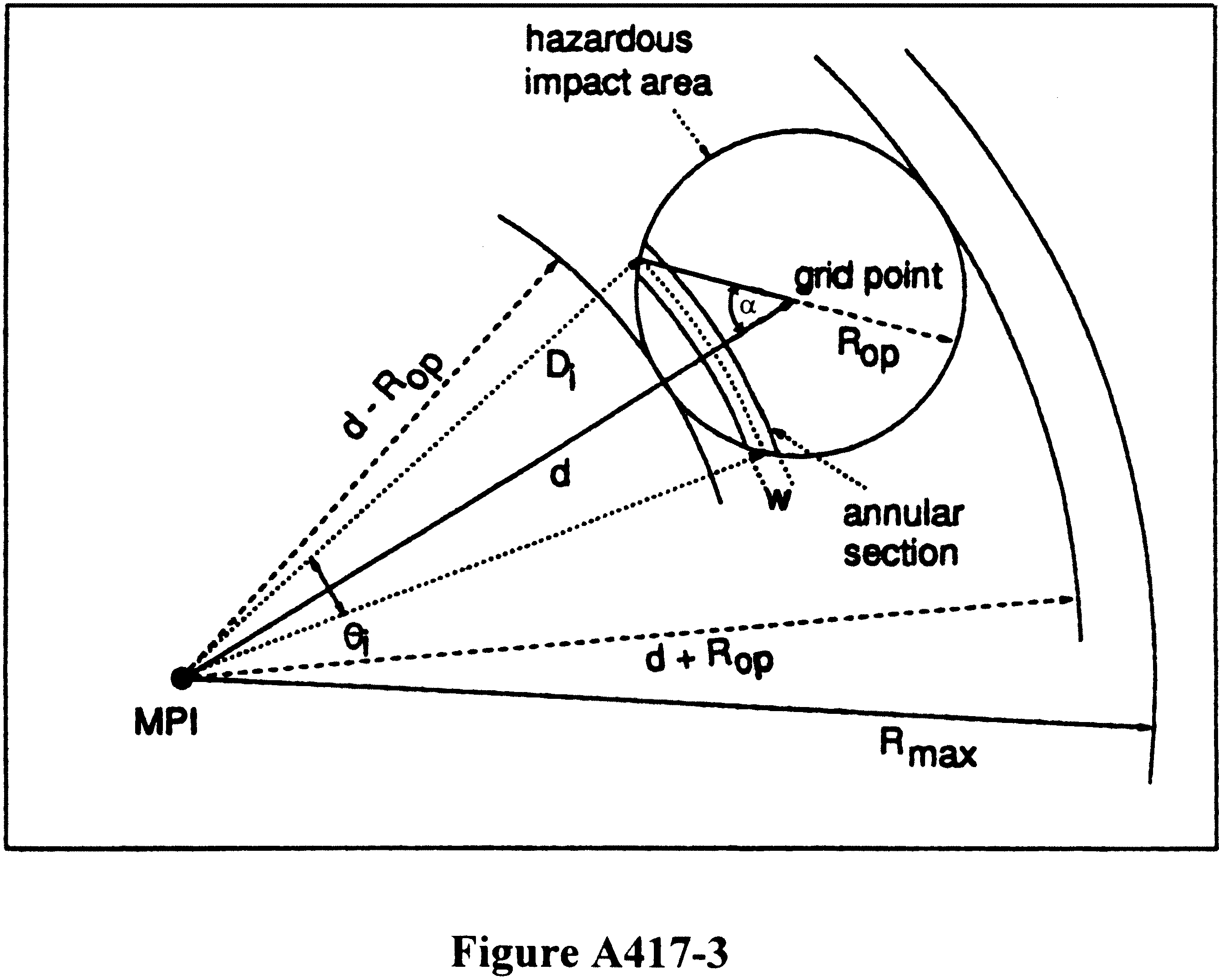
(2) If Di represents the distance from the MPI to the middle arc of the ith truncated slice and w is the width of the slice, the volume under the slice is found by integrating the density function between the range limits of (Di−w/2) and (Di+w/2), and between the angular limits bounded by the sides of the angle θi. The sum for all volumes between the limits of (d−Rop) and (d+Rop) gives the probability of casualty at the grid point for one hazardous area, in one debris class, for one failure-response mode, and, if applicable, one failure time interval. If n is sufficiently large so that w is sufficiently small, a good approximation for the probability of impact in the ith-truncated slice is:

Where:
F(Di) is the density function value at distance Di from the MPI.
w θi Di is the approximate area of the truncated slice.
Slice width w depends on the relative magnitudes of Rmax and (d+Rop).
(3) A second approach must be used if the circularized explosive hazard area about the grid point encompasses the MPI as depicted in figure A417-4.
Start Printed Page 64046
Where:
The circular area of radius Rmax about the MPI represents the limit of all impacts, which is four sigma of the impact dispersion.
d is the distance between the MPI and grid point.
Di is the distance from the MPI to the middle of the ith-truncated slice.
w is the slice width.
(4) For the case illustrated by figure A417-4, (Rop−d) is less than Rmax and the impact density function is first integrated over the small circular area of radius (Rop−d) centered at the MPI, to find the probability of impacting inside this circle. The remainder of the hazardous impact area is sliced into n truncated annular regions, and the impact probability for each slice found by integrating the density function between the range and angular limits of the slice. The probability of casualty at a grid point for explosive or other hazardous debris impacts shall be determined in accordance with the following:

Where:
ρ0 is the probability of impacting in the circular area of radius (Rop−d) centered at the MPI. ρ0 is determined by integrating “n” probability circles to obtain the probability of casualty for the circle with radius of (Rop−d),

ρi is the probability of the ith slice. ρi is computed by integrating slices of width (w) from (Rop−d) to Rop or Rmax, whichever is smallest,

(5) The selected slice width (w) and limits of integration shall be as defined for each situation discussed in paragraph (f) of this section.
(f) Geometric relationships (situations) in the integration process for determining individual risk. In computing the probability that a person located at a grid point will be subjected to a hazard with a hazard radius rh, six geometric situations arise, depending on the relative magnitudes of rh, Rmax, and d. These situations are illustrated in figures A417-5 through A417-10, and are referred to as situations 1 through 6. The 6 situations result in a variance in ring widths, integration step size, and integration limits used in computing the impact probabilities in the m+1 concentric circles about the grid point. This results in variations in Rmax, rh, and d. The term “circle Rmax” or “circle rh” means the circle having a radius of Rmax or rh. The circle Rmax is always centered at the MPI while circles rh are always centered at the grid point being investigated where a person is assumed to be located. As indicated previously, Rmax is equal to a four-sigma debris impact dispersion.
Start Printed Page 64047
(1) Situation (1). The circles Rmax and rh do not overlap (d≥Rmax+ rh), as illustrated in figure A417-5. For this situation the probability of impact in circle rh is zero and no further integration is necessary. PC = 0.
(2) Situation (2). The circle Rmax contains all of circle rh (Rmax≥d+rh), and rh does not contain the MPI (rh≤d), as illustrated in figure A417-6. Situation 2 doesn't have an initial inner circle and the integration limits are d−rh (lower) to d+rh. (Upper). A launch operator's integration process shall incorporate the following:
(i) Compute slice width (w) by:

Where N=100 is arbitrary in this case; N shall be selected so that w is ≥ 10% of σ or the delta integration angle of the target circle is ≥ 10°. Since integration is over π radians, the minimum N is 18.
(ii) Set ρt = 0. Start the integration by establishing the radius to the midpoint of the first slice w as

and the resulting radius becomes:

(iii) Compute FD by:

Where:
D = RS
σ is the circular normal standard deviation of the debris class impact dispersion of the impacting debris.
FD is the probability density function.
(iv) Compute (θ using the Law of Cosines:

Where:
d is the distance from the impact point of the debris class to the grid point (see figure A417-2).
rh is the hazard radius.
(v) Compute the probability of casualty for a slice by:

Where:
PE is the probability of existence for each debris class.
PC is the probability of casualty for each debris class (A, B---N)
(vi) Integrate over the range of n by incrementing n to n +1 and RS to RS + w, and repeating steps (iii) through (v) until n = N.
Start Printed Page 64048
(3) Situation (3). The circle Rmax does not contain all of circle rh (Rmax<d+ rh), and rh does not contain the MPI (rh≤d), as illustrated in figure A417-7. Situation 3 doesn't have an initial inner circle and the integration limits are d−rh (lower) to Rmax (upper).
(i) Compute slice width (w) by:

Where N=100 is arbitrary in this case; N shall be selected so that w is ≥ 10% of σ or the delta integration angle of the target circle is ≥ 10°. Since integration is over π radians, the minimum N is 18.
(ii) Set pt = 0. Start the integration by establishing the radius to the midpoint of the first slice w as

and the resulting radius (see figure A417-3) becomes:

(iii) Compute FD by:
Where:
D = RS.
σ is the circular normal standard deviation of the debris class impact dispersion of the impacting debris.
FD is the probability density function.
(iv) Compute θ using the Law of Cosines:
Where:
d is the distance from the impact point of the debris class to the grid point (see figure A417-2).
rh is the hazard radius.
(v) Compute the probability of casualty for a slice by:
Where:
PE is the probability of existence for each debris class.
PC is the probability of casualty for each debris class (A, B---N)
(vi) Integrate over the range of n by incrementing n to n +1 and RS to RS + w, and repeating steps (iii) through (v) until n = N.
(4) Situation (4). The circle Rmax contains all of circle rh (Rmax ≥d+rh), and rh contains the MPI (rh>d), as illustrated in figure A417-8. The impact probability for the small circle of radius (rh−d) is found by closed-form computation and added to the sum obtained from a step-by-step integration across the remainder of circle rh. Situation 4 has an initial inner circle of radius rh−d and the integration limits are rh−d (lower) to rh+d (upper).
(i) Compute slice width (w) by:

Where N=100 is arbitrary in the case; N shall be selected so that w is ≥10% of σ or the delta integration angle of the target circle is ≥10°. Since integration is over π radians, the minimum N is 18.
(ii) Set Pt = 0. Start the integration by establishing the radius to the midpoint of the first slice w as

and the resulting radius (see figure A417-3) becomes:

(iii) Compute FD by:

Where:
D = RS.
σ is the circular normal standard deviation of the debris class impact dispersion of the impacting debris;
FD is the probability density function.
(iv) Compute θ using the Law of Cosines
Start Printed Page 64049
Where:
d is the distance from the impact point of the debris class to the grid point (see figure A417-2).
rh is the hazard radius.
(v) Compute the probability of casualty for a slice by:

Where:
PE is the probability of existence for each debris class.
PC is the probability of casualty for each debris class (A, B---N)
(vi) Integrate over the range of n by incrementing n to n+1 and RS to RS + w, and repeating steps (iii) through (v) until n = N.
(vii) Compute the casualty probability for the inner circle by subdividing the inner circle with radius rh−d into 10 circles for integration by:

(viii) With rI = wr and AL = 0, repeat the following for 10 summations:


(5) Situation (5). The circle Rmax does not contain all of circle rh (Rmax<d+rh) circle rh contains the MPI (rh>d), and Rmax>rh−d, as illustrated in figure A417-9. The impact probability for the small circle of radius (rh−d) is found by closed-form computation and added to the sum obtained from a step-by-step integration across the remainder of circle rh that is inside circle Rmax. Situation 5 has an initial inner circle of radius rh−d and the integration limits are rh−d (lower) to Rmax (upper).
(i) Compute slice width (w) by:

Where N=100 is arbitrary in this case; N shall be selected so that w is ≥ 10% of σ or the delta integration angle of the target circle is ≥ 10°. Since integration is over π radians, the minimum N is 18.
(ii) Set pt=0. Start the integration by establishing the radius to the midpoint of the first slice w as

and the resulting radius (see figure A417-3) becomes:

(iii) Compute FD by:

Where:
D=RS.
σ is the circular normal standard deviation of the debris class impact dispersion of the impacting debris;
FD is the probability density function.
(iv) Compute θ using the Law of Cosines:

Where:
d is the distance from the impact point of the debris class to the grid point (see figure A417-2).
rh is the hazard radius.
(v) Compute the probability of casualty for a slice by:
Start Printed Page 64050
Where:
PE is the probability of existence for each debris class.
PC is the probability of casualty for each debris class (A, B—N)
(vi) Integrate over the range of n by incrementing n to n+1 and RS to RS + w, and repeating steps (iii) through (v) until n = N.
(vii) Compute the casualty probability for the inner circle by subdividing the inner circle with radius rh −d into 10 circles for integration by:

(viii) With rI = wr and AL = 0, repeat the following for 10 summations:

(6) Situation (6). The circle Rmax is contained inside rh, as illustrated in figure A417-10. The impact probability for the small circle of radius Rmax is one and no integration is necessary.

Table A417-1.—Liquid Propellant Explosive Equivalents
Propellant combinations TNT equivalents LO2/LH2 The larger of 8W2/3 or 14% of W. Where W is the weight of LO2/LH2. LO2/LH2 + LO2/RP-1 Sum of (20% for LO2/RP-1) the larger of 8W2/3 or 14% of W. Where W is the weight of LO2/LH2. LO2/RP-1 20% of W up to 500,000 pounds + 10% of W over 500,000 pounds. Where W is the weight of LO2/RP-1. N2 O4/N2 H4 (or UDMH or UDMH/N2 H4 Mixture) 10% of W2. Where W is the weight of the propellant. Table A417-2.—Propellant Hazard and Compatibility Groupings and Factors To Be Used When Converting Gallons of Propellant Into Pounds
Propellant Hazard group Compatibility group Pounds/gallon °F Hydrogen Peroxide II A 11.6 68 Hydrazine III C 8.4 68 Liquid Hydrogen III C 0.59 −423 Liquid Oxygen II A 9.5 −297 Nitrogen Tetroxide I A 12.1 68 RP-1 I C 6.8 68 UDMH III C 6.6 68 UDHM/Hydrazine III C 7.5 68 Appendix B to Part 417—Methodology for Performing Debris Risk Analysis
B417.1 General
A launch operator's debris risk analysis required by § 417.227 must be in accordance with the analysis constraints contained in § 417.227 and shall be performed using the equations and methodologies for calculating expected casualty (EC) contained in this appendix unless, through the licensing process, the launch operator provides a clear and convincing demonstration that an alternate method provides an equivalent level of safety. A launch operator shall compute the total EC due to debris as the sum of the EC due to all planned debris impacts determined according to B417.3 and the EC due to potential launch vehicle failure along the normal flight path, hereafter referred to as overflight EC, determined in accordance with B417.5. For a launch vehicle that uses a flight termination system, the total EC due to debris must also account for risk to populations outside the flight control lines in accordance with to B417.7.
B417.3 Planned Impact EC
(a) General. A launch operator shall use the equations and methodologies contained in this section for calculating EC for planned debris impacts.
(b) Input for computing planned impact EC. A launch operator shall identify the input parameters in this paragraph for computing the EC for planned debris impacts:
(1) The nominal impact location of each planned debris fragment and the standard deviation (sigma) of the impact dispersion distances from the nominal impact point each of the uprange, downrange, left crossrange, and right crossrange directions. A launch operator shall determine debris impacts and dispersions in accordance with § 417.227(b)(5).
(2) The probability of success of each debris impact, that is, one minus the probability of the launch vehicle failing prior to each debris jettison. The probability of success used for the impact of a planned debris fragment must account for all stages that burn prior to jettison of that debris fragment.
(3) The effective casualty area for each planned impacting debris fragment.
(4) The location and population density of each population center to be evaluated.Start Printed Page 64051
(c) Methodology for computing planned impact EC. A launch operator shall compute the EC for each population center within the five-sigma dispersion of the nominal impact point for each fragment of impacting debris planned as part of normal flight using the equations and steps in this paragraph:
(1) Compute the following for each population center within the five-sigma dispersion of each planned impact of a debris fragment:

Where:
Pi is the probability of the planned debris fragment impacting the population center that has area Ap.
Pf is the failure probability of the launch vehicle prior to the stage or other planned impacting debris jettison.
Pp is the probability of impacting inside the population center with area Ap, assuming a successful flight.
Ap is the area of the population center.
σy is the crossrange standard diviation of the planned impact dispersion for each planned debris fragment.
σx is the downrange standard deviation of the planned impact dispersion for each planned debris fragment.
x and y are the downrange and crossrange distances between the nominal impact point location and the location of the centroid of the population center for each planned debris fragment.
(2) For each immpacting debris fragment, compute EC for all population centers within the five-sigma dispersion using the following:

Where:
Pi is the probability of a planned debris fragment impacting the population center with population density Pd.
AC is the effective casualty area for the planned impacting debris fragment.
Pd is the population density of each population center.
(3) Sum all EC values for all planned impacts to compute the total planned debris impact EC.
B417.5 Methodology for Computing Overflight EC
(a) General. A launch operator shall use the equations and methodologies contained in this section for calculating overflight EC.
(b) Input. A launch operator shall identify the following input parameters:
(1) The nominal launch vehicle trajectory instantaneous impact points as a function of trajectory time and the standard deviation of the normal trajectory impact point dispersion in the crossrange direction for each trajectory time. A launch operator shall use the trajectory data determined in accordance with § 417.205 for an orbital launch or C417.3 of appendix C of this part for the launch of a suborbital rocket.
(2) The failure probability of each launch vehicle stage and the overall launch vehicle failure probability determined in accordance with § 417.227(b)(6).
(3) The effective casualty area for each impacting debris fragment associated with a launch vehicle failure as a function of trajectory time determined in accordance with the debris analysis required by § 417.209.
(c) Methodology for computing overflight EC. A launch operator shall determine overflight EC using the nominal instantaneous impact point data determined by the trajectory analysis performed in accordance with § 417.205(c) for an orbital launch or appendix C of this part for a suborbital launch for each trajectory time, and the following methodology:
(1) Start at liftoff, trajectory time (T)=0.
(2) Increase the distance along the nominal trajectory by one trajectory time interval (ΔT) to T+ΔT. Form a sector by drawing lines perpendicular to the nominal instantaneous impact point trace that intersect the impact point positions at both T and T+ΔT.
(3) Identify all population centers that are contained or partially contained within the sector and that have a left crossrange or right crossrange distance from the nominal instantaneous impact point that is less than or equal to five-sigma of the crossrange trajectory dispersion. If no population centers are identified repeat step (2). For each population center identified calculate the crossrange component of the probability of impact (Py) using the following:

Where:
y is the crossrange distance from the nominal instantaneous impact point trace for the trajectory time being evaluated to the middle of the population center.
σy is the crossrange standard deviation for the trajectory time being evaluated.
Δy is the crossrange width of the population center for the trajectory time interval being evaluated. For computational purposes, Δy must not exceed one half the value of σy. If so, Δy shall be broken into equal parts with each part less than one half of the value of σy. Py of each part must then be computed and summed to obtain the entire Py.
(4) Calculate the probability of impact (Pi) for the overflight of each population center as follows:

Where:
Pf is the launch vehicle failure rate for the trajectory time interval being evaluated. A launch operator shall apply the failure rate for the launch vehicle stage that will be thrusting during the trajectory time interval being evaluated (if that specific failure rate is known) or the launch operator shall use the launch vehicle failure rate for the entire flight.
TD is dwell time of the instantaneous impact point over the population center during the trajectory time interval being evaluated, assuming the launch vehicle flies a normal trajectory over the centroid of the population center. In each case TD must be less than or equal to ΔT.
TB is the burn time. If a launch operator uses a stage failure rate for Pf, TB must be the burn time for that stage. If the launch operator uses the launch vehicle failure rate for the entire flight for Pf, TB must equal the total launch vehicle burn time for all stages.
The ratio of TD over TB is the downrange component of the probability of impact for the population center being evaluated.
(5) For the current trajectory time, calculate EC for each population center using the following:

Where:
Pi is the probability of impacting the population center with population density Pd.
AC is the sum total effective casualty area that accounts for all impacting debris fragment associated with a launch vehicle failure for the current trajectory time.
Pd is the population density of each population center.
The product of AC·Pd shall be limited to no greater than the total population of the population center being evaluated.
(6) Repeat steps (2) through (5) for all trajectory time intervals until orbit or impact of the final stage is achieved. Sum all EC values for all population centers and for all trajectory time intervals to determine the total overflight EC. Start Printed Page 64052
B417.7 EC for Populations Outside Flight Control Lines
(a) General. For a launch vehicle that uses a flight termination system, a launch operator shall use the equations and methodologies contained in this section to identify any populations outside the flight control lines in the area surrounding the launch point that could be exposed to significant risk due to impacting launch vehicle debris. The risk to such populations must be accounted for in the launch operator's debris risk analysis in accordance with § 417.227(b)(11).
(b) Populations outside the flight control lines. To determine if a debris risk analysis is required for populations outside the flight control lines, a launch operator shall compare population densities in sectors about the launch point to the population limits shown in figures B417.7-1 through B417.7-4 for the launch operator's launch vehicle type. Launch vehicle types are defined in paragraph (c) of this section. The launch operator shall determine the population densities in each sector based on the most current census data and projections for the date and time of flight.
(c) Population limits. Figures B417-1 through B417-4 and their accompanying tables identify population sectors around a launch point and the population limits for each sector as a function of the size of the launch vehicle and whether it is a new or mature launch vehicle. A launch operator shall use the population limits for a mature launch vehicle if its launch vehicle has flown more than 30 times and the launch operator demonstrates that the total vehicle failure rate is less than 10%. Otherwise, the launch operator shall use the population limits for a new launch vehicle. A launch operator shall use the population limits for a large launch vehicle if its launch vehicle is capable of lifting an 18,500-pound payload to a 100-nautical mile orbit or larger. Otherwise, a launch operator shall use the population limits for a medium or small launch vehicle. A launch operator shall determine the population limits that apply to its analysis in accordance with the following:
(1) For a large mature launch vehicle. A launch operator shall use the sector population limits labeled in figure B417-1.
(2) For a medium or small mature launch vehicle. A launch operator shall use the sector population limits in figure B417-2.
(3) For a large new launch vehicle. A launch operator shall use the sector population limits in figures B417-3.
(4) For a medium or small new launch vehicle. A launch operator shall use the sector population limits in figures B417-4.
(5) If a medium or small launch vehicle uses solid rocket motors in any stage other than the first stage, the tables for a large launch vehicle must be used.
(6) If a large launch vehicle uses solid rocket motors in any stage other than the first stage, it must be evaluated on a case by case basis.
(d) Methodology for screening populations outside flight control lines. A launch operator shall use the populations determined in accordance with paragraph (b) of this section and the sector population limits determined in accordance with paragraph (c) of this section to identify any populations outside flight control lines for which debris risk analysis must be performed. The launch operator shall screen the populations in each sector identified in figures B417-1 through B417-4 in accordance with the following:
(1) The launch operator shall compare the population in each sector with the population limit for each sector as determined according to paragraphs (b) and (c) of this section. If the population in a sector exceeds the population limit for that sector, the launch operator shall perform a debris risk analysis for that sector in accordance with paragraph (e) of this section.
(2) For all sectors with a population that is less than the limit, the launch operator shall determine the total population ratio by summing the ratios of the population to the population limit for all sectors. If the sum of population ratios for all sectors is greater than 1.0, the launch operator shall perform a debris risk analysis for a sufficient number of sectors to reduce the sum of population ratios of the remaining sectors to less than 1.0.
(e) Debris risk analysis for populations outside flight control lines. A launch operator shall perform an analysis to determine EC for each population sector requiring a debris risk analysis as determined according to paragraph (d) of this section. The launch operator shall demonstrate the validity of such an analysis on a case-by-case basis through the licensing process. The launch operator's analysis must be in accordance with the following:
(1) The analysis must account for:
(i) All launch vehicle failure response modes and their probability of occurrence.
(ii) Potential launch vehicle failures beginning at liftoff and for each nominal trajectory time at intervals of no greater than two seconds.
(iii) The effects of intact launch vehicle impacts and potential launch vehicle breakup resulting from vehicle turns that exceed structural limits, and in accordance with the probability of their occurrence.
(iv) For launch vehicle breakup, the analysis must account for all debris impact locations and debris dispersion. The debris dispersion must account for inadvertent separation destruct system time delays, variances in impacts caused by winds, differences in debris ballistic coefficient, drag uncertainties, and breakup imported velocities.
(v) The probability density function for each debris class and for each launch vehicle failure response mode.
(vi) The inert and explosive debris effects on casualty area. For inert debris fragments the analysis must account for the effects of bounce, splatter, and slide.
(vii) The population density for each population center located within each sector being evaluated.
(viii) For each population center within the sector, the analysis must account for the probabilities of casualty from all debris, for all failure times, and all launch vehicle failure responses.
(2) Beginning at liftoff, trajectory time = 0, and for each nominal trajectory time, at intervals of no greater than two seconds, the launch operator shall compute EC for each population center within each sector being evaluated and for each potential debris impact. The potential debris impacts must include potential launch vehicle intact impact and the impact of debris fragments resulting from breakup. The launch operator shall use the following equation:

Where:
Pi is the probability of the debris being evaluated impacting within the population center being evaluated for the trajectory time being evaluated.
AC is the effective casualty area for the impacting debris.
Pd is the population density of the population center being evaluated located within the sector.
PFSS is the probability of failure of the launch operator's flight safety system. A launch operator may use 0.002 as the flight safety system probability of failure if the flight safety system is in compliance with the flight safety system requirements of subpart D of this part. For an alternate flight safety system approved in accordance with § 417.107(a)(3), the launch operator shall demonstrate the validity of the probability of failure on a case-by-case basis through the licensing process.
(3) The launch operator shall sum the EC values for each potential debris impact, for each population center within a population sector being evaluated, and for each trajectory time and include this sum in the total EC due to debris for the launch.
Start Printed Page 64053
Start Printed Page 64054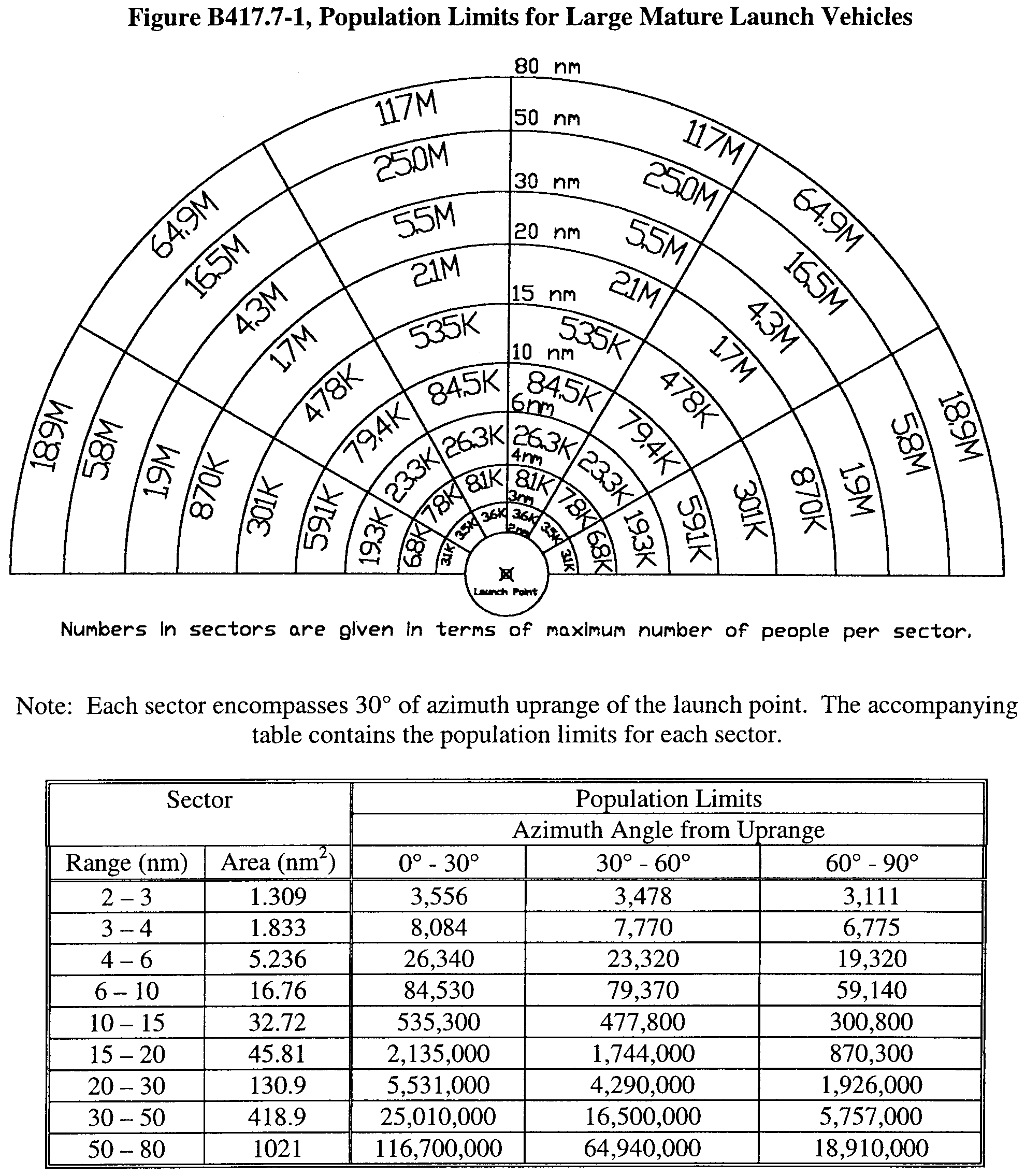
Start Printed Page 64055
Start Printed Page 64056

B417.9 Alternative Debris Risk Analysis
(a) A launch operator may elect to simplify a debris risk analysis by making conservative assumptions that would lead to an overestimation of the total EC due to debris. The intent of such an analysis would be to show that the overestimated EC does not exceed the public safety criteria required by § 417.107(b). Such an analysis must be approved by the FAA during the licensing process. In addition to the analysis products required by § 417.227, a launch operator shall submit the following with respect to an alternative analysis:
(1) Identification of all assumptions made and explanation of how they relate to the debris risk analysis defined in B417.3, B417.5, and B417.7 of this appendix.
(2) Demonstration of how each assumption leads to overestimation of the total EC due to debris.
(b) The following are examples of simplifications to the debris risk analysis that may be acceptable for a specific launch scenario:
(1) When flying over a remote area with limited population density, it may suffice to assume that Pi has a value of 1.0 for all population centers being evaluated.
(2) When computing overflight EC, a launch operator may choose to analyze a worst case flight trajectory within the five-sigma corridor.
(3) A launch operator may choose to combine population centers and assume a Start Printed Page 64057worst case population density for the combined area.
(4) A launch operator may choose to assume a worst case population density for the entire local launch area.
(5) A launch operator may choose to assume a worst case effective casualty area.
(c) A launch operator may employ an alternative analytical approach if the launch operator demonstrates, clearly and convincingly through the licensing process, that the proposed alternative provides an equivalent level of safety. The following requirements apply to any such alternative:
(1) The launch operator must demonstrate that any changes in inputs and assumptions are reasonable, based on accurate data, and statistically valid.
(2) A launch operator shall use the equations for calculating collective debris expected casualty required in this appendix.
(3) Use of risk analysis models such as those used at federal launch ranges in conjunction with validated input data, Monte Carlo simulation approaches, and refined (that is, higher fidelity) population data may constitute acceptable tools in support of a launch operator's alternative analysis.
(4) A launch operator may perform a sheltering analysis as a means of refining expected casualty calculations if the launch operator demonstrates that the analysis is reasonable, based on accurate data, and statistically valid. Rather than assuming that all people are in the open, a sheltering analysis accounts for populations that would be within a structure that may or may not provide the people some protection during the flight of a launch vehicle. Any sheltering analysis must account for any debris that will collapse or penetrate a structure and the increased casualty area that would result from such an event.
Appendix C to Part 417—Flight Safety Analysis for an Unguided Suborbital Rocket Flown With a Wind Weighting Safety System and Hazard Areas for Planned Impacts for All Launches
C417.1 General
This appendix contains methodologies for performing the flight safety analysis required for the launch of an unguided suborbital rocket flown with a wind weighting safety system. A launch operator shall perform a flight safety analysis to determine the launch parameters and conditions under which an unguided suborbital rocket may be flown using a wind weighting safety system in accordance with § 417.235. The results of this analysis must show that any adverse effects resulting from flight will be contained within controlled operational areas and any flight hardware or payload impacts will occur within planned impact areas. The flight safety analysis must demonstrate compliance with the safety criteria and operational requirements for the launch of an unguided suborbital rocket contained in § 417.125. A launch operator shall ensure that the flight safety analysis for an unguided suborbital rocket is conducted in accordance with the methodologies provided in this appendix unless the launch operator demonstrates, through the licensing process, that an alternate method provides an equivalent level of safety.
C417.3 Trajectory Analysis
(a) General. A launch operator shall perform a trajectory analysis for the flight of an unguided suborbital rocket to determine the launch vehicle's nominal trajectory, nominal drag impact points, and potential three-sigma dispersions about each nominal drag impact point.
(b) Definitions. A launch operator shall employ the following definitions when determining an unguided suborbital rocket's trajectory and drag impact points:
(1) Drag impact point means the intersection of a predicted ballistic trajectory of an unguided suborbital rocket stage or other impacting component with the Earth's surface. A drag impact point reflects the effects of atmospheric influences as a function of drag forces and mach number.
(2) Maximum range trajectory means an optimized trajectory, extended through fuel exhaustion of each stage, to achieve a maximum downrange drag impact point.
(3) Nominal trajectory means the trajectory that an unguided suborbital rocket will fly if all rocket aerodynamic parameters are as expected without error, all rocket internal and external systems perform exactly as planned, and there are no external perturbing influences, such as winds, other than atmospheric drag and gravity.
(4) Normal flight means all possible trajectories of a properly performing unguided suborbital rocket whose drag impact point location does not deviate from its nominal location more than three sigma in each of the uprange, downrange, left crossrange, or right crossrange directions.
(5) Performance error parameter means a quantifiable perturbing force that contributes to the dispersion of a drag impact point in the uprange, downrange, and cross-range directions of an unguided suborbital rocket stage or other impacting launch vehicle component. Performance error parameters for the launch of an unguided suborbital rocket reflect rocket performance variations and any external forces that can cause offsets from the nominal trajectory during normal flight. Performance error parameters include thrust, thrust misalignment, specific impulse, weight, variation in firing times of the stages, fuel flow rates, contributions from the wind weighting safety system employed, and winds.
(c) Input. A trajectory analysis requires the inputs necessary to produce a six-degree-of-freedom trajectory. When employing commercially available trajectory software or any trajectory software developed specifically for a launch, a launch operator must identify the following as inputs to the trajectory computations:
(1) Launcher data. Geodetic latitude and longitude; height above sea level; location errors; and launch azimuth and elevation.
(2) Reference ellipsoidal earth model. Name of the earth model employed, semi-major axis, semi-minor axis, eccentricity, flattening parameter, gravitational parameter, rotation angular velocity, gravitational harmonic constants, and mass of the earth.
(3) Vehicle characteristics for each stage. A launch operator shall identify the following for each stage of an unguided suborbital rocket's flight:
(i) Nozzle exit area of each stage.
(ii) Distance from the rocket nose-tip to the nozzle exit for each stage.
(iii) Reference drag area and reference diameter of the rocket including any payload for each stage of flight.
(iv) Thrust as a function of time.
(v) Propellant weight as a function of time.
(vi) Coefficient of drag as a function of mach number.
(vii) Distance from the rocket nose-tip to center of gravity as a function of time.
(viii) Yaw moment of inertia as a function of time.
(ix) Pitch moment of inertia as a function of time.
(x) Pitch damping coefficient as a function of mach number.
(xi) Aerodynamic damping coefficient as a function of mach number.
(xii) Normal force coefficient as a function of mach number.
(xiii) Distance from the rocket nose-tip to center of pressure as a function of mach number.
(xiv) Axial force coefficient as a function of mach number.
(xv) Roll rate as a function of time.
(xvi) Gross mass of each stage.
(xvii) Burnout mass of each stage.
(xviii) Vacuum thrust.
(xix) Vacuum specific impulse.
(xx) Stage dimensions.
(xxi) Weight of each spent stage.
(xxii) Payload mass properties.
(xxiii) Nominal launch elevation and azimuth.
(4) Launch events. Stage ignition times, stage burn times, and stage separation times, referenced to ignition time of first stage.
(5) Atmosphere. Density as a function of altitude, pressure as a function of altitude, speed of sound as a function of altitude, temperature as a function of altitude.
(6) Wind errors. Error in measurement of wind direction as a function of altitude and wind magnitude as a function of altitude, wind forecast error, such as error due to time delay from wind measurement to launch.
(d) Methodology for determining the nominal trajectory and nominal drag impact points. A launch operator shall employ steps (d)(1)-(d)(3) of this section to determine the nominal trajectory and the nominal drag impact point locations for each impacting rocket stage and component:
(1) A launch operator shall identify each performance error parameter associated with the unguided suborbital rocket's design and operation and the value for each parameter that reflect nominal rocket performance. These performance error parameters include thrust misalignment, thrust variation, weight variation, fin misalignment, impulse variation, aerodynamic drag variation, staging timing variation, stage separation-force variation, drag error, uncompensated wind, launcher elevation angle error, launcher azimuth angle error, launcher tip-off, and launcher location error.
(2) A launch operator shall perform a no-wind trajectory simulation using a six-degrees-of-freedom (6-DOF) trajectory simulation with all performance error Start Printed Page 64058parameters set to their nominal values to determine the impact point of each stage or component. The 6-DOF trajectory simulation must provide rocket position translation along three axes of an orthogonal earth centered coordinate system and rocket orientation in roll, pitch and yaw. The 6-DOF trajectory simulation must compute the translations and orientations in response to forces and moments internal and external to the rocket including the effects of the input data required in paragraph (c) of this section. The FAA will permit a launch operator to incorporate the following assumptions in a 6-DOF trajectory simulation:
(i) The airframe may be treated as a rigid body.
(ii) The airframe may have a plane of symmetry coinciding with the vertical plane of reference.
(iii) The vehicle may assume to have aerodynamic symmetry in roll.
(iv) The airframe may have six degrees-of-freedom.
(v) The aerodynamic forces and moments may be functions of mach number and may be linear with small flow incidence angles of attack.
(3) A launch operator shall tabulate the geodetic latitude and longitude of the launch vehicle's nominal drag impact point as a function of trajectory time and the final nominal drag impact point of each planned impacting stage or component.
(e) Methodology for determining maximum downrange drag impact points. A launch operator shall compute the maximum possible downrange drag impact point for each rocket stage and impacting component. A launch operator shall use the nominal drag impact point methodology defined in paragraph (d) of this section modified to optimize the unguided suborbital rocket's performance and flight profile to create the conditions for a maximum downrange drag impact point, including fuel exhaustion for each stage and impacting component.
(f) Methodology for computing drag impact point dispersions. A launch operator shall employ the steps in paragraphs (f)(1)-(f)(3) of this section when determining the dispersions in terms of drag impact point distance standard deviations in uprange, downrange, and crossrange direction from the nominal drag impact point location for each stage and impacting component:
(1) For each stage of flight, a launch operator shall identify the plus and minus one-sigma values for each performance error parameter identified in accordance with paragraph (d)(1) of this section (i.e., nominal value plus one standard deviation and nominal value minus one standard deviation). A launch operator shall determine the dispersion in downrange, uprange, and left and right crossrange for each impacting stage and component. This is done by either performing a Monte Carlo analysis that assumes a normal distribution of each performance error parameter or by determining the dispersion by a root-sum-square method in accordance with paragraph (f)(2) of this section.
(2) When using a root-sum-square method to determine dispersion, a launch operator shall determine the deviations for a given stage by evaluating the deviations produced in that stage due to the performance errors in that stage and all preceding stages of the launch vehicle as illustrated in Table C417-1, and by computing the square root of the sum of the squares of each deviation caused by each performance error parameter's one sigma dispersion for each stage in each of the right crossrange, left crossrange, uprange and downrange directions. A launch operator shall evaluate the performance errors for one stage at a time, with the performance of all subsequent stages assumed to be nominal. A launch operator's root-sum-square method must incorporate the following requirements:
Table C417-1.—Illustrative simulation runs required to determine drag impact point dispersions for a three stage launch vehicle.
Trajectory simulation runs stage performance error parameters Dispersion being determined Stage 1 Stage 2 Stage 3 Stage 1 errors X 1 Stage 1 errors, Stage 2 nominal X Stage 1 nominal, Stage 2 errors X Stage 1 errors, Stage 2 nominal, Stage 3 nominal X Stage 1 nominal, Stage 2 errors, Stage 3 nominal X Stage 1 nominal, Stage 2 nominal, Stage 3 errors X 1 An X in a given stage column indicates that the noted simulation runs are required to determine the dispersion for that stage. (i) With the 6-DOF trajectory simulation used to determine nominal drag impact points in accordance with paragraph (d) of this section, perform a series of trajectory simulation runs for each stage and planned ejected debris such as a fairing, payload, or other component, and, for each simulation, model only one performance error parameter set to either its plus or minus one-sigma value. All other performance error parameters for a given simulation run must be set to their nominal values. Continue until a trajectory simulation run is performed for each plus one-sigma performance error parameter value and each minus one-sigma performance error parameter value for the stage or the planned ejected debris being evaluated. For each trajectory simulation run and for each impact being evaluated, tabulate the downrange, uprange, left crossrange, and right crossrange drag impact point distance deviations measured from the nominal drag impact point location for that stage or planned debris.
(ii) For uprange, downrange, right crossrange, and left crossrange, compute the square root of the sum of the squares of the distance deviations in each direction. The square root of the sum of the squares distance value for each direction represents the one-sigma drag impact point dispersion in that direction. For a multiple stage rocket, perform the first stage series of simulation runs with all subsequent stage performance error parameters set to their nominal value. Tabulate the uprange, downrange, right crossrange, and left crossrange distance deviations from the nominal impact for each subsequent drag impact point location caused by the first stage one-sigma performance error parameter. Use these deviations in determining the total drag impact point dispersions for the subsequent stage impacts as described in paragraph (f)(2)(iii) of this section.
(iii) For each subsequent stage impact of an unguided suborbital rocket, determine the one-sigma impact dispersions by first determining the one-sigma distance deviations for that stage impact caused by each preceding stage as described in paragraph (f)(2)(ii) of this section. Then perform a series of simulation runs and tabulate the uprange, downrange, right crossrange, and left crossrange drag impact point distance deviations as described in paragraph (f)(2)(i) for that stage's one-sigma performance error parameter values with the preceding stage performance parameters set to nominal values. For each uprange, downrange, right crossrange, and left crossrange direction, compute the square root of the sum of the squares of the second stage impact distance deviations due to that stage's and each preceding stage's one-sigma performance error parameter values. This square root of the sum of the squares distance value for each direction represents the total one-sigma drag impact point dispersion in that direction for the nominal drag impact point location of that stage. Use these deviations when determining the total drag impact point dispersions for the subsequent stage impacts.
(3) A launch operator shall determine a three-sigma dispersion area for each impacting stage or component as an ellipse that is centered at the nominal drag impact point location and has semi-major and semi-minor axes along the uprange, downrange, left crossrange, and right crossrange axes. The length of each axis must be three times as large as the total one-sigma drag impact point dispersions in each direction. Start Printed Page 64059
(g) Trajectory analysis products for a suborbital rocket. A launch operator shall submit the following products of a trajectory analysis for an unguided suborbital rocket to the FAA in accordance with § 417.235(g):
(1) A description of the process that the launch operator used for performing the trajectory analysis including the number of simulation runs and the process for any Monte Carlo analysis performed.
(2) A description of all assumptions and procedures the launch operator used in deriving each of the performance error parameters and their standard deviations.
(3) Launch point origin data: name, geodetic latitude (+N), longitude (+E), geodetic height, and launch azimuth measured clockwise from true north.
(4) Name of reference ellipsoid earth model used. If a launch operator employs a reference ellipsoid earth model other than WGS-84, Department of Defense World Geodetic System, Military Standard 2401 (Jan. 11, 1994), a launch operator shall identify the semi-major axis, semi-minor axis, eccentricity, flattening parameter, gravitational parameter, rotation angular velocity, gravitational harmonic constants (e.g., J2, J3, J4), and mass of earth.
(5) If a launch operator converts latitude and longitude coordinates between different ellipsoidal earth models to complete a trajectory analysis, the launch operator shall submit the equations for geodetic datum conversions and a sample calculation for converting the geodetic latitude and longitude coordinates between the models employed.
(6) A launch operator shall submit tabular data that lists each performance error parameter used in the trajectory computations and each performance error parameter's plus and minus one-sigma values. If the launch operator employs a Monte Carlo analysis method for determining the dispersions about the nominal drag impact point, the tabular data must list the total one-sigma drag impact point distance deviations in each direction for each impacting stage and component. If the launch operator employs the square root of the sum of the squares method described in paragraph (f)(2) of this section, the tabular data must include the one-sigma drag impact point distance deviations in each direction due to each one-sigma performance error parameter value for each impacting stage and component.
(7) A launch operator shall submit a graphical depiction showing geographical landmasses and the nominal and maximum range trajectories from liftoff until impact of the final stage. The graphical depiction must plot trajectory points in time intervals of no greater than one second during thrusting flight and for times corresponding to ignition, thrust termination or burnout, and separation of each stage or impacting body. If there are less than four seconds between stage separation or other jettison events, a launch operator must reduce the time intervals between plotted trajectory points to 0.2 seconds or less. The graphical depiction must show total launch vehicle velocity as a function of time, present-position ground-range as a function of time, altitude above the reference ellipsoid as a function of time, and the static stability margin as a function of time.
(8) A launch operator shall submit tabular data that describes the nominal and maximum range trajectories from liftoff until impact of the final stage. The tabular data must include the time after liftoff, altitude above the reference ellipsoid, present position ground range, and total launch vehicle velocity for ignition, burnout, separation, booster apogee, and booster impact of each stage or impacting body. The launch operator shall submit the tabular data for the same time intervals required by paragraph (g)(7) of this section.
(9) A launch operator shall submit a graphical depiction showing geographical landmasses and the unguided suborbital rocket's drag impact point for the nominal trajectory, the maximum impact range boundary, and the three-sigma drag impact point dispersion area for each impacting stage or component. The graphical depiction must show the following in relationship to each other: the nominal trajectory, a circle whose radius represents the range to the farthest downrange impact point that results from the maximum range trajectory, and the three-sigma drag impact point dispersions for each impacting stage and component.
(10) A launch operator shall submit tabular data that describes the nominal trajectory, the maximum impact range boundary, and each three-sigma drag impact point dispersion area. The tabular data must include the geodetic latitude (positive north of the equator) and longitude (positive east of the Greenwich Meridian) of each point describing the nominal drag impact point positions, the maximum range circle, and each three-sigma impact dispersion area boundary. Each three-sigma dispersion area shall be described by no less than 20 coordinate pairs. All coordinates must be rounded to the fourth decimal point.
C417.5 Hazard Area Analysis
(a) General. A launch operator shall perform a hazard area analysis for the flight of an unguided suborbital rocket as required by § 417.235(c). A launch operator shall establish hazard areas to protect the public from planned events during the flight of an unguided suborbital rocket. A launch operator's hazard area analysis must determine a flight hazard area around the launch point and impact hazard areas, aircraft hazard areas, and ship hazard areas for each impacting stage and component in accordance with this section. Requirements for a launch operator's implementation of a hazard area are contained in § 417.121(e) and § 417.121(f) of part 417.
(b) Hazard area analysis input. A launch operator shall employ the following inputs to determine each hazard area for the flight of an unguided suborbital rocket:
(1) The launch vehicle downrange, uprange, and crossrange impact dispersion determined in accordance with C417.3 of this appendix.
(2) Latitude and longitude of the nominal impact point of each impacting stage and impacting component determined in accordance with C417.3 of this appendix.
(3) Total propellant weight and propellant type for each rocket stage.
(c) Methodology for computing a flight hazard area. A launch operator shall determine a flight hazard area for the flight of an unguided suborbital rocket in accordance with the following:
(1) On the surface of the Earth, a flight hazard area must encompass the blast area surrounding the launch point. A launch operator shall calculate a blast hazard area for an overpressure of 3.0 pounds per square inch that is defined by a circle with the launch point at its center and with a radius R determined using the following equation:
R = 20.3 (NEW)1/3
Where:
R is in feet.
NEW = Net explosive weight = W×C
W is the propellant weight in pounds.
C is the TNT equivalency coefficient of the propellant being evaluated. A launch operator shall identify the TNT equivalency of each propellant on its launch vehicle, including any payload. TNT equivalency data for common liquid propellants is provided in tables C417-2. Table C417-3 provides factors for converting gallons of specified liquid propellants to pounds.
(2) In addition to the area on the surface of the Earth determined according to paragraph (c)(1) of this section, for the protection of aircraft, a launch operator's flight hazard area must include an air space region that encompasses the unguided suborbital rocket's three-sigma trajectory dispersion from the Earth's surface at the launch point to an altitude of 60,000 feet.
(d) Maximum impact range area. A launch operator shall define a maximum impact range area as a circle with a radius equal to the range of the furthest maximum downrange impact point determined according to C417.3(e).
(e) Impact hazard areas. A launch operator shall determine an impact hazard area for each impacting stage and component as depicted in Figure C417-1.
(f) Planned impact aircraft hazard area. A launch operator shall employ the methodology described in this paragraph to determine an aircraft hazard area for each planned impact of a launch vehicle stage or component for all suborbital and orbital launches. A launch operator shall compute an aircraft hazard area for each planned impact of a launch vehicle stage or component in accordance with the following:
(1) An aircraft hazard area must be a three dimensional air space region from the Earth's surface to an altitude of 60,000 feet that encompasses, for all altitudes, the larger of the three-sigma drag impact ellipse determined in accordance with C417.3(f)(3) or the ellipse with the same semi-major and semi-minor axis ratio as the impact dispersion, where, if an aircraft were located on the boundary of the ellipse, the probability of hitting the aircraft would be less than or equal to 1×10⁻⁸ determined in accordance with paragraph (f)(2) of this section. An example aircraft hazard area is illustrated in Figure C417-2. For the launch of an unguided suborbital rocket, if the impact of a stage or component has a three-Start Printed Page 64060sigma dispersion that results in an aircraft hazard area that is prohibitively too large to implement with air traffic control (ATC), a launch operator may employ an alternate aircraft hazard area. A launch operator shall provide a clear and convincing demonstration, through the licensing process, that any alternate aircraft hazard area provides an equivalent level of safety to the requirements of this section based on analysis of the proposed launch and potential air traffic in the impact hazard area.
(2) A launch operator shall determine an aircraft hazard area ellipse where, if an aircraft were located on the boundary of the ellipse, the probability of hitting the aircraft would be less than or equal to 1×10⁻⁸. A launch operator shall use the dimensions of the largest aircraft in the vicinity or, if unknown, the dimensions of a Boeing 747 aircraft. A launch operator shall compute an aircraft hazard area to demonstrate the probability of impact in accordance with the following:
(i) Employ the actual speed of the largest aircraft in the vicinity, or assume the aircraft is traveling at mach 0.8 velocity.
(ii) Determine the distance the aircraft travels during the time that the stage or ejected debris falls through a distance equal to twice the length of the debris plus the depth of the aircraft. The aircraft speed, assuming mach 0.8 if unknown, and the time it takes the debris to fall through the depth of the aircraft determine the distance of travel. A launch operator shall use the following equations to make this determination:

Where:
β is the ballistic coefficient of the stage or ejected debris in pounds per square foot.
W is the weight of the stage or ejected debris in pounds.
A is the area of the stage or ejected debris.
Cd is the coefficient of drag (dimensionless) of the stage or ejected debris.
VZ is the velocity of the stage or ejected debris in the altitude axis.
g is the gravity constant.
ρ is the density of the atmosphere at the assumed aircraft height in pounds per cubic foot.
Ta is the time that the debris falls through a distance equal to twice the length of the stage or ejected debris plus the depth of the aircraft.
Ha is the depth of the aircraft.
LR is the length of the stage or ejected debris.
Va is the aircraft's velocity or 0.8 mach if aircraft velocity is unknown.
Dx is the distance traveled during time Ta.
(iii) The distance of the aircraft from the nominal impact point shall be varied with a constant number of sigma increase in both downrange and crossrange until a probability of impact of ≤ 1×10⁻⁸ is obtained. This shall be accomplished using the following:

Where:
ASA is the area traveled by the aircraft during Ta
La is the distance from wing tip to wing tip of the aircraft.
Start at σc = and iterate the following until PA is less than 1×10⁻⁸:

Repeat the iteration until PA is less than 1×10⁻⁸.
Where:
σx is the one sigma distance of debris impact in the downrange direction. σy is the one sigma distance of debris impact in the crossrange direction.
y is the crossrange distances from the nominal impact point to the assumed position of the aircraft.
PA is the aircraft impact probability.
(iv) Once PA is less than 1×10⁻⁸, the aircraft hazard area shall be defined by the following elliptical semi axes:

(3) A launch operator shall determine the time period during which an aircraft hazard area must be in effect. The launch operator shall ensure that an aircraft hazard area remains in effect from before liftoff until after the launch vehicle stage or component impact has occurred. The time that the hazard area is in effect, through completion of launch, must be greater than the impact time of the smallest hazardous debris piece.
(g) Collective ship-hit probability analysis for planned impacts. A launch operator shall use statistical ship density data to determine the collective ship-hit probability for each planned impacting stage or component, in accordance with the requirements of this paragraph, to determine whether the launch operator must survey the impact area for ships and to determine flight commit criteria. If a launch operator demonstrates that the collective ship-hit probability for an impacting stage or component is less than or equal to 1×10⁻⁵, a launch operator shall define a ship hazard area, in accordance with paragraph (h) of this section, for which the launch operator need not perform flight day surveillance. If the launch operator fails to demonstrate that the collective ship-hit probability for an impacting stage or component is less than 1×10⁻⁵, the launch operator shall perform either a flight day ship-hit probability computation using actual ship location data obtained through surveillance or define the ship-hit ellipses according to paragraph (i) of this section, which the launch operator shall survey on the day of flight. A launch operator's analysis for determining collective ship-hit probability using statistical ship density data must satisfy the following requirements:
(1) A launch operator's analysis must account for the ship density in the three-sigma impact dispersion ellipse surrounding each planned stage or component drag impact point location determined in accordance with C417.3(f)(3). The launch operator shall establish ship density based on the most recent statistical data from maritime reports, satellite analysis, or U.S. government information. The ship density must account for time of day and any other factors that might affect the ship density. The statistical ship density for the impact dispersion ellipse must be multiplied by a safety factor of 10 for use in the collective ship-hit probability analysis unless the launch operator demonstrates the accuracy of its ship density data, clearly and convincingly through the licensing process, and accounts for the associated ship density error in the collective ship-hit probability analysis.
(2) A collective ship-hit probability analysis must use the ship density determined in accordance with paragraph (g)(1) of this section to compute the collective ship-hit probability that exists within the three-sigma impact dispersion ellipse surrounding the nominal drag impact point. The analysis shall be performed by computing the collective ship-hit probability for a series of points located one nautical mile apart within the three-sigma impact dispersion ellipse. A launch operator may assume symmetry in all four quadrants of the three-sigma impact dispersion ellipse. Therefore, the series of points evaluated need only cover the area within one quadrant of the ellipse. A launch operator shall assume that the number of ships at each grid point is equal to the ship density established as the number of ships per square nautical mile. A launch operator shall employ the following procedure and steps to compute the collective ship-hit probability (PS):
(i) Set x = 0.5 (nautical miles) and y = 0.5 (nautical miles).
(ii) Compute PA and PS using the following equations:
Start Printed Page 64061
Where:
PA is the ship-hit probability for each ship location evaluated.
PS is the collective ship-hit probability and is a running sum total of PA for all the ship locations evaluated.
The multiplication factor “4” in the equation for PS accounts for the four quadrants of the ellipse.
NS is the number of ships per square mile.
σx is the one-sigma distance of the debris impact dispersion in the downrange direction in nautical miles.
σy is the one-sigma distance of the debris impact dispersion in the crossrange direction in nautical miles.
x and y are the downrange and crossrange distances, respectively, from the nominal impact point to the assumed position of the ship in nautical miles.
Asa is the area of the NS ships in square nautical miles. A launch operator shall assume a ship size of 120,000 square feet, unless the launch operator provides a clear and convincing demonstration that a smaller ship size is the greatest ship size in the vicinity of the planned impact.
(iii) If the current value of y is equal to or less than the crossrange distance to the three-sigma impact dispersion ellipse for the current downrange value of x, increase y by 1 nautical mile and repeat step (ii).
(iv) If the current value of y is greater than the crossrange distance to the three-sigma impact dispersion ellipse for the current downrange value of x, reset y to 0.5 nautical miles.
(v) If the current value of x is equal to or less than the downrange distance to the three-sigma impact dispersion ellipse for the crossrange value of 0.5 nautical miles, increment x by 1 nautical mile and repeat steps (ii) through (iv).
(vi) If the current value of x is greater than the downrange distance to the three-sigma impact dispersion ellipse for the crossrange value of 0.5 nautical miles, the computation of PS for the planned impact is complete.
(h) Ship hazard areas, surveillance not required. If the analysis required by paragraph (g) of this section demonstrates, using statistical ship density data, that the collective ship-hit probability is less than 1×10⁻⁵- for a planned impacting rocket stage or component, ship surveillance is not required for that impact. The ship hazard area must consist of an area centered on the drag impact point and defined by a three-sigma impact dispersion ellipse or the ship-hit ellipse for one ship determined according to paragraph (i)(2) of this section, whichever ellipse is larger. A launch operator shall ensure that a notice for each ship hazard area is disseminated according to § 417.121(e).
(i) Ship hazard areas, surveillance required. If a launch operator is unable to demonstrate, using statistical ship density data, that the collective ship-hit probability for a planned impacting rocket stage or component is less than 1×10⁻⁵- in accordance with paragraph (g) of this section, a launch operator shall either compute the flight day ship-hit probability of hitting any ship surveyed in the vicinity of the planned impact location according to paragraph (i)(1) of this section or the launch operator shall determine and implement ship-hit ellipses according to paragraph (i)(2) of this section.
(1) Flight day ship-hit probability computation. When computing ship-hit probability on the day of flight, a launch operator shall compute of the probability of hitting any ship surveyed in the vicinity of a planned impact location. A launch operator's ship-hit computation must account for the locations of all ships within a five-sigma dispersion on the day of flight within 30 minutes of flight. The analysis must account for the changes in impact locations resulting from the launch day wind weighting operations, the speed of each ship in the vicinity of the impact area, and the ships' predicted location at the time of liftoff. The analysis must demonstrate that the collective probability of hitting a ship during flight is less than 1×10⁻⁵-. The analysis shall use the following equations to compute the collective ship hit probability for all ships located within a five-sigma dispersion of the impact point.

Where:
PS is the collective ship-hit risk.
PA is the individual ship-hit risk.
σx is the one sigma distance of debris impact dispersion in the downrange direction.
σy is the one sigma distance of debris impact dispersion in the crossrange direction.
x and y are the downrange and crossrange distances from the nominal impact point to the assumed position of the ship.
Asa is the area of the ship. A launch operator shall assume a ship size of 120,000 square feet unless the launch operator provides a clear and convincing demonstration that a smaller ship size is the greatest ship size in the vicinity of the planned impact.
(2) Ship-hit ellipses. When implementing ship-hit ellipses for a planned impacting rocket stage or component, a launch operator shall compute ship-hit ellipses in accordance with the following:
(i) For each planned impact, a launch operator shall compute ship-hit ellipses for one to 10 ships in increments of one ship. For a given number of ships, the associated ship-hit ellipse must encompass an area around the nominal drag impact point where if the ships were located on the boundary of the ellipse, the probability of impacting one of the ships would be less than or equal to 1×10⁻⁵.
(ii) A ship-hit ellipse must have the same semi-major and semi-minor axis ratio as the dispersion of the impacting rocket stage or component.
(iii) When computing a ship-hit ellipse, a launch operator shall assume a ship size of 120,000 square feet unless the launch operator provides a clear and convincing demonstration that a smaller ship size is the greatest ship size in the vicinity of the planned impact.
(iv) For a given number of ships, the distance of each ship from the nominal impact point shall be varied with a constant number of sigma increase in crossrange until a hit probability of ≤1×10⁻⁵ obtained. This shall be accomplished by:
Starting at (σC = 0 and iterating the following until PS is less than 1×10⁻⁵:

Repeat the iteration until PS is less than 1×10⁻⁵.
Where:
σy is the one sigma distance of debris impact dispersion in the crossrange direction.
y is the crossrange distance from the nominal impact point to the assumed position of the ship.
Start Printed Page 64062(v) Once PS is less than 1×10⁵, the ship hazard contour is defined by the following elliptical semi axis:

(3) Implementation of ship-hit methods. The launch operator's operational methods for implementing either the ship-hit ellipse method or the flight day ship-hit probability computation method must account for the changing impact points resulting from launch day wind weighting operations. Although the last vehicle stage wind impact point is targeted for the nominal impact point, the impact points for each intermediate stage and planned ejected debris will change due to winds. The launch operator shall develop operational methods flight commit criteria to account for the changing impact locations.
(4) Notice of ship hazard areas. When employing the ship-hit ellipse method or the flight day ship-hit probability computation method a launch operator shall ensure that a notice of ship hazard areas is disseminated according to § 417.121(e). For the purpose of the notices, a launch operator shall use an area centered on the drag impact point and defined by a three-sigma impact dispersion ellipse or the ship-hit ellipse for one ship determined according to paragraph (i)(2) of this section, whichever ellipse is larger.
(j) Hazard area analysis products. A launch operator shall submit the following products of a hazard area analysis for an unguided suborbital rocket to the FAA in accordance with § 417.235(c):
(1) A description of the methodology used to determine each hazard area.
(2) For each hazard area, each source of input data, and a sample of each calculation used to determine the hazard area.
(3) A graphic depiction of each hazard area displaying the centroid of ellipses and lengths of semi-major and semi-minor axes. The graphical depiction of the maximum impact range area and impact hazard area must also include geographical features of the surrounding area.
(4) A description of the methods used to survey for ships and the safety reporting and evaluation of the ship-hit risk.
(5) A description and justification for the source of the ship density data, a description of the method used to compute the collective risk for the three-sigma area about each nominal drag impact point, and the results of the collective ship-hit risk analysis.
C417.7 Wind Weighting Analysis
(a) General. As part of a wind weighting safety system, a launch operator shall perform a wind weighting analysis to determine launcher azimuth and elevation settings that correct for the windcocking and wind-drift effects on an unguided suborbital rocket due to forecasted winds in the airspace region of flight. A launch operator's wind weighting safety system and its operation must be in accordance with § 417.125(c). The launch azimuth and elevation settings resulting from a launch operator's wind weighting analysis must produce a trajectory, under actual wind conditions, that results in a final stage drag impact point that is the same as the final stage's nominal drag impact point determined according to C417.3(d).
(b) Wind weighting analysis constraints. A launch operator's wind weighting analysis must incorporate the following constraints:
(1) A wind weighting analysis must account for the winds in the airspace region through which the rocket will fly. A launch operator's wind weighting safety system must include an operational method of determining the winds at all altitudes that the rocket will reach up to the maximum altitude defined by dispersion analysis in accordance with C417.3.
(2) A wind weighting analysis must account for an estimation of the uncorrected wind errors that result from the analytical and operational methods employed, including the error resulting from the time between wind measurements.
(3) A wind weighting analysis must account for the dispersion of all impacting debris, including any uncorrected wind error accounted for in the trajectory analysis performed in accordance with C417.3.
(4) A wind weighting analysis must establish flight commit criteria that are a function of the analysis and operational methods employed and reflect the maximum wind velocities and wind variability for which the results of the wind weighting analysis are valid.
(5) A wind weighting analysis must account for the wind effects during each thrusting phase of an unguided suborbital rocket's flight and each ballistic phase of each rocket stage and component until burnout of the last stage.
(6) A wind weighting analysis must account for all errors due to the methods used to measure the winds in the airspace region of the launch, delay associated with wind measurement, and the method used to model the effects of winds. The resulting sum of these error components must be no greater than those used as the wind error dispersion parameter in the launch vehicle trajectory analysis defined in C417.3.
(7) A launch operator shall determine the impact point location for any parachute recovery of a stage or component. The launch operator's wind weighting analysis shall account for any parachute impact or the launch operator shall perform a wind drift analysis to determine the parachute impact point.
(8) A launch operator shall perform a wind weighting analysis using a six-degrees-of-freedom (6-DOF) trajectory simulation that targets an impact point using an iterative process. The resulting trajectory data must account for the performance error parameters used in the trajectory analysis performed according to C417.3. The 6-DOF simulation must account for launch day wind direction and wind magnitude as a function of altitude.
(9) A launch operator shall perform a wind weighting analysis using a computer program or other method of editing wind data, recording the time the data was obtained, and recording the balloon number or identification of any other measurement device used for each wind altitude layer.
(c) Methodology for performing a wind weighting analysis. A launch operator's method for performing a wind weighting analysis on the day of flight must incorporate the following:
(1) A launch operator shall measure the winds on the day of flight to determine wind velocity and direction. A launch operator's process for measuring winds must provide wind data that is consistent with the launch operator's trajectory and drag impact point dispersion analysis and any assumptions made in that analysis regarding the actual wind data available on the day of flight. Wind measurements shall be made at altitude increments that do not exceed 200 feet and that are consistent with the launch operator's drag impact point dispersion analysis. Winds shall be measured from the ground level at the launch point to a maximum altitude that is consistent with the launch operator's drag impact point dispersion analysis. The maximum wind measurement altitude must be the apogee of the flight or 90,000 feet, whichever is lower. A launch operator's wind measuring process must employ the use of balloons and radar tracking or balloons fitted with a Global Positioning System transceiver, and must incorporate the following unless the launch operator demonstrates clearly and convincingly, through the licensing process, that an alternate wind measuring approach provides an equivalent level of safety:
(i) Measure winds for the range of altitudes from ground level to the maximum altitude within six hours before flight and after any weather front passes the launch site before liftoff. Wind measurements shall be continued up to the maximum altitude whenever the wind measurements, for any given altitude, from a subsequent balloon release are not consistent with the wind measurements, for the same altitude, from an earlier higher altitude balloon release.
(ii) Measure winds for the range of altitudes from ground level to an altitude of not less than 50,000 feet within four hours before flight and after any weather front passes the launch site before liftoff. Wind measurements to the 50,000-foot altitude shall be repeated whenever the wind measurements, for any given altitude, from a subsequent lower altitude balloon release are not consistent with the wind measurements, for the same altitude, from the 50,000-foot balloon release.
(iii) Measure winds for the range of altitudes from ground level to an altitude of no less than 5,000 feet twice within 30 minutes of liftoff.
(2) A launch operator shall perform runs of the 6-DOF trajectory simulation using the flight day measured winds as input and targeting for the nominal final stage drag impact point. In an iterative process, vary the launcher elevation angle and azimuth angle settings for each simulation run until the nominal final stage impact point is achieved. The launch operator shall use the resulting launcher elevation angle and azimuth angle settings to correct for the flight day winds. The launch operator shall not initiate flight unless the launcher elevation angle and azimuth angle settings after wind weighting are in accordance with the following: Start Printed Page 64063
(i) The launcher elevation angle setting resulting from the wind weighting analysis must not exceed ±5° from the nominal launcher elevation angle setting and must not exceed a total of 86°. A launch operator's nominal launcher elevation angle setting must be in accordance with § 417.125(c)(3).
(ii) The launcher azimuth angle setting resulting from the wind weighting analysis must not exceed ± 30° from the nominal launcher azimuth angle setting unless the launch operator demonstrates clearly and convincingly, through the licensing process, that its unguided suborbital rocket has a low sensitivity to high wind speeds and the launch operator's wind weighting analysis and wind measuring process provide an equivalent level of safety.
(3) Using the trajectory produced in paragraph (c)(2) of this section, for each intermediate stage and planned ejected component, compute the impact point that results from wind drift by performing a run of the 6-DOF trajectory simulation with the launcher angles determined in paragraph (c)(2) of this section and the flight day winds from liftoff until the burnout time or ejection time of the stage or ejected component. The resulting impact point(s) must be accounted for when performing flight day ship-hit operations defined in C417.5(i).
(4) If a parachute is used for any stage or component, a launch operator shall determine the wind drifted impact point of the stage or component using a 6-DOF trajectory simulation that incorporates modeling for the change in aerodynamics at parachute ejection. This simulation run is performed in addition to any simulation of spent stages without parachutes.
(5) A launch operator shall verify that the launcher elevation angle and azimuth angle settings at the time of liftoff are the same as required by the wind weighting analysis.
(6) A launch operator shall monitor and verify that any wind variations and maximum wind limits at the time of liftoff are within the flight commit criteria established according to § 417.113(b).
(7) A launch operator shall generate output data from its wind weighting analysis for each impacting stage or component in printed, plotted, or computer medium format. This data shall be made available to the FAA upon request and must include:
(i) Wind measurement data resulting from each wind weighting balloon.
(ii) The results of each computer run made using the data from each wind weighting balloon, including but not limited to, launcher settings, and impact locations for each stage or component.
(iii) Any anemometer data recorded.
(iv) Final launcher settings recorded.
(d) Wind weighting analysis products. The products of a launch operator's wind weighting analysis to be submitted to the FAA in accordance with § 417.235(g) must include the following:
(1) A launch operator shall submit a description of its wind weighting analysis methods, including its method and schedule of determining wind speed and wind direction for each altitude layer.
(2) A launch operator shall submit a description of its wind weighting safety system and identify all equipment used to perform the wind weighting analysis, such as any wind towers, balloons, or Global Positioning System wind measurement system employed and the type of trajectory simulation employed.
(3) A launch operator shall submit a sample wind weighting analysis using actual or statistical winds for the launch area and provide samples of the output required in paragraph (c)(7) of this section.
Start Printed Page 64064

Table C417-2.—Liquid Propellant Explosive Equivalents
Propellant Combinations: LO2/LH2 The larger of 8W2/3 or 14% of W. Where W is the weight of LO2/LH2. LO2/LH2 + LO2/RP-1 Sum of (20% for LO2/RP-1) + the larger of: 8W2/3 or 14% of W. Where W is the weight of LO2/LH2. LO2/RP-1 20% of W up to 500,000 pounds Plus: 10% of W over 500,000 pounds, Where W is the weight of LO2/RP-1. N2 O4/N2 H4 (or UDMH or UDMH/N2 H4 Mixture) 10% of W, Where W is the weight of the propellant. Table C417-3.—Propellant Hazard and Compatibility Groupings and Factors To Be Used When Converting Gallons of Propellant Into Pounds
Propellant Hazard group Compatibility group Pounds/gallon °F Hydrogen Peroxide II A 11.6 68 Hydrazine III C 8.4 68 Liquid Hydrogen III C 0.59 −423 Liquid Oxygen II A 9.5 −297 Nitrogen Tetroxide I A 12.1 68 RP-1 I C 6.8 68 UDMH III C 6.6 68 UDHM/Hydrazine III C 7.5 68 Appendix D to Part 417—Flight Termination System Components and Circuitry
D417.1 General
(a) This appendix contains requirements that are common to flight termination system components and circuitry and requirements that apply to specific components. A launch operator shall ensure that the flight termination system used in flight satisfies the system level requirements provided in part 417, subpart D and meets the component and circuitry requirements contained in this appendix unless the launch operator demonstrates, clearly and convincingly through the licensing process, that an alternative provides an equivalent level of safety.
(b) The design of each flight termination system component must provide for the component to be tested in accordance with appendix E of this part.
(c) A launch operator shall ensure that compliance with each requirement in this appendix is documented as part of a safety review document prepared during the licensing process according to § 415.107 of this chapter. A licensee shall submit any Start Printed Page 64065change to the FAA for approval as a license modification.
D417.3 Design Environments
(a) General. The design of each component must provide for the component to accomplish its intended function when subjected to the non-operating and operating environments defined in this section. This section defines the component design environments and the design margins above the maximum predicted environment levels. A launch operator shall establish maximum predicted environment levels according to § 417.307(b) of this part.
(b) Thermal environment. The design of a component must provide for the component to function without degradation in performance when exposed to preflight and flight thermal cycle environments. Each thermal cycle, from ambient temperature to one extreme of the required thermal range and then to the other extreme and then back to ambient temperature, must be continuous. The required design thermal range and number of cycles for a component must be in accordance with the following:
(1) Passive components. Unless otherwise permitted, the design of a passive component must provide for the component to function without degradation in performance when subjected to eight thermal cycles from one extreme of the maximum predicted thermal range to the other extreme and 24 thermal cycles at temperature extremes of 10 °C lower to 10 °C higher than the maximum predicted thermal range, or from −34 °C to +71 °C, whichever is more severe, with a one hour dwell time at each temperature extreme. The thermal rate of change must be no less than the greater of the maximum predicted thermal rate of change or 1 °C per minute.
(2) Electronic components. An electronic flight termination system component is any component that contains active electronic piece parts such as microcircuits, transistors, and diodes. The design of an electronic component must provide for the component to function without degradation in performance when subjected to 18 thermal cycles from one extreme of the maximum predicted thermal range to the other extreme and when subjected to 24 thermal cycles at temperature extremes of 10 °C lower to 10 °C higher than the maximum predicted thermal range, or from −34 °C to +71 °C, whichever is more severe, with a one hour dwell time at each temperature extreme. The thermal rate of change must be no less than the greater of the maximum predicted thermal rate of change or 1 °C per minute.
(3) Power source thermal design. The design of a flight termination system power source, including any battery, must provide for the power source to function within its performance specification when exposed to preflight and flight thermal environments. The thermal rate of change must be no less than the greater of the maximum predicted thermal rate of change or 1 °C per minute. The thermal range and number of cycles must be in accordance with the following:
(i) A silver zinc battery must perform within its performance specification when subjected to eight thermal cycles at 10 °C lower to 10 °C higher than its maximum predicted temperature range with a one-hour dwell time at each temperature extreme.
(ii) A nickel cadmium battery must perform within its performance specification when subjected to 24 thermal cycles at 10 °C lower to 10 °C higher than its maximum predicted temperature range or a qualification workmanship screening temperature range of −20 °C to +40 °C, whichever is more severe, with a one-hour dwell time at each temperature extreme.
(iii) All other power sources must perform within their performance specifications when subjected to 24 thermal cycles at 10 °C lower to 10 °C higher than the maximum predicted temperature range with a one-hour dwell time at each temperature extreme.
(4) Electro-mechanical safe and arm devices with internal explosives. The design of a safe and arm device must provide for it to function without degradation in performance when subjected to eight thermal cycles from one extreme of the maximum predicted thermal range to the other extreme and when subjected to 24 thermal cycles at temperature extremes of 10 °C lower to 10 °C higher than the maximum predicted thermal range, or from −34 °C to +71 °C, whichever is more severe. The dwell time at each temperature extreme shall last for one hour. The thermal rate of change must be no less than the greater of the maximum predicted thermal rate of change or 1 °C per minute.
(5) Ordnance thermal design. The design of an ordnance device and any associated hardware must provide for the ordnance device to withstand eight thermal cycles from extremes of 10 °C lower to 10 °C higher than the maximum predicted thermal range, or from −54 °C to +71 °C, whichever is more severe, with a two hour dwell time at each temperature extreme. Thermal rate of change must be no less than the maximum predicted thermal rate of change or 3 °C per minute whichever is greater.
(c) Random vibration. The design of a component must provide for the component to function without degradation in performance when exposed to a composite vibration level profile consisting of the higher of 6 dB above the maximum predicted flight random vibration level or a 12.2Grms workmanship screening level, across the 20 Hz to 2000 Hz spectrum of the two levels. The design must provide for the component to function without degradation in performance when exposed to three times the maximum predicted random vibration duration time or three minutes per axis, whichever is greater, on each of three mutually perpendicular axes and where the frequency ranges from 20 Hz to 2000 Hz.
(d) Sinusoidal vibration. The design of a component must provide for the component to function without degradation in performance when exposed to 6 dB above the maximum predicted flight sinusoidal vibration level. The design must provide for the component to function without degradation in performance when exposed to three times the maximum predicted sinusoidal vibration duration time on each of three mutually perpendicular axes and where the frequency ranges from 50% lower to 50% greater than the maximum predicted frequency range.
(e) Transportation vibration. The design of a component must provide for the component to function without degradation in performance when exposed to 6 dB above the maximum predicted transportation vibration level to be experienced when the component is in the configuration in which it is transported, with an exposure of three times the maximum predicted transportation exposure time. A component must also withstand, without degradation in performance, the workmanship screening vibration levels and duration required by E417.9(f) of appendix E.
(f) Pyrotechnic shock. The design of a flight termination system component must provide for the component to function without degradation in performance when exposed to a force of 6 dB above the maximum predicted pyrotechnic shock level to be experienced during flight or a workmanship screening force of 1300 G, whichever is greater. The design must provide for the component to function without degradation in performance after three shocks performed for each of three mutually perpendicular axes, for each direction, positive and negative and where the shock frequency response ranges from 100 Hz to 10,000 Hz.
(g) Transportation shock. The design of a flight termination system component must provide for the component to function without degradation in performance after being exposed to the maximum predicted shock to be experienced during transportation while in the configuration in which it is transported.
(h) Bench handling shock. The design of a flight termination system component must provide for the component to function without degradation in performance after being exposed to the maximum predicted shock to be experienced during handling in its unpacked configuration.
(i) Acceleration environment. The design of a flight termination system component must provide for the component to function without degradation in performance when exposed to launch vehicle breakup acceleration levels of G-forces or twice the maximum predicted flight acceleration levels, whichever is greater. The design must provide for the component to function without degradation in performance when exposed to three times the maximum predicted acceleration duration for each of three mutually perpendicular axes.
(j) Acoustic environment. The design of a flight termination system component must provide for the component to function without degradation in performance when exposed to 6 dB above the maximum predicted sound pressure level. The design must provide for the component to function without degradation in performance when exposed to three times the maximum predicted sound pressure duration time or three minutes, whichever is greater for each of three mutually perpendicular axes. The frequency range shall be from 20 Hz to 2000 Hz.
(k) Other environments. The design of a flight termination system component must provide for the component to function without degradation in performance after being subjected to temperature, humidity, Start Printed Page 64066salt fog, dust, fungus, explosive atmosphere, and electromagnetic energy environments where applicable to flight termination system transportation, storage, pre-flight processing, or preflight system testing and any other environment to which the component could be exposed.
D417.5 Flight Termination System Electrical Components and Electronic Circuitry
(a) General. A launch operator's flight termination system must employ electrical components and electronic circuitry that are designed in accordance with this section in addition to meeting the requirements contained in this appendix for specific components.
(b) Electronic piece parts. Piece-parts used in electrical components and electronic circuitry must satisfy appendix F of this part.
(c) Over and under input voltage protection. A flight termination system component must function reliably and not sustain damage when subjected to the maximum input voltage of the open circuit voltage of its power source and when subjected to the minimum input voltage of the loaded voltage of the power source.
(d) Series redundant circuit. A flight termination system component that uses series redundant branches in a firing circuit to satisfy the prohibition against a single failure point must possess monitoring circuits or test points for verifying the integrity of each redundant branch during testing performed after assembly in accordance with appendix E of this part.
(e) Power control and switching. In the event of an input power dropout, a power control or switching circuit, including solid-state power transfer switches and arm and enable circuits, must not change state for 50 milliseconds or more. Any electromechanical, solid-state, or relay component used in a flight termination system firing circuit must be capable of delivering the maximum firing current for no less than 10 times the duration of the intended firing pulse.
(f) Circuit isolation, shielding, and grounding. The circuitry of a flight termination system component must be shielded, filtered, grounded, or otherwise isolated to preclude any energy sources, internal or external to the launch vehicle, such as electromagnetic energy, static electricity, or stray electrical currents from causing interference that would inhibit the flight termination system from functioning or cause an undesired output of the system. An electrical firing circuit must have a single point ground connection direct to the power source only.
(g) Circuit protection. Any circuit protection provided within a flight termination system must be in accordance with the following:
(1) Electronic circuitry must not contain fuses or other similar protection devices. A destruct circuit may employ current limiting resistors.
(2) For any electronic circuit designed to shut down or disable a launch vehicle engine and that interfaces with launch vehicle functions, a launch operator must protect the circuit from over-current including any direct short. This protection must be accomplished through the use of fuses, circuit breakers, or limiting resistors.
(3) The design of a flight termination system output circuit that interfaces with other launch vehicle circuits must prevent any launch vehicle circuit failure from disabling or degrading the flight termination system's performance.
(h) Repetitive functioning. All circuitry, elements, components and subsystems of a flight termination system must be capable of withstanding, without degradation in performance, repetitive functioning for five times the expected number of cycles required for acceptance, checkout and operations including re-tests caused by schedule or other delays.
(i) Watchdog circuits. Watchdog circuits that automatically shutdown or disable circuitry when specific parameters are violated must not be used in a flight termination system or component except under the provisions of D417.1(a).
(j) Self-test capability. If a flight termination system component uses a microprocessor, the component and the microprocessor must be designed to perform self-tests, detect errors, and relay the results through telemetry during flight to the launch operator. The execution of a self-test must not inhibit the intended processing function of the unit or cause any output to change.
(k) Electromagnetic interference protection. The design of a flight termination system component must eliminate the possibility of the maximum predicted electromagnetic interference emissions or susceptibilities, whether conducted or radiated, from affecting the component's performance. A launch operator shall ensure that the electromagnetic interference susceptibility level of a component provides for the component to function without degradation in performance when subjected to the maximum predicted emission levels of all other launch vehicle components and external sources to which the component would be exposed.
(l) Ordnance initiator circuits. The design of any ordnance initiator circuit that is part of a flight termination system must be in accordance with the following:
(1) An ordnance initiator circuit must deliver an operating current of at least 150% of the initiator's all-fire qualification current level when operating at the lowest battery voltage and under the worse case system tolerances allowed by the system design limits.
(2) For a low voltage ordnance initiator with an electro-explosive device that initiates at less than 50 volts, the initiator's circuitry must limit the power at each associated electro-explosive device that could be produced by an electromagnetic environment to a level at least 20 dB below the pin-to-pin direct current no-fire power of the electro-explosive device.
(3) For a high voltage ordnance initiator that initiates ordnance at greater than 1000 volts, safe and arm plugs must be used to interrupt power to the main initiator's charging circuits, such as the trigger and output capacitors. The design of a high voltage initiator's circuitry must ensure that the power that could be produced at the initiator's command input by an electromagnetic environment is limited to no greater than 20 dB below the initiator's firing level.
D417.7 Flight Termination System Monitor, Checkout, and Control Circuits
(a) All monitor, checkout, and control circuits must take their measurement directly from the parameter being monitored. A launch operator shall ensure that the monitor circuits monitor the parameters required by § 417.321(a).
(b) All monitor, control and checkout circuits must be independent of any firing circuit. A monitor, control, or and checkout circuit must not share a connector with a firing circuit.
(c) No monitor, checkout, or control circuit may be routed through a safe and arm plug.
(d) Any monitor and checkout current in an electro-explosive device system firing line must not exceed one-tenth of the no-fire current of the electro-explosive device.
(e) Resolution, accuracy, and data rates for each monitoring circuit must allow for detecting when specifications are exceeded and detecting out-of-family conditions. A launch operator shall ensure that resolution, accuracy, data rates, and maximum and minimum values are specified for each flight termination system parameter monitored.
D417.9 Flight Termination System Ordnance Train
(a) An ordnance train must consist of all components responsible for initiation, transfer and output of an explosive charge. Ordnance train components must include, but need not be limited to, initiators, energy transfer lines, boosters, explosive manifolds, and destruct charges.
(b) The reliability of an ordnance train to initiate ordnance, including the ability to propagate a charge across any ordnance interface, must be 0.999 at a 95% confidence level.
(c) The decomposition, cook-off, sublimation, auto-ignition, and melting temperatures of all flight termination system ordnance must be at least 30°C higher than the maximum predicted environmental temperature to which the material will be exposed during storage, handling, installation, transportation, and flight.
(d) An ordnance train must include initiation devices that can be connected or removed from the destruct charge as late in the launch countdown as possible. The design of an ordnance train must provide for easy access to the initiation devices.
D417.11 Radio Frequency Receiving System
(a) General. A radio frequency receiving system must include each flight termination system antenna and radio frequency coupler and any radio frequency cable or other passive device used to connect a flight termination system antenna to a command receiver. A radio frequency receiving system must deliver command control system radio frequency energy within its performance specification to each flight termination system command receiver when subjected to Start Printed Page 64067performance degradation caused by command control system transmitter variations, non-nominal launch vehicle flight conditions, and flight termination system hardware performance variations.
(b) Sensitivity. A radio frequency receiving system must provide command signals to each command receiver decoder at an electromagnetic field intensity of 12dB above the level required for reliable receiver operation. The 12dB margin must be met over 95% of the antenna radiation sphere surrounding the launch vehicle when accounting for command control system radio frequency transmitter characteristics and path loses due to atmospheric conditions, plume attenuation, aspect angle, and any other attenuation factor. The 12dB margin must be met at any point along the launch vehicle trajectory where the flight safety system is required to work.
(c) Testing. A radio frequency receiving system shall be tested in accordance with E417.17 of appendix E of this part. The design of a radio frequency receiving system must provide for acquisition of the test data that verifies the functional performance of the radio frequency receiving system.
(d) Antenna. Each flight termination system antenna must be in accordance with the following:
(1) The design of a flight termination system antenna must provide for a radio frequency bandwidth that exceeds two times the total combined maximum tolerances of all applicable radio frequency performance factors. The performance factors must include frequency modulation deviation of multiple tones, command control transmitter inaccuracies, and variations in hardware performance during thermal and dynamic environments.
(2) Any thermal protection used on a flight termination system antenna is part of the antenna and must be subjected to all the antenna system requirements for design, test, and antenna pattern measurement.
(3) A flight termination system antenna must be compatible with the command control system transmitting equipment.
(e) Radio frequency coupler. A launch operator shall use a passive radio frequency coupler to combine radio frequency signals inputs from each flight termination system antenna and distribute the required signal level to each command receiver. The FAA will evaluate the use of any active radio frequency coupler on a case-by-case basis. A radio frequency coupler shall be in accordance with the following:
(1) The design of a radio frequency coupler must provide for the elimination of any single point failure in one redundant command receiver or antenna from affecting any other redundant command receiver or antenna. This shall be accomplished by providing isolation between each port. A launch operator shall ensure that each input port is isolated from all other input ports, each output port is isolated from all other output ports and that all input ports are isolated from all output ports such that an open or short circuit in one redundant command destruct receiver or antenna path will not prevent the functioning of the other command destruct receiver or antenna path.
(2) The design of a radio frequency coupler must provide for a radio frequency bandwidth that exceeds two times the total combined maximum tolerances of all applicable radio frequency performance factors. The performance factors must include frequency modulation deviation of multiple tones, command control transmitter inaccuracies, and variations in hardware performance during thermal and dynamic environments.
D417.13 Electronic Components
(a) General. The requirements in this section apply to all command receiver decoders and any other electronic component that contains piece-part circuitry and is part of a flight termination system. Piece-parts used in an electronic component must be in accordance with appendix F of this part.
(b) Response time. Each electronic component's response time must be such that the total flight termination system response time, from receipt of a destruct command sequence to initiation of destruct output, is less than or equal to the response time used in the time delay analysis required by § 417.223(b)(3).
(c) Wire and connectors. All wire and connectors used in an electronic component must be in accordance with D417.17 of this appendix.
(d) Adjustment. An electronic component must not require any adjustment after successful completion of acceptance testing.
(e) Self-test. The design of an electronic component that uses a microprocessor must provide for the component to perform a self-test, detect errors, and relay the results through telemetry during flight to the launch operator. The execution of a self-test must not inhibit the intended processing function of the unit or cause any output to change state.
(f) Electronic component repetitive functioning. The design of an electronic component including all circuitry and parts must provide for the electronic component to withstand, without degradation in performance, repetitive functioning for five times the total expected number of cycles required for acceptance tests, pre-flight tests, and flight operations, including an allowance for potential retests due to schedule delays.
(g) Acquisition of test data. An electronic component shall be tested according to appendix E of this part. The design of an electronic component must allow for separate component testing and the recording of parameters that verify its functional performance, including the status of any command output, during testing.
(h) Warm-up time. Each electronic component's warm-up time, that ensures reliable operation, must be less than or equal to the warm-up time that is incorporated into the preflight testing performed for each countdown according to § 417.317(h)(4).
(i) Electronic component circuit protection. The design of an electronic component must provide circuit protection for power and control circuitry, including switching circuitry, that ensures the component does not degrade in performance when subjected to launch processing and flight environments. An electronic component's circuit protection must be in accordance with the following:
(1) Circuit protection must provide for an electronic component to function without degradation in performance when subjected to the maximum input voltage of the open circuit voltage of the component's power source and when subjected to the minimum input voltage of the loaded voltage of the power source.
(2) In the event of an input power dropout, any control or switching circuit critical to the reliable operation of a component, including solid-state power transfer switches, must not change state for at least 50 milliseconds.
(3) Watchdog circuits that automatically shutdown or disable an electronic component when specific parameters are violated must not be used except under the provisions of D417.1(a).
(4) The performance of an electronic component must not degrade when any of its monitoring circuits or nondestruct output ports are subjected to a short circuit or the highest positive or negative voltage capable of being supplied by the monitor batteries or other power supplies.
(5) An electronic component must function without degradation in performance when subjected to any undetectable reverse polarity voltage that can occur during launch processing.
(j) Electromagnetic interference susceptibility. The design of an electronic component must eliminate the possibility of electromagnetic interference or modulated or unmodulated radio frequency emissions from affecting the component's performance. These electromagnetic interference and radio frequency environments include emissions or susceptibilities, whether conducted or radiated.
(1) A launch operator shall ensure that the susceptibility level of an electronic component is below the emissions of all other launch vehicle components and external transmitters.
(2) Any electromagnetic emissions from an electronic component must not be at a level that would affect the performance of other flight termination system components.
(3) An electronic component must not produce inadvertent command outputs when subjected to potential external radio frequency sources and modulation schemes to which the component could be subjected prior to and during flight.
(k) Output functions and monitoring. The design of an electronic component must provide for the following output functions and monitoring:
(1) Each series redundant branch in any firing circuit of an electronic component that prevents a single failure point from issuing a destruct output must include a monitoring circuit or test points that verify the integrity of each redundant branch after assembly.
(2) Any piece-part used in a firing circuit must have the capacity to output at least 1.5 times the maximum firing current for no less than 10 times the duration of the maximum firing pulse.
(3) An electronic component's destruct output circuit and all its parts must have the capacity to deliver output power to the intended output load while operating with Start Printed Page 64068any input voltage that is within the component's input power operational design limits.
(4) An electronic component must include monitoring circuits that provide for monitoring the health and performance of the component including the status of any command output.
(5) The maximum leakage current through an electronic component's destruct output port must not degrade the performance of down-string circuitry or ordnance initiation systems or result in inadvertent initiation of ordnance.
D417.15 Command Receiver Decoder
(a) General. A command receiver decoder must function when subjected to performance degradation caused by command control system transmitter variations and non-nominal launch vehicle flight. This shall be accomplished in accordance with the requirements of this section.
(b) Electronic component. A command receiver decoder must be in accordance with the requirements for all electronic components provided in D417.13 of this appendix.
(c) Radio frequency processing. Radio frequency processing circuitry within a command receiver decoder must provide for the command receiver decoder to function in the flight radio frequency environment in accordance with the following:
(1) A command receiver decoder must function at the command control system transmitter frequency to be used during flight. A command receiver decoder must function according to its performance specifications at twice the worst-case command control system transmitter frequency modulation variations.
(2) The lowest guaranteed radio frequency sensitivity of a command receiver decoder must be in accordance with the 12dB link margin provided by the radio frequency receiving system as required by D417.11(b). A command receiver decoder must not be so sensitive that it would respond to extraneous signals, including external radio frequency sources in the area of the launch point. The design of a command receiver decoder must provide for its sensitivity to be repeatable within ±3dB throughout its lifetime when tested under similar conditions.
(3) A command receiver decoder must function, including processing of arm and destruct signals, when exposed to the maximum radio frequency energy that the command control system transmitter is capable of producing plus a 3 dB margin without change or degradation in performance after such exposure.
(4) A command receiver decoder must function, including processing of arm and destruct signals, at its threshold sensitivity when subjected to twice the worst-case radio frequency shift of the carrier center frequency and command tone modulation that could occur due to factors such as command control system transmitting equipment performance variations, flight doppler shifts, or local oscillator instability.
(5) The design of a command receiver decoder must protect against performance degradation when exposed to an external transmitter of less power than the command control system transmitter. The application of any unmodulated radio frequency at a power level up to 80% of the command control system transmitter's modulated carrier signal must not capture the receiver or interfere with a signal from the command control system.
(6) A command receiver decoder must output a signal strength monitor that is directly related and proportional to the radio frequency input signal. The linear region from threshold to saturation must have a dynamic range of at least 50 dB.
(7) A command receiver decoder must not produce an inadvertent output when subjected to a radio frequency input short-circuit, open-circuit, or any change in input voltage standing wave ratio.
(d) Decoder logic. Decoder logic circuitry must provide for a command receiver decoder to function in accordance with the following:
(1) A command receiver's decoder must reliably process a command signal sequence of tones at twice the worst-case tolerances associated with the command control system transmitting equipment.
(2) A command receiver decoder's tone filter must have a bandwidth that ensures accurate recognition of the command signal tone. The receiver decoder must distinguish between tones that are capable of inhibiting or inadvertently issuing an output command.
(3) The arm command must be a prerequisite for the destruct command. Once the arm command is processed, a command receiver decoder must be single fault tolerant against an inadvertent destruct.
(4) The design of a command receiver decoder must provide for the decoding and output of a tone, such as a pilot tone or check tone, that is representative of link and command closure. The presence or absence of this tone signal must have no effect on a command receiver decoder's command processing and output capability.
(5) Tone sequences used for arm and destruct must protect against inadvertent or unintentional destruct actions.
D417.17 Wiring and Connectors
(a) A launch operator shall ensure that the design of each cable, connector, and wire that interfaces with any flight termination system component is qualified as part of the component qualification testing performed according to appendix E of this part.
(b) All wiring and connectors that interface with flight termination system components must have electrical continuity and electrical dropout protection that ensures the flight termination system components function without degradation in performance.
(c) All wiring and connectors must have shielding that ensures the flight termination system's performance will not be degraded or experience an inadvertent destruct output when subjected to electromagnetic interference levels 20 dB greater than the greatest electromagnetic interference induced by launch vehicle and launch site systems.
(d) The dielectric withstanding voltage between mutually insulated portions of any component part must provide for the component to function at the component's rated voltage and withstand momentary over-potentials due to switching, surge, or any other similar event without degradation in performance.
(e) The insulation resistance between mutually insulated portions of any component must provide for the component to function at its rated voltage and the insulation material must not deteriorate due to workmanship, heat, dirt, oxidation or loss of volatile material.
(f) The insulation resistance between wire shields and conductors, and between each connector pin must be capable of withstanding a minimum workmanship voltage of at least 1500 volts, direct current, or 150 percent of the rated output voltage, whichever is greater.
(g) For loads that will be experienced with continuous duty cycles of greater than 100 seconds, all wiring and connector pins must be sized to carry 150% of the design load. For loads that will be experienced for less than 100 seconds, all wiring and insulation must provide a design margin greater than the wire insulation temperature specification.
(h) All cables and connectors must not degrade in performance when subjected to the greatest pull force that could be experienced during manufacturing or installation or due to any unexpected handling environment that could go undetected.
(i) Redundant flight termination system circuits must not share any wiring harness or connector.
(j) For any connector or pin connection that is not functionally tested once connected as part of a flight termination system or component, the design of the connector or pin connection must eliminate the possibility of a bent pin, mismating, or misalignment.
(k) A bent connector pin that makes unintended contact with another pin or the case of the connector or component or results in an open circuit must not result in inadvertent initiation. A flight termination system component must be designed to prevent undetectable damage or overstress from occurring as the result of a bent pin.
(l) In addition to requirements of this section, all connectors must satisfy the piece part requirements of appendix F of this part.
(m) All connectors must positively lock to prevent inadvertent disconnection during launch vehicle processing and flight.
D417.19 Batteries
(a) Capacity. A flight termination system battery must have a capacity that is indicated on its name plate and is no less than the sum total amp-hour and pulse capacity needed for load and activation checks, launch countdown checks, any potential hold time, any potential number of preflight re-tests due to potential schedule delays including the launch operator's desired number of potential launch attempts before the battery would have to be replaced, plus a flight capacity allowance. The flight capacity allowance must be no less than 150% of the capacity needed to support a normal flight from liftoff to the no longer endanger time determined in accordance with § 417.221(c) and must allow for two arm and two destruct Start Printed Page 64069command loads at the end of the flight. In addition, for a launch vehicle that uses solid propellant, the flight capacity allowance must be greater than or equal to the capacity need to support a 30-minute hang-fire hold time.
(b) Electrical characteristics. A flight termination system battery must have the following electrical characteristics:
(1) The lowest allowed battery voltage, including all load conditions, must be the flight termination system electrical components' minimum acceptance-test voltage in accordance with the test requirements of appendix E of this part. For a pulse application used to fire an electro-explosive device, the voltage supplied by a battery under all potential load conditions must be greater than or equal to the lowest qualification test voltage applicable to the associated electrical components according to appendix E of this part.
(2) A battery that provides power to an electro-explosive device initiator must:
(i) Deliver 150% of the electro-explosive device's all-fire current at the qualification test level. The battery must deliver the current to the ordnance initiator at the lowest allowed system battery voltage.
(ii) Have a current pulse duration ten times greater than the duration required to initiate the electro-explosive device or a minimum workmanship screening level of 10 seconds, whichever is greater.
(iii) Have a pulse capacity of no less than twice the expected number of arm and destruct command sets planned during launch vehicle processing, preflight flight termination system end-to-end tests, plus flight commands including load checks, conditioning, and firing of initiators.
(3) The design of a battery and its activation procedures must ensure uniform cell voltage after activation including any battery conditioning needed to ensure uniform cell voltage, such as peroxide removal or nickel cadmium preparation. A launch operator shall ensure that the same activation procedures are used to activate batteries for qualification testing and to activate flight batteries.
(4) The design of a battery must permit open circuit voltage and load testing of each cell when assembled in the battery case during and after activation.
(5) The design of a battery and cell must protect against undetectable damage resulting from reverse polarity, shorting, overcharging, thermal runaway, and overpressure.
(c) Service and storage life. The service and storage life of a flight termination system battery must be in accordance with the following:
(1) A flight termination system battery must have a total activated service life that provides for the battery to meet the capacity and electrical characteristics required by paragraphs (a) and (b) of this section.
(2) A flight termination system battery must have a specified storage life. The design of a battery must provide for meeting the activated service life requirement in paragraph (c)(1) of this section after being subjected to its storage life, whether stored in an activated or inactivated state.
(d) Monitoring capability. The design of a battery must provide for monitoring the status of battery voltage and current being drawn. Monitoring accuracy must be consistent with the minimum and maximum voltage and current limits to be used for launch countdown. The design of a battery that requires heating or cooling to sustain performance must provide for monitoring the battery's temperature.
(e) Manufacturing controls. Each flight termination system battery production lot must be subjected to destructive and nondestructive acceptance testing in accordance with appendix E of this part unless a launch operator demonstrates during the licensing process that all cell and battery parts, materials and manufacturing processes are documented and under configuration control. A launch operator may submit any associated battery documentation and configuration control procedures and processes to the FAA during the licensing process for approval on a case-by-case basis.
(f) Battery identification. Each battery must be permanently labeled with the component name, type of construction (including chemistry), manufacturer identification, part number, lot and serial number, date of manufacture, and storage life.
(g) Battery heaters. The design of a battery heater must ensure uniform temperature regulation of all battery cells.
(h) Silver zinc batteries. A silver zinc battery that is part of a flight termination system must meet the requirements of paragraphs (a) through (g) of this section and the following:
(1) A silver zinc battery must consist of cells with electrode plates, all of which are from the same production lot.
(2) The design of a silver zinc battery must allow activation of individual cells within the battery.
(3) For any silver zinc battery that may leak electrolyte as part of normal operations, the battery's performance must not be degraded when the battery experiences the greatest normal electrolyte migration. Degradation in performance includes changes in pin-to-case or pin-to-pin resistances that are outside the design limits.
(4) The design of a silver zinc battery and its cells must allow for the qualification, acceptance, and storage life extension testing required by appendix E of this part. A launch operator shall ensure sufficient batteries and cells are available to accomplish the required testing.
(5) For each battery, one additional cell with the same lot date code shall be attached to the battery for use in cell acceptance verification tests. The cell shall be attached to the battery from the time of assembly until performance of the acceptance tests to ensure that the additional cell is subjected to all the same environments as the complete battery.
(i) Rechargeable batteries, such as nickel cadmium batteries. A rechargeable battery, such as a nickel cadmium battery, that is part of a flight termination system must meet the requirements in paragraphs (a) through (g) of this section and the following:
(1) Each charge and discharge cycle of a rechargeable flight termination system battery must provide the capacity and electrical characteristics required by paragraphs (a) and (b) of this section.
(2) A rechargeable battery must meet its performance specifications for five times the number of operating charge and discharge cycles expected of the battery throughout its life, including all acceptance testing, preflight testing, and flight.
(3) Each rechargeable battery and each of the battery's cells must consistently retain its charge and provide the capacity margin according to its performance specifications and satisfy the capacity requirements contained in paragraph (a) of this section.
(4) A rechargeable battery must consist of cells from the same production lot.
(5) The design of a nickel cadmium battery and each of its cells must allow for the qualification and acceptance tests required according to appendix E of this part. A launch operator shall ensure sufficient batteries and cells are available to accomplish the required testing. During the licensing process, the FAA may identify and impose additional design and test requirements for any other type of rechargeable battery proposed for use as part of a flight safety system.
D417.21 Electro Mechanical Safe and Arm Devices With an Internal Electro-Explosive Device
(a) A safe and arm device in the arm position must remain in the arm position without degradation in performance when subjected to the design environmental levels determined according to D417.3 of this appendix.
(b) All wiring and connectors used on a safe and arm device must satisfy D417.17 of this appendix.
(c) All piece parts in the firing circuit of a safe and arm device must satisfy appendix F of this part.
(d) A safe and arm device's internal electro-explosive device must satisfy the requirements for an ordnance initiator contained in D417.27 of this appendix.
(e) A safe and arm device must not require any adjustment throughout its service life.
(f) Once armed and locked, a safe and arm device, including all internal ordnance components, must function with a reliability of 0.999 at a 95% confidence level.
(g) A safe and arm device's internal electrical firing circuitry, such as wiring, connectors, and switch deck contacts, must be capable of withstanding, without degradation in performance, an electrical current pulse with an energy level of no less than 150% of the internal electro-explosive device's all-fire energy level for 10 times the all-fire pulse duration. A safe and arm device must be capable of delivering this firing pulse to the internal electro-explosive device without any dropouts when subjected to the design environmental levels.
(h) The design of a safe and arm device must provide for the device to function without degradation in performance after being exposed to any inadvertent transportation, handling, or installation environment that could go undetected.
(i) The design of a safe and arm device must provide for the device to not initiate and be safe to handle after being subjected to the worst-case drop and resulting impact that it could experience during storage, transportation, or installation.Start Printed Page 64070
(j) When a safe and arm device's electro-explosive device is initiated, the safe and arm device's body must not fragment, regardless of whether the explosive transfer system is connected or not.
(k) When dual electro-explosive devices are used within a single safe and arm device, the design must ensure that one electro-explosive device does not affect the performance of the other electro-explosive device.
(l) A safe and arm device must not degrade in performance when subjected to five times the total expected number of safe and arm cycles required for acceptance tests, preflight tests, and flight operations, including an allowance for potential re-tests due to schedule changes.
(m) A launch operator shall ensure that a safe and arm device is tested according to appendix E of this part. The design of a safe and arm device must allow for separate component testing and the recording of parameters that verify its functional performance during testing, including the status of any command output.
(n) A safe and arm device must be environmentally sealed to the equivalent of 10−4 scc/sec of helium or the device's design must provide other means of withstanding non-operating environments, such as salt-fog and humidity experienced during storage, transportation and preflight testing.
(o) While in the safe position, a safe and arm device must prevent degradation in performance or inadvertent initiation of an electro-explosive device during transportation, storage, preflight testing, and preflight failure conditions and must be in accordance with the following:
(1) While in the safe position, a safe and arm device's electrical input firing circuit must prevent degradation in performance or inadvertent initiation of the electro-explosive device when subjected to any continuous external energy source such as static discharge, radio frequency energy, or firing voltage.
(2) While in the safe position, a safe and arm device must prevent the initiation of its internal electro-explosive device and any other ordnance train component, with a reliability of 0.999 at a 95% confidence level.
(3) The performance of a safe and arm device must not degrade when locked in the safe position and subjected to a continuous operational arming voltage with an exposure time of five minutes or the maximum time that could occur operationally, whichever is greater.
(4) A safe and arm device must not initiate its electro-explosive device or any other ordnance train component when locked in the safe position and subjected to a continuous operational arming voltage with an exposure time of be one hour or the maximum time that could occur operationally, whichever is greater.
(5) The design of a safe and arm device must provide for manual and remote status indication when in the safe position. When transitioning from the arm to safe position, the safe indication must not appear unless the position of the safe and arm device has progressed more than 50% beyond the no-fire transition motion.
(6) The design of a safe and arm device must provide for its rotor or barrier to be remotely moved to the safe position from any rotor or barrier position.
(7) The design of a safe and arm device must provide for the device to be manually moved to the safe position.
(8) A safe and arm device must include a safing interlock that prevents movement from the safe position to the arm position while operational arming current is being applied. The design of the interlock must provide for it to be positively locked into place and allow for verification of proper functioning. The interlock removal design or procedure must eliminate the possibility of accidental disconnection of the interlock.
(p) The arming of a safe and arm device must be in accordance with the following:
(1) A safe and arm device is armed when all ordnance interfaces, such as electro-explosive device, rotor charge, and explosive transfer system components are aligned with one another to ensure propagation of the explosive charge.
(2) When in the arm position, the greatest energy supplied to a safe and arm device's electro-explosive device from electronic circuit leakage and radio frequency energy must be no greater than 20 dB below the guaranteed no-fire level of the electro-explosive device.
(3) The design of a safe and arm device must provide a local and remote status indication when the device is in the arm position. The arm indication must not appear unless the safe and arm device has been moved to the locked arm position.
(4) The design of a safe and arm device must provide for the device to be remotely armed.
D417.23 Exploding Bridgewire Firing Unit
(a) General. The design of an exploding bridgewire firing unit must be in accordance with the requirements for electronic components contained in D417.13 of this appendix.
(b) Charging and discharging. The design of an exploding bridgewire firing unit must provide for the unit to be remotely charged and discharged and allow for an external means to positively interrupt the firing capacitor charging voltage.
(c) Input command processing. An exploding bridgewire firing unit's electrical input processing circuitry must be in accordance with the following:
(1) An exploding bridgewire firing unit's input circuitry must function when subjected to the greatest potential electromagnetic interference noise environments without inadvertent triggering.
(2) All series redundant branches in the firing circuit of an exploding bridgewire firing unit that prevent any single failure point from issuing a destruct output must include monitoring circuits or test points for verifying the integrity of each redundant branch after assembly.
(3) The unit input trigger circuitry of an exploding bridgewire firing unit must maintain a minimum 20 dB margin between the threshold trigger level and the worst-case noise environment.
(4) The design of an exploding bridgewire firing unit must provide for a minimum trigger sensitivity of 6 dB higher in amplitude and one-half the time duration of the worst-case trigger signal that could be delivered during flight.
(5) In the event of a power dropout, any control or switching circuit critical to the reliable operation of an exploding bridgewire firing unit, including solid-state power transfer switches must not change state for 50 milliseconds or more.
(6) An exploding bridgewire firing unit's response time must satisfy D417.13(b). An exploding bridgewire firing unit's response time must satisfy its performance specification for the range of input trigger signals from the specified minimum trigger signal amplitude and duration to the specified maximum trigger signal amplitude and duration.
(d) High voltage output. An exploding bridgewire firing unit's high voltage discharge circuit must be in accordance with the following:
(1) An exploding bridgewire firing unit must include circuits for capacitor charging, bleeding, charge interruption, and triggering.
(2) The design of an exploding bridgewire firing unit must provide for a single fault tolerant capacitor discharge capability.
(3) The design of an exploding bridgewire firing unit must provide for the unit to deliver a voltage to the exploding bridgewire that is no less than 50% greater than the exploding bridgewire's minimum all-fire voltage, not including transmission losses, at the unit's specified worst-case high and low arming voltages.
(4) The design of an exploding bridgewire firing unit must prevent corona and arcing on internal and external high voltage circuitry.
(5) An exploding bridgewire firing unit must meet its performance specifications at the worst case high and low arm voltages that could be delivered during flight.
(6) Any high energy trigger circuit used to initiate exploding bridgewire firing unit's main firing capacitor must deliver an output signal of no less than a 50% voltage margin above the nominal voltage threshold level.
(e) Output monitors. The monitoring circuits of an exploding bridgewire firing unit must provide the data for real-time checkout and determination of the firing unit's acceptability for flight. The monitored data must include the voltage level of all high voltage capacitors and the arming power to the firing unit.
D417.25 Ordnance Interrupter Safe and Arm Device Without an Electro-Explosive Device
(a) Once locked in the arm position, an ordnance interrupter must function to accept a donor explosive transfer system charge and transfer the output detonation to an explosive transfer system acceptor charge's ordnance initiation train with a reliability of 0.999 at a 95% confidence level.
(b) An ordnance interrupter must remain in the arming position and function without degradation in performance when subjected to the design environmental levels determined according to D417.3 of this appendix.
(c) An ordnance interrupter must not require adjustment throughout its service life.Start Printed Page 64071
(d) The design of an ordnance interrupter must provide for the ordnance interrupter to function without degradation in performance after being subjected to any inadvertent transportation, handling, or installation environment that could go undetected.
(e) The design of an ordnance interrupter that uses ordnance rotor leads must provide for the device to not initiate and be safe to handle after being subjected to the worst-case drop and resulting impact that it could experience during storage, transportation, and installation.
(f) The design of an ordnance interrupter must provide for the ordnance interrupter to withstand, without degradation, repetitive functioning for five times the expected number of arming cycles required for acceptance testing, pre-flight checkout, and flight operations, including an allowance for re-tests due to potential schedule delays.
(g) An ordnance interrupter must not fragment during ordnance initiation.
(h) While in the safe position, an ordnance interrupter must be protected from conditions that could degrade its performance or cause inadvertent initiation during transportation, storage, installation, preflight testing, and potential preflight failure conditions. Safing of an ordnance interrupter must be in accordance with the following:
(1) While in the safe position, an ordnance interrupter shall prevent the functioning of an ordnance train with a reliability of 0.999 at a 95% confidence level.
(2) When locked in the safe position, an ordnance interrupter must prevent initiation of an ordnance train and the ordnance interrupter's performance must not degrade when locked in the safe position and subjected to a continuous operational arming voltage.
(3) The design of an ordnance interrupter must provide for the ordnance interrupter to be manually and remotely safed from any rotor or barrier position and must provide for a manual and remote status indication of when the ordnance interrupter is in the safe position.
(4) An ordnance interrupter must include a safing interlock that prevents moving from the safe position to the arm position while an operational arming current is being applied. The design of a safing interlock must provide for the interlock to be positively locked into place and must provide for a means of verifying proper function of the interlock. The design of a safing interlock and any related operation procedure must eliminate the possibility of inadvertent disconnection of the interlock.
(i) Arming of an ordnance interrupter must be in accordance with the following:
(1) An ordnance interrupter is armed when all ordnance interfaces, such as a donor explosive transfer system, rotor charge, and acceptor explosive transfer system are aligned with one another to propagate the explosive charge.
(2) An ordnance interrupter must provide a local and remote status indication of when the ordnance interrupter is in the arm position.
(3) The design of an ordnance interrupter must provide for the ordnance interrupter to be remotely armed.
D417.27 Ordnance Initiators
(a) The requirements of this section apply to low voltage electro-explosive devices and high voltage exploding bridgewire ordnance initiators.
(b) An ordnance initiator must have a specified all-fire energy level. When the all-fire energy level is applied, the ordnance initiator must initiate with a reliability of no less than 0.999 at a 95 percent confidence level.
(c) An ordnance initiator must have a specified no-fire energy level. When exposed to continuous application of the no-fire energy level, the ordnance must not initiate with a reliability of no less than 0.999 at a 95 percent confidence level. An ordnance initiator's reliability to initiate must not degrade when subjected to continuous application of the no-fire energy level.
(d) The lowest temperature at which an ordnance initiator would experience autoignition, sublimation, or melting or in any other way experience degradation in performance must be no less than 30 °C higher than the highest temperature that could be experienced during handling, testing, storage, transportation, installation, or flight.
(e) An ordnance initiator must be capable of withstanding, without firing or degradation in performance, the maximum expected electrostatic discharge that it could experience from personnel or conductive surfaces. An ordnance initiator must be capable of withstanding workmanship discharges of no less than a 25-kV, 500-pF pin-to-pin discharge through a 5-kΩ resistor and a 25-kV, 500-pF pin-to-case discharge with no resistor.
(f) An ordnance initiator must not initiate or degrade in performance when exposed to stray electrical energy that is at a 20dB margin greater than the greatest stray electrical energy that the ordnance initiator could experience during handling, test, storage, transportation, installation, or flight. When determining the 20dB margin, a launch operator shall account for all potential sources of stray electrical energy including leakage current from other electronic components and radio frequency induced electrical energy. Note: The intent of this requirement is generally met through the use of ordnance initiators that are capable of withstanding no less than one amp and one watt for five minutes without initiating or degrading in performance.
(g) The design of an ordnance initiator must provide for the device to function without degradation in performance after being exposed to any inadvertent transportation, handling, or installation environment that could go undetected.
(h) The design of an ordnance initiator must provide for the device to not initiate and be safe to handle after being subjected to the worst-case drop and resulting impact that the device could experience during storage, transportation, or installation.
(i) An ordnance initiator must be hermetically sealed to the equivalent of 5×10⁻⁶ scc/sec of helium.
(j) The insulation resistance between mutually insulated points must ensure that an ordnance initiator's performance will not degrade at the maximum applied voltage during testing and flight. The insulation material must not deteriorate, whether due to workmanship, heat, dirt, oxidation, or other causes. An ordnance initiator must be capable of withstanding a workmanship voltage of no less than 500 volts.
D417.29 Exploding Bridgewire
(a) An exploding bridgewire must satisfy the ordnance initiator requirements contained in D417.27 of this appendix and the requirements of this section.
(b) An exploding bridgewire's electrical circuitry, such as connectors, pins, wiring and header assembly, must transmit an all-fire pulse at a level 50% greater than the lowest exploding bridgewire firing unit's operational firing voltage. This includes allowances for effects such as corona and arcing of a flight configured exploding bridgewire exposed to altitude, thermal vacuum, salt-fog, and humidity environments.
(c) An exploding bridgewire must not fragment during ordnance initiation.
(d) The design of all exploding bridgewire connector pins must provide for the pins to withstand the largest axial tension and compression loads that could be induced during connector mating.
D417.31 Percussion Actuated Device
(a) A percussion actuated device's lanyard pull system must include protective covers to prevent inadvertent pulling of the lanyard.
(b) A percussion actuated device must not fragment upon initiation.
(c) A percussion actuated device must have a specified guaranteed no-fire pull force of no less than twice the largest inadvertent pull force that the device could experience during installation, preflight checkout, or flight.
(d) The reliability of a percussion actuated device to not initiate when exposed to its maximum no-fire pull force and then released must be no less than 0.999 at a 95% confidence level.
(e) A percussion actuated device must have a primer all-fire energy level, including spring constant and pull distance that ensures initiation with a reliability of 0.999 at a 95% confidence level. The design of a percussion actuated device must ensure that the all-fire energy level reliability does not degrade when subjected to preflight and flight environments.
(f) A percussion actuated device must deliver an operational impact force to the primer of no less than twice the all-fire energy level.
(g) A percussion actuated device's primer must initiate and not degrade in performance when subjected to two times the operational impact energy or four times the all-fire impact energy level.
(h) A percussion actuated device's reliability must not degrade when subjected to a no-fire pull force and then released.
(i) The lowest temperature at which a percussion actuated device would experience autoignition, sublimation, or melting or in any other way experience degradation in performance must be no less than 30 °C higher than the highest temperature that could be experienced during handling, Start Printed Page 64072testing, storage, transportation, installation, or flight.
(j) The design of a percussion actuated device must provide for the device to function without degradation in performance after being exposed to any inadvertent transportation, handling, or installation environment that could go undetected.
(k) A percussion actuated device's ordnance must be hermetically sealed to the equivalent of 5×10⁻⁶ scc/sec of helium.
(l) The design of a percussion actuated device must provide for the device's structural and firing components to withstand 500 percent of the largest pull or jerk force that it could experience during breakup of the launch vehicle.
(m) The design of a percussion actuated device must provide for the device to not initiate and be safe to handle after being subjected to the worst-case drop and resulting impact that it could experience during storage, transportation, and installation.
(n) A percussion actuated device must include a safing interlock that prevents the percussion actuated device assembly from pulling more than 50% of the guaranteed no-fire pull distance. The design of the safing interlock must provide for the interlock to be positively locked into place and must provide for a means of verifying proper function of the interlock. The design of the safing interlock must eliminate the possibility of inadvertent disconnection or removal of the interlock should a pre-load condition exist on the lanyard. The safing interlock must prevent initiation of the percussion actuated device when subjected to the greatest possible inadvertent pull force that could be experienced during preflight processing.
D417.33 Explosive Transfer System
(a) Ordnance used in an explosive transfer system must utilize secondary explosives except under the provisions of D417.1(a).
(b) The design of all explosive transfer system donor, acceptor, and transition elements must provide for transfer of the explosive charge with a reliability of 0.999 at a 95% confidence level.
(c) An explosive transfer system must function with the smallest bend radius that it would subjected to when implemented in its flight configuration. The reliability of an explosive transfer system must not degrade when subjected to preflight and flight environments with this smallest bend radius.
(d) All explosive transfer connectors must include a positive locking capability and provide for verification of proper connection through visual inspection.
(e) Each explosive transfer system component must not degrade in performance when subjected to the largest pull force that could be experienced during storage, handling, transportation, installation, or flight.
(f) The design of an explosive transfer system must provide for the system to function without degradation in performance after being exposed to any inadvertent transportation, handling, or installation environment that could go undetected.
(g) The design of an explosive transfer system must provide for the system to not initiate and be safe to handle after being subjected to the worst-case drop and resulting impact that it could experience during storage, transportation, and installation.
D417.35 Destruct Charge
(a) A destruct charge must utilize secondary explosives except under the provisions of D417.1(a).
(b) When initiated, a destruct charge acceptor, where applicable, or main charge must ensure the transfer of the explosive charge with a reliability of 0.999 at a 95% confidence level.
(c) Initiation of a destruct charge must result in a flight termination system action in accordance with the flight termination system functional requirements in § 417.303 of this part.
(d) The design of a destruct charge must provide for the charge to sever or penetrate 150% of the thickness of the material that must be severed or penetrated in order for the destruct charge to accomplish its intended flight termination function. A destruct charge, when initiated to terminate the flight of a launch vehicle, must not detonate any launch vehicle or payload propellant.
(e) All destruct charge fittings must withstand 200% of the installation, qualification, and breakup loads without degradation.
(f) The design of a destruct charge must provide for the charge to function without degradation in performance after being exposed to any inadvertent transportation, handling, or installation environment that could go undetected.
(g) The design of a destruct charge must provide for the charge to not initiate and be safe to handle after being subjected to the worst-case drop and resulting impact that it could experience during storage, transportation, or installation.
D417.37 Vibration and Shock Isolators
(a) The design of a vibration or shock isolator must provide for the isolator to have repeatable natural frequency and resonant amplification parameters when subjected to flight environments. The design must account for all effects that could cause variations in repeatability, including acceleration preloads, temperature, component mass, and vibration level variations.
(b) The design of a vibration or shock isolator must provide for the isolator to withstand the qualification test and breakup loads without degradation in performance.
(c) All components mounted on a vibration or shock isolator must withstand the environments introduced by isolator amplification. In addition, all component interface hardware, such as connectors, cables, and grounding straps, must withstand any added deflection introduced by an isolator.
D417.39 Miscellaneous Components
The design of any flight termination system component not specifically identified in this appendix must provide for the component to accomplish its intended function when subjected to non-operating and operating environments that are determined in accordance with D417.3 of this appendix. The design of a miscellaneous component must provide for the component to be tested in accordance with appendix E of this part. The FAA may identify additional requirements for new or unique components in coordination between the launch operator and the FAA through the licensing process.
Appendix E to Part 417—Flight Termination System Component Testing and Analysis
E417.1 General
(a) This appendix contains requirements for qualification, acceptance, and age surveillance testing of flight termination system components. A launch operator shall employ on its launch vehicle only those flight termination system components that satisfy the requirements of this appendix. A launch operator's test program must satisfy § 417.315 and the specific test requirements of this appendix as they apply to the launch operator's flight termination system.
(b) A launch operator shall demonstrate, by test or analysis, that each flight termination system component withstands the environments identified in the applicable test matrices provided in this appendix without degradation in performance.
(c) Compliance with this appendix shall be documented at the time of license application in accordance with § 415.129 of this chapter and for each launch in accordance with § 417.315.
(d) This appendix contains test requirements that are common to all flight termination system components and requirements that apply to specific components. A launch operator shall meet the test requirements that apply to each component unless the launch operator demonstrates, clearly and convincingly through the licensing process, that an alternative provides an equivalent level of safety. The FAA may identify additional test requirements, not contained in this appendix, through the licensing process for new technology or any unique application of existing technology. A launch operator's flight termination system testing for a launch shall accord with the testing compliance matrix approved by the FAA during the licensing process in accordance with § 415.129 of this chapter.
(e) A component sample whose test data reflects that it is out-of-family when compared to other samples of the component shall be considered a test failure even if the component satisfies other test criteria. An unexpected change in the performance of a component sample occurring from the start to the end of testing shall be considered a test failure. For such failures, a launch operator shall perform a failure analysis to determine the root cause of the failure and ensure that there are no generic design, workmanship, or process problems with other flight components of similar configuration.
(f) A component sample that exhibits any sign that a part is stressed beyond its design limit, such as a cracked circuit board, bent clamps, worn part, or loose connector or screw, shall be considered a test failure even if the component passes the final functional test. Start Printed Page 64073
(g) If a test discrepancy occurs, the test shall be interrupted, and the discrepancy verified. If the discrepancy is regarded as a failure of the test item, a failure analysis shall be performed and documented along with all corrective actions. The failure analysis shall identify the cause of the failure, the mechanism of the failure, and isolation of the failure to the smallest replaceable item(s).
(h) A launch operator shall apply test tolerances to the nominal test values specified in this appendix and in accordance with the following:
(1) Measurements taken during functional tests must have tolerances that provide the accuracy needed to detect out-of-family and out-of-specification anomalies.
(2) The required qualification design margins for flight termination system components include allowances for test fixture tolerances. These tolerances are identified in this appendix where applicable for each component. Where there are differences between the test tolerances specified in this appendix and the actual test tolerance values, the test levels shall be adjusted accordingly to maintain the required design margin.
(i) All qualification testing shall be performed with the component in its flight configuration, and with flight hardware such as flight connectors, cables, cable clamping scheme, attaching hardware such as vibration and shock isolators, brackets and bolts in flight configuration. Cables and explosive transfer systems shall be secured in the flight configuration at the first tie-down point.
(j) A launch operator shall ensure that flight hardware being acceptance tested is not subjected to forces or environments that are not tested during qualification testing. When special test fixtures are used, such as, to test multiple components during acceptance testing, a launch operator shall ensure that each component is subjected to the required environmental test levels. A test fixture shall be certified for use by measuring and verifying the environmental input at each component position on the fixture.
(k) Components that fail to meet their performance specifications during testing may be reworked and repaired. For any repair requiring disassembly of the component or soldering operations, full acceptance testing shall be performed again. The number of acceptance tests performed on a component must not exceed the duration used during qualification testing. A component that fails to pass any acceptance test shall not be used for flight.
E417.3 Component Test Matrices
(a) General. The test matrices provided in E417.17 through E417.39 identify test requirements for specific flight termination system components. Each component must withstand the required test environment without degradation in performance. A launch operator shall apply one of the following to each test requirement identified in the test matrices:
(1) Perform the required test identified in the test matrix and as described in the paragraph referenced by the test matrix.
(2) Demonstrate the test environment is not applicable to the launch operator's flight termination system component.
(3) Perform an analysis that clearly and convincingly demonstrates that the component is unaffected by the subject test.
(4) Perform an analysis that clearly and convincingly demonstrates that another test or combination of tests performed on the component imparts equal or greater stress on the component than the test in question. For any qualification test, a launch operator may implement qualification by similarity to tests performed on identical or similar hardware in accordance with E417.323.
(b) Test plans, procedures, and reports. A launch operator shall develop written test procedures and reports in accordance with § § 415.129 of this chapter and 417.315. Any analysis performed in lieu of testing shall be documented in the test reports.
(c) Testing sequence. The testing sequence must detect any component anomaly incurred during testing. Testing shall be performed in the order specified in the test matrices contained in this appendix.
(d) Quantity of sample components tested. The number of sample components to be tested that is indicated in each test matrix applies to a new component design. A launch operator may test fewer than the required number of sample components if the launch operator demonstrates, clearly and convincingly through the licensing process, that the component has experienced comparable environmental tests or the component is similar to a design that has experienced comparable environmental tests. A component used for comparison must have been subjected to all required environmental tests to develop cumulative effects.
(e) Performance verification tests. Performance verification tests shall be performed to validate that a component satisfies its performance specifications and functions without degradation in performance. Performance verification tests shall be performed before and after a component is exposed to a test environment and must include status-of-health tests where measurements of performance parameters are used to identify potential component performance degradation. Status-of-health performance indicators need not be linked to a component's performance specifications. Where applicable, all performance verification tests of a component shall be performed at the low, nominal, and high operating voltages that will be experienced during preflight and flight operations.
(f) Abbreviated performance verification tests. Abbreviated performance verification tests shall be performed to validate a sampling of critical component performance parameters while a component is being subjected to the test environment. These tests shall ensure that all minimum functions critical to flight termination system performance are exercised along with status-of-health indications to identify potential component degradation. Where applicable, the abbreviated performance verification tests of a component shall be performed at the component's nominal operating voltage.
(g) Status-of-health tests. Components and subsystems shall be subjected to status-of-health tests to verify that all critical parameters are within their performance specification. A critical parameter is one that acts as an indicator of an internal anomaly that may not be detectable by means of functional performance tests. A launch operator shall identify all critical parameters for each component, which must include the critical parameters identified in this appendix for specific components. Status-of-health test data shall be recorded and used for comparison to determine performance degradation after environmental test exposure.
E417.5 Component Examination
(a) General. Each component shall be examined to identify manufacturing defects that may not be detectable during performance testing. The presence of a defect constitutes a failure. The examinations applicable to each component are identified in the test matrices provided in this appendix. The examinations shall be performed in accordance with the requirements of this section.
(b) Visual. Visual examination shall be performed to ensure that good workmanship was employed during manufacture of a component and that the component is free of obvious physical defects. Visual examination may include the use of optical magnification, mirrors, or specific lighting, such as ultra violet illumination.
(c) Dimension. The physical dimension of a component shall be checked to ensure that it is within the component's dimensional design limits.
(d) Weight. A component shall be weighed to verify that its weight is within its performance specification.
(e) Identification. Component identification tags shall be checked to ensure that they contain information that allows for configuration control and tracing of each component.
(f) X-ray and N-ray examination. For a component that is required to undergo X-ray or N-ray examination in accordance with the test matrixes in this appendix, the quality and resolution of the film must allow detailed inspection of the internal parts of the component and determination of potentially anomalous conditions. Multiple photographs shall be taken from different angles to allow complete coverage of the required areas. A certified technician shall perform evaluation of X-ray and N-ray photographs. Technician certification and training must satisfy § 417.105 and be documented in accordance with § 415.113.
(g) Disassembly. A component shall be inspected for excessive wear and damage after exposure to qualification test environments. The level of inspection may vary depending on the type of component and in accordance with following:
(1) A component that can be disassembled shall be completely taken apart to the point at which all internal parts can be inspected.
(2) All internal components and subassemblies, such as circuit board traces, internal connectors, welds, screws, clamps, electronic piece parts, battery cell plates and separators and mechanical subassemblies shall be examined using an applicable inspection method, such as, magnifying lens or radiographic techniques.
(3) For a component that cannot be disassembled, such as an antenna, potted Start Printed Page 64074unit, or welded structure, the FAA shall identify special inspection requirements in coordination with the launch operator through the licensing process in accordance with § 415.11 of this chapter to ensure that there are no internal defects. Special inspection requirements may include depotting units, cutting components into cross-sections, or radiographic inspection.
(h) Leakage. A component that is required to undergo leak tests according to the test matrixes in this appendix shall be subjected to leak checks to ensure that the component's seal is within its design limit before and after being subjected to the test environment. A leak test must have the accuracy and resolution to verify the component's leak rate is no greater than its design limit in accordance with the following:
(1) An electronic component shall be tested to verify a leak rate of no greater than the equivalent of 10−4 standard cubic centimeters/second (scc/sec) of helium. Leak testing is not required for unsealed components that have successfully completed salt-fog, humidity, and fine sand qualification testing.
(2) An ordnance component shall be tested to verify a leak rate of no greater than the equivalent of 10−6 scc/sec of helium.
E417.7 Qualification Testing and Analysis
(a) A launch operator shall ensure that the design of each flight termination system component provides for the component to function according to its performance specifications when subjected to normal flight environments and environments that would result in breakup of the launch vehicle. A launch operator shall demonstrate, by analysis or test, that a component will satisfy all its performance specifications when subjected to test conditions at the design environmental levels required by D417.3 of appendix D of this part and in accordance with the qualification non-operating and operating environmental test requirements of this appendix.
(b) Prior to being subjected to qualification test environments, a component shall be subjected to environmental acceptance test conditions without physical damage or degradation in performance. Acceptance test requirements are provided in E417.11 and the acceptance test matrices of this appendix.
(c) Each component must be tested in its flight configuration, with all flight hardware such as connectors, cables, and any cable clamps, and with all attachment hardware, such as dynamic isolators, brackets and bolts, as part of that flight configuration. When using any test fixture, such as that used to test multiple component samples, any effects that the fixture has on the testing shall be determined and the test levels that each component sample receives shall be verified.
(d) A component design shall undergo qualification testing again if there is a change in the design of the component or in the environmental levels to which it will be exposed. A component must be re-qualified if the manufacturer's location, parts, materials, or processes have changed since the previous qualification. A change in the name of the manufacturer as a result of a sale does not require re-qualification if the personnel, factory location or the parts, material and processes remain unchanged since the last component qualification. The extent of re-qualification testing must be the same as the initial qualification unless the launch operator demonstrates, clearly and convincingly through the licensing process, that other testing achieves an equivalent level of safety.
(e) A component sample that has been subjected to qualification testing shall not be used for flight.
(f) Contingent upon approval by the FAA, the testing involved in qualifying a component's design may be reduced through qualification by similarity to tests performed on identical or similar hardware. A component “A” will be considered as a candidate for qualification based on similarity to component “B” that has already been qualified for use, under the following conditions:
(1) “B” shall have been qualified through testing, not by similarity.
(2) The environments encountered by “B” during its qualification or flight history must have been equal to or more severe than the qualification environments required for “A.”
(3) “A” must be a minor variation of “B.” A launch operator shall describe the design differences in terms of weight, mechanical configuration, thermal effects, dynamic response, changes in piece part quality level, addition or subtraction of piece parts, including moving parts, ceramic or glass parts, crystals, magnetic devices, and power conversion or distribution equipment.
(4) “A” and “B” must perform the same functions, with “A” having equivalent or better capability with variations only in terms of performance such as accuracy, sensitivity, formatting, and input/output characteristics.
(5) “A” and “B” must be produced by the same manufacturer in the same location using identical tools and manufacturing processes.
(6) The time elapsed since last production of “A” and “B” must be no greater than three years.
(g) For any flight termination system component to be used for more than one flight, the component qualification tests must demonstrate that the component functions without degradation in performance when subjected to the qualification test environmental levels plus the total number of exposures to the maximum predicted environment levels for each of the flights to be flown. For each such component, a launch operator shall implement a component reuse qualification, refurbishment, and acceptance plan approved by the FAA through the licensing process.
E417.9 Qualification Non-Operating Environments
(a) General. A launch operator shall ensure that a flight termination system component functions according to its performance specifications when subjected to non-operating environments that the component will experience before flight. A launch operator shall demonstrate, by analysis or testing of test samples of a component, that the component will satisfy all of its performance specifications when subjected to test conditions that emulate each maximum predicted non-operating environment that the component would experience during storage, transportation, or installation and any other non-operating environment. Each test must emulate the actual configuration that the component will be in when exposed to the non-operating environment.
(b) Storage temperature. A component shall be tested to demonstrate its ability to satisfy its performance specifications when subjected to the maximum predicted high and low temperatures, thermal cycles, and thermal dwell times (time spent at the high and low temperatures) that the component would experience under storage conditions in accordance with the following:
(1) Thermal testing shall be performed at temperatures from 10 °C lower to 10 °C higher than the maximum predicted storage thermal range. The thermal rate of change from one thermal extreme to the other used during testing shall be no less than the maximum predicted thermal rate of change.
(2) All thermal dwell times used for qualification testing must be three times the maximum predicted storage environment. The number of thermal cycles used for qualification testing must be three times the maximum predicted storage environment.
(3) An analysis may be performed in lieu of storage temperature testing if the operating thermal cycle test is shown to be a more severe test. This may be accomplished by performing thermal fatigue equivalence calculations that demonstrate that the large change in temperature for a few thermal cycles experienced during flight is a more severe environment than the relatively small change in temperature for many thermal cycles that would be experienced during storage.
(c) High temperature storage of ordnance. For tests being performed to extend the service life of an ordnance component production lot, sample components from the production lot shall be tested to demonstrate that the performance of each component does not degrade after being subjected to +71 °C and 40 to 60 percent relative humidity for no less than 30 days.
(d) Transportation shock test. A component shall be tested to demonstrate that it satisfies its performance specifications after being subjected to the maximum predicted transportation induced shock levels that the component would experience in its transported configuration. Analysis may be performed in lieu of transportation shock testing if the operating environment shock testing is shown to be a more severe test.
(e) Bench handling shock. A component shall be tested to demonstrate that it satisfies its performance specifications after being subjected to maximum predicted bench handling induced shock levels. Component testing shall include drop testing from the maximum predicted handling height onto a representative surface in any orientation that could occur during servicing.
(f) Transportation vibration. A component shall be tested to demonstrate that it meets all performance specifications after being subjected to maximum predicted Start Printed Page 64075transportation induced vibration levels when in its transportation configuration.
(1) The transportation vibration tests shall include a three axis component test at the following levels for 60 minutes per axis:
(i) 0.01500 g2/Hz at 10 Hz to 40 Hz.
(ii) 0.01500 g2/Hz at 40 Hz to 0.00015 g2/Hz at 500 Hz
(2) If the component is resonant below 10 Hz, the test vibration curve shall be extended to the lowest resonant frequency.
(3) Analysis may be performed in lieu of transportation vibration testing if the operating vibration test is shown to be a more severe test. This may be accomplished by performing vibration fatigue equivalence calculations that demonstrate that the high vibration levels with short duration experienced during flight is a more severe environment than the relatively low-vibration levels with long duration that would be experienced during transportation.
(g) Fungus resistance. A component shall be tested to demonstrate that it satisfies its performance specifications after being subjected to a fungal growth environment. Analysis may be performed in lieu of testing if it is shown that all unsealed and exposed surfaces do not contain fungus nutrient materials.
(h) Salt fog. A component that will be exposed to salt fog conditions while in service shall be tested to demonstrate that it satisfies its performance specifications after being subjected to the effects of a moist, salt-laden atmosphere. All externally exposed surfaces shall be tested to demonstrate the ability to withstand a salt-fog environment. Also, each internal part of a component shall be tested to demonstrate its ability to withstand a salt-fog environment unless the part is sealed and acceptance testing is performed on 100 percent of the part samples to verify that the seal works before the part sample is installed in a component.
(i) Fine sand. A component shall be tested to demonstrate that it satisfies its performance specifications after being subjected to the effects of dust or fine sand particles that may penetrate into cracks, crevices, bearings and joints. All externally exposed surfaces shall be tested to demonstrate the ability to withstand a fine sand environment. Also, each internal part of a component shall be tested to demonstrate its ability to withstand a fine sand environment unless the part is sealed and acceptance testing is performed on 100 percent of the part samples to verify that the seal works before the part sample is installed in a component.
(j) Tensile load. A component shall be tested to demonstrate its ability to withstand handling tensile and compression loads during transportation and installation without damage or degradation in performance. Qualification test loads shall be at twice the expected level or the following criteria, whichever is greater:
(1) For an explosive transfer system and associated fittings, a pull test shall be performed at no less than 100 lbs.
(2) For a destruct charge and associated fittings, a pull test shall be performed at no less than 50 lbs.
(3) Flight radio frequency connectors shall be pull tested at one-half the design specification.
(4) Electro explosive devices wires shall be pull tested to 18 pounds
(5) Exploding bridgewire devices electrical pins shall be tested to demonstrate the ability to withstand an 18-pound force in axial and compression modes.
(k) Handling drop of ordnance. An ordnance component shall be tested to demonstrate that its performance does not degrade after being subjected to the maximum predicted drop and resulting impact that could go undetected during storage, transportation, or installation or a six-foot drop onto a representative surface in any orientation that could occur during storage, transportation, or installation; whichever drop and resulting impact is more severe.
(l) Abnormal drop of ordnance. An ordnance component shall be tested to demonstrate that it does not initiate and is safe to handle, although it need not function, after being subjected to the maximum predicted drop that it could experience during storage, transportation, or installation, regardless of whether or not the drop could go undetected, or the applicable drop defined below onto a representative surface in any orientation that could occur during storage, transportation, or installation; whichever drop is more severe:
(1) For a safe and arm device with internal ordnance, the test must use a minimum drop height of 20 feet.
(2) For ordnance that is not internal to a safe and arm device, the test must use a minimum drop height of 40 feet.
E417.11 Qualification Operating Environments
(a) General. A launch operator shall ensure that a flight termination system component functions according to its performance specification when subjected to operating environments that the component will experience during acceptance testing, launch countdown, and flight. A launch operator shall demonstrate, by analysis or testing of test samples of a component in accordance with this section, that the component will meet all of its performance specifications during and after exposure to physical environments that flight components will experience during acceptance testing and during launch countdown and flight. For ordnance components, the testing requirements of this section apply to qualification, age surveillance and lot acceptance testing.
(b) Qualification sinusoidal vibration. Each component, whether hard-mounted or isolator mounted, and any isolator, grounding strap, bracket, explosive transfer system, and flight cable to the first tie-down that interface with the component, shall be tested to demonstrate their ability to satisfy their performance specifications when subjected to qualification sinusoidal vibration environments that are more severe than the workmanship and maximum predicted flight sinusoidal vibration environments satisfy the following:
(1) The qualification sinusoidal vibration test level shall be 6dB greater than the maximum predicted environment.
(2) Test duration for each of three axes must be no less than three times the maximum predicted duration. The sinusoidal sweep rate used for the test must be no less than three times the maximum predicted sweep rate on each of three axes.
(3) The test tolerance used shall be ±10%.
(4) The sinusoidal frequency range shall be the maximum predicted environment frequency range, plus and minus 50%.
(5) Analysis may be performed in lieu of testing if a launch operator demonstrates that the qualification operating random vibration testing, performed in accordance with paragraph (c) of this section, envelops the qualification test sinusoidal vibration levels. For this analysis, the peak random vibration levels, as a function of time, must envelop the sinusoidal qualification test levels and duration.
(6) All performance and status-of-health parameters shall be continuously monitored and recorded during testing with a resolution of no less than one millisecond.
(c) Qualification random vibration. Each component, whether hard-mounted or isolator mounted and any isolator, grounding strap, bracket, explosive transfer system, and flight cable to the first tie-down that interface with the component shall be tested to demonstrate their ability to satisfy their performance specifications when subjected to qualification random vibration environments that are more severe than the workmanship and maximum predicted flight random vibration environments. The qualification random vibration environments and testing must satisfy the following:
(1) For each component required by this appendix to undergo 100% acceptance testing, the qualification random vibration testing must maintain no less than a 3dB margin between the minimum qualification test level and the maximum acceptance test level from 20 Hz to 2000 Hz. For the random vibration tests required by this appendix to have a test tolerance of ±1.5dB, the qualification test random vibration level must be the acceptance test level plus 6 dB.
(2) For each component that is required by this appendix to be lot acceptance tested or that is not individually acceptance tested, such as ordnance and any silver-zinc battery, the qualification random vibration testing must maintain no less than a 4.5dB margin between the minimum qualification test level and the greater of the maximum predicted environment or the minimum workmanship test level from 20 Hz to 2000 Hz. Minimum workmanship levels are provided in table E417.11-1. For the random vibration tests required by this appendix to have a test tolerance of ±1.5dB, the qualification random vibration test level must be the greater of the maximum predicted environment or the minimum workmanship test level, plus 6 dB.
(3) For a component using vibration isolators, the component and isolators shall be tested as one unit to the qualification levels required by paragraphs (c)(1) and (c)(2) of this section. In addition, the component, without isolators, shall be tested to the minimum workmanship levels of table E417.11-1. Start Printed Page 64076
(4) The test duration, in each of three mutually perpendicular axes, must last three times as long as the acceptance test duration or minimum workmanship qualification duration of 180 seconds, whichever is greater.
(5) Qualification tests and acceptance tests shall be performed using identical test configuration and methods.
(6) Performance verification tests shall be performed while the component is subjected to the qualification random vibration environment. Where the duration of the qualification random vibration environment is such that there is insufficient time to complete the testing of all functions and modes while the component is subjected to the full qualification random vibration level, extended testing at the acceptance random vibration level shall be conducted as necessary to complete functional testing.
(7) All performance and status-of-health parameters shall be continuously monitored and recorded during testing with a resolution of no less than one millisecond. This testing shall be performed at nominal operating voltage, where applicable.
(8) Random vibration testing may be used in lieu of testing for other dynamic qualification test environments, such as acceleration, acoustic and sinusoidal vibration if the launch operator demonstrates that the required forces, displacements, and test duration imparted on a component during random vibration testing are equal to or more severe than the other qualification test environment.
Table E417.11-1.—Minimum Workmanship Power Spectral Density for Qualification Random Vibration Testing
Frequency range (Hz) Minimum power spectral density 20 0.021 g 2/Hz. 20-150 3 dB/octave slope. 150-600 0.16 g 2/Hz. 600-2000 −6 dB/octave slope. 2000 0.014 g 2/Hz. Overall Grms = 12.2 (d) Qualification acoustic. Each component, whether hard-mounted or isolator mounted, and any isolator, grounding strap, bracket, explosive transfer system, and flight cable to the first tie-down, that interface with the component shall be tested to demonstrate their ability to satisfy their performance specifications when subjected to qualification acoustic environments that are more severe than the workmanship and maximum predicted flight acoustic environments. The qualification acoustic environments and testing shall satisfy the following:
(1) For each component required by this appendix to undergo 100% acoustic acceptance testing, the qualification acoustic vibration testing must maintain a positive margin between the minimum qualification test level and the maximum acceptance test level from 20 Hz to 2000 Hz. For the random acoustic vibration tests required by this appendix to have a tolerance of ±3 dB, the qualification test level must be the acceptance test level plus 6 dB.
(2) For each component that is not required by this appendix to be individually acoustic acceptance tested, such as ordnance and any silver-zinc battery, the qualification acoustic vibration testing must maintain no less than a 3 dB margin between the minimum qualification test level and the greater of the maximum predicted environment or the minimum workmanship test level of 144 dBA from 20 Hz to 2000 Hz. For the acoustic vibration tests required by this appendix to have a tolerance of ±3.0 dB, the test level must be the greater of the maximum predicted environment or the minimum workmanship test level, plus 6 dB.
(3) For a component using one or more vibration isolators, the component and isolators shall be tested as one unit to the qualification levels required by paragraphs (d)(1) and (d)(2) of this section. In addition, the component, without isolators, shall be tested to no less than the minimum workmanship level of 144 dBA.
(4) All performance and status-of-health parameters shall be continuously monitored and recorded during testing with a resolution of no less than one millisecond.
(5) Analysis may be performed in lieu of testing if a launch operator demonstrates that the qualification operating random vibration testing performed in accordance with paragraph (c) of this section envelops the qualification acoustic environments. For this analysis, the peak random vibration levels, as a function of time, must envelop the qualification acoustic levels and duration.
(e) Qualification shock. Each component, whether hard mounted or isolator mounted, and any isolator, grounding strap, bracket, explosive transfer system, and flight cable to the first tie-down that interface with the component, shall be tested to demonstrate their ability to satisfy their performance specifications when subjected to qualification shock environments that are more severe than the maximum predicted flight shock environments. The qualification shock environments and testing must satisfy the following:
(1) Qualification shock testing must maintain no less than a 3.0 dB margin between the minimum qualification test shock level and the greater of the maximum predicted environment or the minimum workmanship test levels from 100 Hz to 10000 Hz. The minimum workmanship shock levels as a function of frequency are provided in table E417.11-2. For a shock test required by this appendix to have a -3 dB lower tolerance, the qualification test level shall be the greater of the maximum predicted environment or the minimum workmanship test level, plus 6 dB.
(2) The applied shock transient must provide a simultaneous application of all frequencies. It must not provide a serial application of the frequencies.
(3) A component shall be subjected to three shocks in each direction along each of the three orthogonal axes.
(4) The shock duration must simulate the maximum predicted event.
(5) A component's critical performance parameters shall be continuously monitored for discontinuities or inadvertent output while the component is subjected to the shock environment. Any discontinuity or inadvertent output constitutes a test failure.
(6) All performance and status-of-health parameters shall be continuously monitored and recorded during testing with a resolution of no less than one millisecond.
Table E417.11-2.—Minimum Workmanship Qualification Shock Level
Frequency range (Hz) Minimum acceleration spectral density 100 100 G. 2000 1300 G. 10000 1300 G. Q=10 (f) Qualification acceleration. Each component, whether hard-mounted or isolator mounted, and any isolator, grounding strap, bracket, explosive transfer system, and flight cable to the first tie-down that interface with the component, shall be tested to demonstrate their ability to satisfy their performance specification when subjected to qualification acceleration environments that are more severe than the flight acceleration environments. The qualification acceleration environments and testing must satisfy the following:
(1) The acceleration test level must be no less than two times the maximum predicted environment.
(2) The duration of the acceleration must last three times the duration of the maximum predicted environment in each direction for each of the three orthogonal axes.
(3) If the test tolerance used is more than ±10%, an appropriate factor must be added to the qualification acceleration test level to maintain the margin between the maximum predicted environment and the qualification level required by paragraph (f)(1) of this section.
(4) Analysis may be performed in lieu of testing if a launch operator demonstrates that the qualification operating random vibration testing performed in accordance with paragraph (c) of this section envelops the qualification acceleration environments. For this analysis, the peak random vibration levels, as a function of time, must envelop the qualification acceleration levels and duration.
(5) All performance and status-of-health parameters must be continuously monitored and recorded during testing with a resolution of no less than one millisecond.
(g) Qualification humidity. A component shall be tested to demonstrate that it satisfies its performance specifications when subjected to the maximum expected relative humidity environment that could occur during storage and transportation and when installed. The qualification humidity environments and testing must satisfy the following: Start Printed Page 64077
(1) Humidity testing must include at least four thermal cycles while being exposed to a 100% relative humidity environment.
(2) Electrical performance tests shall be conducted at the cold, ambient, and hot temperatures during the first, middle and last thermal dwell cycles.
(3) All performance and status-of-health parameters shall be continuously monitored and recorded during testing with a resolution that detects component performance degradation for all cycles and thermal transitions.
(h) Qualification thermal cycle. A component shall be tested to demonstrate that it satisfies its performance specifications when subjected to workmanship, preflight, and flight thermal environments. Each component must meet its performance specifications when subjected to qualification thermal cycle environments in accordance with the following:
(1) Electronic components. The following qualification thermal cycle test requirements apply to all command receiver decoders and any other electronic component that contains piece-part circuitry, such as microcircuits, transistors, diodes and relays.
(i) The qualification thermal cycle must range from the acceptance test high temperature plus 10°C to the acceptance test low temperature minus 10°C.
(ii) The component must be subjected to no fewer than 24 thermal cycles. For each cycle, the dwell times at the high and low temperatures must be long enough for the component to achieve internal thermal equilibrium and must be no less than one hour. During each dwell time at the high and low temperatures, the component shall be turned off until the temperature stabilizes and then turned on.
(iii) The thermal rate of change between the low and high temperatures shall be an average rate of 1 °C per minute or the maximum predicted rate, whichever is greater.
(iv) Performance verification tests shall be conducted at the component's low and high operating voltage when the component is at the high, ambient, and low temperatures during the first, middle and last thermal dwell cycles.
(v) Critical performance and status-of-health parameters shall be continuously monitored and recorded with a resolution that detects component performance degradation. These tests shall be performed at the nominal operating voltage for all cycles and thermal transitions.
(2) Passive components. A passive component is any component that does not contain active electronic piece parts. Passive components include, but need not be limited to, radio frequency antennas; rechargeable batteries, such as nickel cadmium batteries; couplers; and cables. Qualification thermal cycle tests for passive components must satisfy the following:
(i) The qualification thermal cycle must range from the acceptance test high temperature plus 10°C to the acceptance test low temperature minus 10°C.
(ii) The component must be subjected to no fewer than 24 thermal cycles. For each cycle, the dwell times at the high and low temperatures must be long enough for the component to achieve internal thermal equilibrium and must last no less than one hour.
(iii) The thermal rate of change between the low and high temperatures shall be an average rate of 1°C per minute or the maximum predicted rate, whichever is greater.
(iv) Performance verification tests shall be conducted when the component is at the high, ambient, and low temperatures during the first, middle, and last thermal cycles.
(v) Critical performance and status-of-health parameters shall be continuously monitored and recorded with a resolution that detects component performance degradation. These tests shall be performed for all cycles and thermal transitions.
(3) Silver zinc batteries. Qualification thermal cycle tests for a flight termination system silver-zinc battery shall satisfy the following:
(i) The qualification thermal cycle must range from the maximum predicted high temperature plus 10°C to the maximum predicted low temperature minus 5.5°C.
(ii) The battery must be subjected to no fewer than eight thermal cycles. For each cycle, the dwell times at the high and low temperatures must be long enough for the battery to achieve internal thermal equilibrium and must be no less than one hour.
(iii) The thermal rate of change between the low and high temperatures must be an average rate of 1 °C per minute or the maximum predicted rate, whichever is greater.
(iv) Performance verification tests shall be conducted when the battery is at the high, ambient, and low temperature during the first, middle, and last thermal cycle.
(v) Critical performance and status-of-health parameters shall be continuously monitored and recorded for all thermal cycles and transitions with a resolution that detects component performance degradation.
(4) Electro-mechanical safe and arm devices with internal explosives:
(i) The qualification thermal cycle must range from the acceptance test high temperature plus 10°C to the acceptance test low temperature minus 10°C.
(ii) The component shall be subjected to no fewer than 24 thermal cycles. For each cycle, the dwell times at the high and low temperatures must be long enough for the component to achieve internal thermal equilibrium and must last no less than one hour.
(iii) The thermal rate of change between the low and high temperatures must be an average rate of 1°C per minute or the maximum predicted rate, whichever is greater.
(iv) Performance verification tests shall be performed when the component is at the high, ambient, and low temperatures during the first, middle, and last thermal cycles.
(v) All performance and status-of-health parameters shall be continuously monitored and recorded at all temperature cycles and transitions using a resolution that detects component performance degradation.
(5) Ordnance components. Qualification thermal cycle tests for ordnance components must satisfy the following:
(i) The qualification thermal cycle must range from the maximum predicted high temperature plus 10°C, or 71°C, whichever is higher, to the predicted low temperature minus 10°C, or −54°C, whichever is lower.
(ii) The ordnance component must be subjected to no fewer than eight thermal cycles. For an ordnance component that is used inside a safe and arm device, the ordnance component must be subjected to 24 thermal cycles. For each cycle, the dwell times at the high and low temperatures must be long enough for the component to achieve internal thermal equilibrium and must last no less than two hours.
(iii) The thermal rate of change between the low and high temperatures must be an average rate of 3°C per minute or the maximum predicted rate whichever is greater.
(i) Qualification thermal vacuum. A component shall be tested to demonstrate that it satisfies its performance specifications, including structural integrity, when it is subjected to a combination of altitude and thermal environments in accordance with the following:
(1) The qualification thermal vacuum temperatures must be at the acceptance test high temperature plus 10°C and the acceptance test low temperature minus 10°C.
(2) The pressure gradient must be the maximum predicted rate of altitude change that will be experienced during flight. The final vacuum dwell time must be long enough for the component to achieve pressure equilibrium.
(3) The number of thermal cycles must be three times the maximum predicted thermal cycles. These thermal cycles shall be performed during the final vacuum dwell time.
(4) Performance verification tests shall be performed using the component's low and high operating voltage and when the component is at the high, ambient, and low temperatures during the first, middle and last thermal cycles.
(5) Critical performance and status-of-health parameters shall be continuously monitored and recorded during chamber pressure reduction and the final vacuum dwell time, using a resolution that detects component performance degradation. This test must be performed at the high operating voltage for all cycles and thermal transitions.
(6) Analysis may be performed in lieu of testing in accordance with the following:
(i) For a low voltage component, less than 50 volts, analysis may be performed in lieu of testing if the analysis demonstrates that the component is not susceptible to corona, arcing, or structural failure.
(ii) For a high voltage component, greater than 50 volts, thermal vacuum testing shall be performed unless the component is environmentally sealed and analysis demonstrates that any low voltage externally exposed part is not susceptible to corona, arcing, or structural failure. A component with any high voltage externally exposed part shall be subjected to thermal vacuum testing.
(j) Electromagnetic interference and electromagnetic compatibility. A component Start Printed Page 64078shall be tested to demonstrate that it does not degrade in performance when subjected to radiated or conducted emissions from all flight vehicle systems and external ground transmitter sources. In addition, a component shall not radiate or conduct electromagnetic interference that would degrade the performance of any other flight termination system component.
(k) Explosive atmosphere. A launch operator shall demonstrate, through testing or analysis, that a component operates in an explosive atmosphere without creating an explosion.
E417.13 Acceptance Testing
(a) General. Each flight termination system component that is to be flown on a launch vehicle must undergo acceptance tests in accordance with this section. Each component shall be tested to detect any material and workmanship defects and to demonstrate its ability to satisfy its performance specifications when exposed to each maximum predicted environment that the component will be exposed to during flight. A component that fails to pass any acceptance test shall not be used for flight.
(1) Each acceptance test must be conducted at all maximum predicted environments determined in accordance with § 417.307. Each component must withstand the environmental acceptance test conditions without physical damage or violating its performance specifications.
(2) Each acceptance test must be performed on all flight termination system component samples that are intended for flight use except for single-use components such as ordnance and batteries, which shall be subjected to production lot sample acceptance tests. The specific tests to be performed and the number of single-use components to be tested shall be in accordance with the acceptance test and lot sample acceptance test matrices provided in this appendix unless the launch operator clearly and convincingly demonstrates that a proposed alternative provides an equivalent level of safety.
(3) Reuse acceptance tests shall be performed on any previously flown and recovered flight termination system component to demonstrate that the component still functions without degradation in performance when subjected to all maximum predicted environments if the component is to be reused. A reused component shall be subjected to the same tests performed for initial acceptance testing unless the launch operator demonstrates, clearly and convincingly, that a proposed alternative provides an equivalent level of safety. For each such component, a launch operator shall implement a component reuse qualification, refurbishment, and acceptance plan approved by the FAA through the licensing process. Performance parameter measurements taken during reuse acceptance tests shall be compared to previous acceptance test measurements to ensure there are no data trends that indicate degradation in performance.
(b) Acceptance random vibration. A component shall be tested to demonstrate that it satisfies performance specifications when exposed to workmanship or maximum predicted random vibration levels in accordance with the following:
(1) Random vibration testing shall be performed at the greater of the maximum predicted random vibration level or the minimum workmanship acceptance test level provided in table E417.13-1, from 20 Hz to 2000 Hz in all three axes.
(2) The component shall be subjected to the acceptance random vibration environment for a duration that is the greater of three times the maximum predicted duration or a minimum workmanship screening level of 60 seconds, per axis.
(3) Acceptance tests and qualification tests shall be performed using identical test configurations and methods.
(4) Performance verification tests shall be performed while the component is subjected to the acceptance random vibration environment. Where the duration of the acceptance random vibration environment is such that there is insufficient time to complete testing of all functions and modes while the component is subjected to the full acceptance random vibration level, extended testing at a random vibration level 6 dB lower shall be conducted as necessary to complete the functional testing.
(5) Each acceptance test tolerance must be consistent with the tolerances established for qualification operating environmental test tolerances established in accordance with E417.11.
(6) Performance and status-of-health parameters shall be continuously monitored with a resolution of no less than one millisecond. These tests shall be performed at nominal operating voltage, where applicable.
Table E417.13-1.—Minimum Workmanship Power Spectral Density for Acceptance Random Vibration
Frequency range Minimum power spectral density 20 0.0053 g 2/Hz. 20-150 3 dB/Octave Slope. 150-600 0.04 g 2 Hz. 600-2000 −6 dB/Octave Slope. 2000 0.0036 g 2/Hz. Overall Grms=6.1 (c) Acceptance acoustic. A component shall be tested to demonstrate that it satisfies its performance specifications when exposed to workmanship or maximum predicted acoustic vibration levels in accordance with the following:
(1) An acceptance acoustic vibration level must be no less than the maximum predicted acoustic level from 20 Hz to 2000 Hz.
(2) The acceptance acoustic duration must be the greater of the maximum predicted acoustic duration or 60 seconds, per axis, in three mutually perpendicular axes.
(3) Performance verification tests shall be performed while the component is subjected to the acceptance acoustic environment. Where the duration of the acceptance acoustic environment is such that there is insufficient time to complete the testing of all functions and modes while the component is subjected to the full acceptance test level, extended testing at a level 6 dB lower shall be conducted as necessary to complete the functional testing.
(4) Analysis may be performed in lieu of testing if the launch operator demonstrates that the operating random vibration level envelops the acceptance acoustic levels and duration.
(5) Each acceptance test tolerance must be consistent with the qualification operating environmental test tolerances established in accordance with E417.11.
(6) All performance and status-of-health parameters shall be continuously monitored with a resolution of no less than one millisecond. This testing shall be performed at nominal operating voltage, where applicable.
(d) Acceptance thermal cycle. A component shall be tested to demonstrate that it meets performance specifications when exposed to workmanship or maximum predicted thermal levels in accordance with the following:
(1) Electronic components. Each acceptance thermal cycle test for an electronic component must satisfy the following:
(i) The acceptance thermal cycle test temperatures must range from the maximum predicted environment high temperature or a 61°C-workmanship screening level, whichever is higher, to the predicted low temperature or a −24°C-workmanship screening level, whichever is lower.
(ii) The component shall be subjected to no fewer than 18 thermal cycles. For each cycle, the dwell times at the high and low temperatures shall be long enough for the component to achieve internal thermal equilibrium and must be no less than one hour. During each dwell time at the high and low temperatures, the component shall be turned off until the temperature stabilizes and then turned on.
(iii) The thermal rate of change between the low and high temperatures must be an average rate of 1°C per minute or the maximum predicted rate, whichever is greater.
(iv) Performance verification tests, including functional tests, shall be performed while at the component's low and high operating voltage and while the component is at the high, ambient, and low temperatures during the first, middle, and last thermal cycles.
(v) Critical performance and status-of-health parameters shall be continuously monitored and recorded with a resolution that detects component performance degradation. This test shall be performed at the nominal operating voltage for all cycles and thermal transitions.
(2) Passive components. A passive component is any component that does not contain active electronic piece parts. Passive components include, but need not be limited to, radio frequency antennas; couplers; rechargeable batteries, such as nickel cadmium batteries; and cables. Acceptance thermal cycle tests for passive components must satisfy the following: Start Printed Page 64079
(i) Unless otherwise noted, the acceptance thermal cycle test temperatures must range from the maximum predicted environment high temperature or a 61°C-workmanship screening temperature, whichever is higher, to the predicted low temperature or a −24°C-workmanship screening temperature, whichever is lower.
(ii) The component must be subjected to no fewer than eight thermal cycles. The dwell times at the high and low temperatures must be long enough for the component to achieve internal thermal equilibrium and must be no less than one hour.
(iii) The thermal rate of change between the low and high temperatures must be an average rate of at least 1°C per minute or the maximum predicted rate, whichever is greater.
(iv) Performance verification tests, including functional tests, shall be performed while the component is at the high, ambient, and low temperatures during the first, middle, and last thermal cycles.
(v) Critical performance and status-of-health parameters shall be continuously monitored and recorded during all thermal cycles and transitions with a resolution that detects any component performance degradation.
(3) Electro-mechanical safe and arm devices with internal explosives. Each acceptance thermal cycle test for electro-mechanical safe and arm devices with internal explosives must satisfy the following:
(i) The acceptance thermal cycle temperatures must range from the maximum predicted environment high temperature or the minimum workmanship screening temperature of 61°C, whichever is higher, to the predicted low temperature or the minimum workmanship screening temperature of −24°C, whichever is lower.
(ii) The component must be subjected to no fewer than eight thermal cycles. For each cycle, the dwell times at the high and low temperatures must be long enough for the component to achieve internal thermal equilibrium and must be no less than one hour.
(iii) The thermal rate of change between low and high temperatures must be an average rate of 1°C per minute or the maximum predicted rate, whichever is greater.
(iv) Performance verification tests, including functional tests of critical electrical parameters, shall be performed while the component is at the high, ambient, and low temperatures during the first, middle, and last thermal cycles.
(v) Critical performance and status-of-health parameters shall be continuously monitored and recorded during all thermal cycles and transitions with a resolution that detects component performance degradation.
(e) Acceptance thermal vacuum. A component shall be tested to demonstrate that it meets performance specifications when exposed to workmanship or maximum predicted thermal and altitude environments in accordance with the following:
(1) The acceptance thermal vacuum temperatures must range from the maximum predicted environment high temperature or the workmanship screening high temperature of 61°C, whichever is higher, to the predicted low temperature or the workmanship screening low temperature of −24°C, whichever is lower.
(2) The pressure gradient must be the maximum predicted rate of altitude change that will be experienced during flight. The pressure gradient must allow for no less than ten minutes for reduction of chamber pressure at the pressure zone from ambient to 20 Pascal. The final vacuum dwell time must be long enough for the component to achieve pressure equilibrium and must be no less than the maximum predicted dwell time or 12 hours, whichever is greater.
(3) An acceptance thermal cycle test shall be performed during the final vacuum dwell time. The number of thermal cycles must be the maximum predicted number of cycles.
(4) Performance verification tests, including functional tests, shall be performed during the final vacuum dwell time at the component's low and high operating voltage and while the component is at the high, ambient, and low temperatures during the first, middle, and last thermal cycles.
(5) Critical performance and status-of-health parameters shall be continuously monitored during chamber pressure reduction and during the final vacuum dwell time using the component's high operating voltage and a resolution that detects component performance degradation.
(6) Analysis may be performed in lieu of testing in accordance with the following:
(i) For a low voltage component, a component that operates at less than 50 volts, analysis may be performed in lieu of testing if the analysis demonstrates that the component is not susceptible to corona, arcing, or structural failure.
(ii) For a high voltage component, a component that operates at 50 volts or more, thermal vacuum testing shall be performed unless the component is hermetically sealed or pressurized and the analysis demonstrates that any low voltage externally exposed part is not susceptible to corona, arcing, or structural failure. A component with any high voltage externally exposed part shall be subjected to acceptance thermal vacuum testing.
(f) Tensile loads. A component shall be tested to demonstrate its ability to withstand handling tensile loads during transportation and installation without damage or degradation of performance. An acceptance tensile load test shall be conducted at twice the maximum predicted pull-force that could occur during normal or improper handling.
E417.15 Age Surveillance Testing
(a) General. A launch operator shall perform age surveillance testing in accordance with this section and the test matrices provided in this appendix to verify or extend the storage, operating, or service life of a component established in accordance with § 417.305(h). For a single use component, such as ordnance, the component's initial service life shall be established by the lot acceptance testing required by this appendix for the specific component.
(b) Ordnance age surveillance tests. A launch operator shall ensure that each ordnance component, any component that contains ordnance or is used to directly initiate ordnance, functions within its performance specification throughout its specified service life. Service life starts upon completion of the initial production lot sample acceptance tests and includes both storage and time after installation until completion of flight. Age surveillance tests shall be performed to extend an ordnance component's service life in accordance with the following:
(1) The number of ordnance components to be tested, the specific tests to be performed for age surveillance tests, and the number of years that the service life may be extended shall be in accordance with the ordnance lot acceptance and age surveillance test matrices provided in this appendix.
(2) All samples used for ordnance age surveillance testing must be from the same lot and must consist of identical parts and materials and be manufactured through identical processes. These samples must be stored with the ordnance components to be used for flight or in an environment that duplicates flight ordnance component's storage conditions.
(c) Battery storage surveillance tests. A launch operator shall ensure that each battery functions within its performance specification throughout its specified service life. Service life starts upon completion of the initial production acceptance tests and includes both storage and time after installation until completion of flight. Battery storage life may be extended with testing specified in the matrices provided in this appendix.
(d) Electronic component age surveillance tests. A launch operator shall ensure that each electronic component functions within its performance specifications throughout its specified service life. Service life starts upon completion of the initial production acceptance tests and includes both storage and operating life, which begins upon installation on a launch vehicle. An electronic component whose storage, operating life, or service life has been exceeded shall not be used for flight, unless the launch operator identifies proposed age surveillance testing and demonstrates, clearly and convincingly through the licensing process, that the proposed testing provides an equivalent level of safety.
E417.17 Radio Frequency Receiving System
(a) General. A radio frequency receiving system includes each flight termination system antenna and radio frequency coupler and any radio frequency cable or other passive device used to connect a flight termination system antenna to a command receiver. A radio frequency receiving system shall be tested to demonstrate that it delivers command control system radio frequency energy to each flight termination system receiver when subjected to non-operating and operating environments and performance degradation sources such as command control system transmitter variations, non-nominal launch vehicle flight conditions, and flight termination system performance variations. This testing shall be accomplished Start Printed Page 64080in accordance with the acceptance and qualification test matrices and the accompanying requirements of this section.
Table E417.17-1
Radio frequency receiving system acceptance tests Reference E417.13 Quantity (in percent) Cable Coupler Antenna Component Examination E417.5 Visual Inspection E417.5(b) 100 100 100 Dimension E417.5(c) 100 100 100 Identification E417.5(e) 100 100 100 Performance Verification 1 E417.3(e) Status-of-Health E417.17(b) 100 Link Performance E417.17(c) 100 100 Isolation E417.17(d) 100 Abbreviated Antenna Pattern 2 E417.17(g) 100 Abbreviated Performance Verification E417.3(f) Abbreviated Status of Health 2 E417.17(e) 100 100 100 Operating Environment Tests E417.13 Thermal Cycling E417.13(d) 100 100 100 Acoustic E417.13(c) 100 100 Random Vibration E417.13(b) 100 100 Tensile Load E417.13(f) 100 1 This test shall be performed prior to the first and after the last operating environment test. 2 These tests shall be performed prior to and after each operating environment test. Table E417.17-2
Radio frequency receiving system qualification tests Reference E417.7 Quantity 6 Cable X=3 Coupler X=3 Antenna X=3 Acceptance Tests 1 Table E417.17-1 X X X Antenna Patterns 2 E417.17(f) X X X Abbreviated Antenna Pattern E417.17(g) X Performance Verification 3 E417.3(e) Status-of-Health E417.17(b) X Link Performance E417.17(c) X X Isolation E417.17(d) X Non-Operating Environment Tests E417.9 Storage Temperature E417.9(b) X X X Transportation Shock E417.9(d) X X X Bench Handling Shock E417.9(e) X X X Transportation Vibration E417.9(f) X X X Fungus Resistance E417.9(g) 1 1 1 Salt Fog E417.9(h) 1 1 1 Fine Sand E417.9(i) 1 1 1 Abbreviated Performance Verification 4 E417.3(f) Abbreviated Status-of-Health E417.17(e) X X X Operating Environment Tests 5 E417.11 Thermal Cycling E417.11(h) X X X Humidity E417.11(g) X X X Acceleration E417.11(f) X X X Shock E417.11(e) X X X Sinusoidal Vibration E417.11(b) X X X Acoustic E417.11(d) X X X Random Vibration E417.11(c) X X X Tensile Load E417.9(j) X Abbreviated Antenna Pattern E417.17(g) X Disassembly E417.5(g) X X 1 Each sample component to undergo qualification testing must first successfully complete all applicable acceptance tests. 2 This test is performed of the radio frequency receiving system including the antenna, radio frequency cables, and radio frequency coupler. 3 These tests shall be performed before the first and after the last non-operating environment test and before the first and after the last operating environment test. 4 These tests shall be performed during the operating environment tests. 5 For these tests, flight radio frequency cables shall be attached to each component in the flight configuration. 6 The same three sample components shall be subjected to each test designated with an X. For tests designated with a quantity of less than three, each sample component tested shall be selected from the original three sample components. (b) Status-of-health. Radio frequency components and subsystems shall be subjected to status-of-health tests performed in accordance with E417.3(g). Status-of-health tests of radio frequency components and subsystems shall include antenna voltage Start Printed Page 64081standing wave ratio testing that measures the assigned operating frequency at the high and low frequencies of the operating bandwidth.
(c) Link performance. All radio frequency components and subsystems shall be tested to demonstrate that they function within their design specification when subjected to performance degradation caused by ground transmitter variations and non-nominal vehicle flight. Link performance tests must satisfy the following:
(1) Testing shall be performed to demonstrate the ability of the radio frequency receiving system to provide command signals to each command destruct receiver at an electromagnetic field intensity of 12 dB above the level required for reliable receiver operation over 95% of the antenna radiation sphere surrounding the launch vehicle.
(2) Radio frequency coupler insertion loss and voltage standing wave ratio shall be measured at the assigned operating frequency and at the high and low frequencies of the operating bandwidth.
(3) Cable insertion loss shall be measured at the assigned operating frequency and at the high and low frequencies of the operating bandwidth.
(d) Isolation. Tests shall be performed to demonstrate that couplers isolate redundant antennas and receiver decoders from one another such that an open or short-circuit in one string of the redundant system, antenna or receiver decoder, will not prevent functioning of the other side of the redundant system. The tests must demonstrate that the isolation is in accordance with the isolation design specification and that it is in-family.
(e) Abbreviated status-of-health. While a component is under environmental stress conditions, testing shall be performed to verify the voltage standing wave ratio and any other critical performance parameter that acts as an indicator of an internal anomaly. Critical performance parameters shall be continuously monitored during environmental testing to detect variations in amplitude with a 0.1-millisecond accuracy. Any unexplained variations shall be considered a test failure.
(f) Antenna patterns. Testing shall be performed as part of qualification testing to demonstrate that the radiation gain pattern of the entire radio frequency receiving system, including the antenna, radio frequency cables, and radio frequency coupler will meet the system's performance specifications during vehicle flight in accordance with the following:
(1) Testing shall be performed to demonstrate a link margin of no less than 12 dB over 95 percent of the antenna radiation sphere surrounding the launch vehicle.
(2) Testing shall emulate flight conditions, including ground transmitter polarization.
(3) Radiation pattern testing shall be performed on a simulated flight vehicle utilizing a flight configured radio frequency command destruct system. The increments used to determine an antenna pattern must be sufficient to identify any deep pattern null and to verify that the required 12dB link margin is maintained throughout flight. The increments used for antenna pattern determination shall be no less than two degrees.
(4) Antenna patterns determined as a result of testing shall be recorded in a data format that is compatible with the format needed to perform the flight safety system radio frequency link analysis required in § 417.329(h).
(g) Abbreviated antenna pattern. Abbreviated antenna pattern testing shall be performed on just the antenna as part of qualification and acceptance testing using a standard ground plane test fixture. This testing shall be performed before and after exposure to qualification and acceptance test environments to determine any pattern changes that may occur due to damage resulting from exposure to the test environments. Gain measurements shall be taken and shall include, but need not be limited to, radiation pattern measurements in the 0° and 90° plane vectors along with a conical cut at 80°. The test configuration need not generate antenna pattern data that is representative of the actual system-level patterns.
E417.19 Command Receiver Decoder
(a) General. A command receiver decoder shall be tested to demonstrate that it functions according to its performance specification when subjected to non-operating and operating environments and command control system transmitter variations. This testing shall be accomplished in accordance with the acceptance and qualification test matrices and accompanying requirements of this section. A command receiver decoder must undergo all tests identified by each matrix in this section and in the manner identified.
Table E417.19-1
Command receiver decoder acceptance tests Reference E417.13 Quantity (percent) Component Examination E417.5 Visual Inspection E417.5(b) 100 Dimension E417.5(c) 100 Identification E417.5(e) 100 Performance Verification 1 E417.3(e) Status-of-health E417.19(b) 100 Functional Performance E417.19(c) 100 Radio Frequency Processing E417.19(e) 100 Decoder Logic E417.19(f) 100 Abbreviated Performance Verification E417.3(f) Input Current Monitor 2 E417.19(g) 100 Output Functions 2 E417.19(h) 100 Radio Frequency Level Monitor 2 E417.19(i) 100 Thermal Performance Testing 3 E417.19(j) 100 Operating Environment Tests E417.13 Thermal Cycling E417.13(d) 100 Thermal Vacuum E417.13(e) 100 Acoustic E417.13(c) 100 Random Vibration E417.13(b) 100 Leakage E417.5(h) 100 1 These tests shall be performed prior to the first and after the last operating environment test. 2 These tests shall be performed during vibration and acoustic operating environment test. 3 These tests shall be performed during operating thermal cycle and thermal vacuum testing. Table E417.19-2
Command receiver decoder qualification tests Reference E417.7 Quantity 5 X=3 Acceptance Tests 1 Table E417.19-1 X Start Printed Page 64082 Performance Verification 2 E417.3(e) Status-of-health E417.19(b) X Functional Performance E417.19(c) X Radio Frequency Processing E417.19(e) X Decoder Logic E417.19(f) X Non-Operating Environment Tests E417.9 Storage Temperature E417.9(b) X Transportation Shock E417.9(d) X Bench Handling Shock E417.9(e) X Transportation Vibration E417.9(f) X Fungus Resistance E417.9(g) 1 Salt Fog E417.9(h) 1 Fine Sand E417.9(i) 1 Abbreviated Performance Verification E417.3(f) Input Current Monitor 3 E417.19(g) X Output Functions 3 E417.19(h) X Radio Frequency Level Monitor 3 E417.19(i) X Thermal Performance Testing 4 E417.19(j) X Operating Environment Tests E417.11 Thermal Cycling E417.11(h) X Humidity E417.11(g) X Thermal Vacuum E417.11(i) X Acceleration E417.11(f) X Shock E417.11(e) X Sinusoidal Vibration E417.11(b) X Acoustic E417.11(d) X Random Vibration E417.11(c) X Electromagnetic Interference and Compatibility E417.11(j) 2 Explosive Atmosphere E417.11(k) 1 Leakage E417.5(h) X Circuit Protection Test E417.19(d) X Disassembly E417.5(g) X 1 Each sample component to undergo qualification testing must first successfully complete all applicable acceptance tests. 2 These tests shall be performed before the first and after the last non-operating environment test and before the first and after the last operating environment test. 3 These tests shall be performed during shock and vibration testing. 4 These tests shall be performed during operating thermal cycle and thermal vacuum testing. 5 The same three sample components shall be subjected to each test designated with an X. For tests designated with a quantity of less than three, each sample component tested shall be selected from the original three sample components. (b) Status of health. A command receiver decoder shall be subjected to status-of-health tests performed in accordance with E417.3(g). These tests must include measurements of pin-to-pin resistances, pin-to-case resistances and input current.
(c) Functional performance. Functional performance tests shall be conducted to demonstrate compliance with the electronic components general design and performance requirements provided in appendix D, D417.13 applicable to a command receiver decoder in accordance with the following:
(1) Functional testing must demonstrate that a command receiver decoder's response time, from receipt of destruct sequence to initiation of destruct output, is in accordance with its performance specification.
(2) Functional testing must demonstrate a command receiver decoder's ability to output arm and destruct commands that deliver the specified power to each specified load at the specified minimum, maximum, and transient input power voltages in accordance with the command receiver decoder's performance specification.
(3) Testing must demonstrate that the maximum leakage current through the command destruct output port is at a level that can not degrade performance of down-string ordnance initiation systems or result in an unsafe condition.
(d) Circuit protection. The following tests shall be conducted to demonstrate that a receiver decoder's circuit protection provides for the component to satisfy its performance specifications when subjected to improper launch processing, abnormal flight conditions, and any non-flight termination system vehicle component failure:
(1) Testing must demonstrate that any circuit protection allows a command receiver decoder to function without violating performance specifications when subjected to the maximum input voltage of the open circuit voltage of the command receiver decoder's power source and when subjected to the minimum input voltage of the loaded voltage of the power source.
(2) Testing must demonstrate that, in the event of an input power dropout, any control or switching circuit that contributes to the reliable operation of a command receiver decoder, including solid-state power transfer switches, does not change state for at least 50 milliseconds.
(3) Testing must demonstrate that any watchdog circuit functions according to its design specification.
(4) Testing must demonstrate that a command receiver decoder's performance does not degrade when any of its monitoring circuits or non-destruct output ports are subjected to a short circuit or the highest positive or negative voltage capable of being supplied by the monitor batteries or other power supplies.
(5) Testing must demonstrate that a command receiver decoder functions without violating performance specifications when subjected to a reverse polarity voltage that could occur during launch processing.
(e) Radio frequency processing. A command receiver decoder shall be tested to demonstrate that its radio frequency processing satisfies its performance specifications in a flight configured radio frequency environment, where the environment includes locally induced radio frequency noise sources and the maximum predicted noise-floor, ground transmitter performance variations, and abnormal launch vehicle flight. Tests shall be conducted to demonstrate compliance with the design requirements contained in appendix D, D417.15(c) in accordance with the following:
(1) Testing must demonstrate that a command receiver decoder satisfies all its performance specifications at twice the Start Printed Page 64083minimum and maximum tolerances associated with the command control system transmitting equipment frequency modulation variations. This test shall be performed using the minimum and maximum number of tones that could be simultaneously transmitted including any pilot tone or check channel.
(2) Testing must demonstrate that a command receiver decoder satisfies all its performance specifications at twice the worst-case command control system transmitter radio frequency shift, Doppler shifts of the carrier center frequency, and shifts in flight hardware center frequency during flight. This test must be performed at the command receiver's sensitivity guaranteed by its performance specifications.
(3) Testing must demonstrate that a command receiver decoder satisfies all its performance specifications when exposed to the maximum radio frequency energy that the command control system transmitter is capable of imposing plus a 3 dB margin without change or degradation in performance after such exposure.
(4) Testing must demonstrate that the command receiver cannot be captured by another transmitter. Testing must show that the application of any unmodulated radio frequency at a power level of up to 80% of the command control system transmitter's modulated carrier signal does not capture the receiver or interfere with a signal from the command control system.
(5) Testing must demonstrate that a command receiver decoder's radio frequency input power will be monitored accurately during flight. Testing must show that the output signal strength monitor is directly related and proportional to the radio frequency input signal.
(6) Testing must demonstrate that a command receiver decoder does not produce an inadvertent output when subjected to a radio frequency input short-circuit, open-circuit, or changes in input voltage standing wave ratio.
(7) Testing must demonstrate that the command receiver guaranteed input sensitivity is no less than 6dB higher than the maximum predicted noise-floor.
(f) Decoder logic. A command receiver decoder shall be tested to demonstrate its ability to reliably decode an uplink command when subjected to operating conditions that can occur during abnormal vehicle flight and ground system performance variations. Tests shall be conducted to demonstrate compliance with the design and performance requirements contained in appendix D, D417.15(d) in accordance with the following:
(1) Testing must demonstrate that a command receiver decoder reliably processes a commanded signal at twice the minimum and maximum tolerances associated with the command control system transmitting equipment. At a minimum, tone balance, tone frequency, audio tone distortion, FM deviation per tone, and command transmitter variations in command logic sequence timing shall be tested.
(2) Testing must demonstrate that the bandwidth of a command receiver decoder's tone filter provides for accurate recognition of the command signal tones. The testing must demonstrate that the receiver decoder distinguishes between tones that are capable of inhibiting a command output or inadvertently issuing an output.
(3) Testing must demonstrate that a command receiver decoder requires two commanded steps to issue a destruct command. Testing must show that the receiver processes an arm command as a prerequisite for the destruct command. Testing must demonstrate that a command receiver is capable of simultaneously outputting arm, destruct, and check channel signals.
(4) Testing must demonstrate the decoding and output of a tone, such as a pilot tone or check tone, is representative of link and command closure. The presence or absence of the tone signal must have no effect on a command receiver decoder's command processing and output capability.
(g) Input current monitor. Testing shall be performed to obtain an indication of status-of-health of the unit under test during environmental stress conditions. Variations in input current are indicators of internal component damage. The command receiver decoder power input current shall be continuously monitored to detect variations in amplitude. There must be no fluctuations in nominal current draw when the command receiver decoder is in the steady state.
(h) Output functions. Testing shall be performed to verify critical performance parameters during environmental stress conditions. Arm and destruct commands shall be sent at the guaranteed radio frequency input power level. All command outputs shall be continuously monitored to detect variations in amplitude.
(i) Radio frequency monitor. The radio frequency level monitor, also known as radio frequency signal strength, signal strength telemetry output, or automatic gain control shall be continuously monitored. Any unexpected fluctuations or drop out would constitute a test failure. The radio frequency level monitor shall be used as a status-of-health indication to determine the receiver's radio frequency processing functionality. The radio frequency level used for this testing shall be at the manufacturer's guaranteed radio frequency level.
(j) Thermal performance testing. A command receiver decoder shall be tested to demonstrate that it satisfies its performance specifications when subjected to operating and workmanship thermal environments. The following tests shall be performed using the receiver decoder's low and high operating voltage while the receiver decoder is at the high and low temperatures during the first, middle, and last thermal cycles. The following tests shall also be performed during thermal vacuum testing using the receiver decoder's low and high operating voltage while the receiver decoder is at the high and low temperatures for all thermal cycles.
(1) Arm and destruct commands shall be sent, with a pilot tone, at the lowest radio frequency input power level required for reliable receiver decoder operation according to its performance specifications. All command outputs shall be continuously monitored. Any variations in amplitude that violate the performance specifications and any inadvertent output constitute a test failure.
(2) The command receiver decoder's power input current shall be continuously monitored to detect variations in amplitude. There must be no fluctuations in nominal current draw when the command receiver decoder is in the steady state.
(3) The radio frequency level monitor shall be continuously monitored in accordance with paragraph (i) of this section.
(4) Testing shall be performed at a radio frequency bandwidth greater than twice the total combined maximum tolerances of all applicable radio frequency performance factors. The performance factors include frequency modulation deviation of multiple tones, command control transmitter inaccuracies within its performance specifications, and variations in flight hardware performance during thermal and dynamic environments.
(5) Arm and destruct commands with a pilot tone shall be tested at the threshold sensitivity at the maximum and minimum tone modulation and center frequency.
E417.21 Batteries
(a) General. A battery used as part of a flight termination system shall be tested to demonstrate that it functions according to its performance specification when subjected to non-operating and operating environments. This testing shall be accomplished in accordance with the acceptance, qualification, and age surveillance test matrices and accompanying requirements of this section. The requirements in this section apply to silver zinc and nickel cadmium batteries. A launch operator shall clearly and convincingly demonstrate equivalent test requirements for any other type of battery through the licensing process.
Table E417.21-1
Manually activated silver zinc battery acceptance tests 1 Reference E417.13(a) Quantity (percent) Component Examination E417.5 Visual Inspection E417.5(b) 100 Dimensions E417.5(c) 100 Identification E417.5(e) 100 Start Printed Page 64084 Battery Mounting and Case Integrity 2 E417.21(w) 100 Safety Tests E417.21(c) 100 Electrolyte E417.21(d) 100 Performance Verification E417.3(e) Status-of-health E417.21(e) 100 Monitoring Capability E417.21(h) 100 Heater Circuit Verification E417.21(f) 100 Activation E417.21(g) 100 Status-of-health E417.21(e) 100 Electrical Performance E417.21(i) 100 Cell Acceptance Verification E417.21(j) 1 cell per flight battery 1 These battery acceptance tests shall be performed at the launch site just prior to installation. 2 This test applies to battery cases that contain welds. Table E417.21-2
Manually activated silver zinc battery qualification tests Reference E417.7 Quantity 4 Batteries X=3 Cells X=12 Component Examination E417.5 Visual Inspection E417.5(b) X X Dimensions E417.5(c) X X Identification E417.5(e) X X Battery mounting and Case Integrity 1 E417.21(x) X Safety Tests E417.21(c) X X Electrolyte E417.21(d) X X Performance Verification E417.3(e) Status-of-health E417.21(e) X X Monitoring Capability E417.21(h) X X Heater Circuit Verification E417.21(f) X Non-Operating Environment Tests E417.9 Storage Temperature E417.9(b) X X Transportation Shock E417.9(d) X X Bench Handling Shock E417.9(e) X X Transportation Vibration E417.9(f) X X Fungus Resistance E417.9(g) X Salt Fog E417.9(h) X Fine Sand E417.9(i) X Performance Verification E417.3(e) Status-of-health E417.21(e) X X Monitoring Capability E417.21(h) X X Heater Circuit Verification E417.21(f) X Activation E417.21(g) X X Status-of-health E417.21(e) X X Electrical Performance 2 E417.21(i) X X Operating Environment Tests E417.11 Activated Stand Time E417.21(m) X X Overcharge E417.21(n) X Humidity 2 E417.11(g) X Acoustic 3 E417.11(d) X X Shock 3 E417.11(e) X X Acceleration 3 E417.11(f) X X Sinusoidal Vibration 3 E417.11(b) X X Random Vibration 3 E417.11(c) X X Thermal Cycle 2 E417.21(k) X X Electromagnetic Interference and Compatibility E417.11(j) 1 Explosive Atmosphere E417.11(k) 1 Performance Verification E417.3(e) Status-of-health E417.21(e) X X Monitoring Capability E417.21(h) X X Heater Circuit Verification E417.21(f) X Discharge and Pulse Capacity E417.21(o) X X Leakage E417.21(l) X X Disassembly E417.21(w) X X 1 This test applies to battery cases that utilize welds. 2 Electrical performance tests, E417.21(i), shall be performed under ambient conditions before the first operating environment test and while the batterey is subjected to each operating environment test. Start Printed Page 64085 3 The battery shall be continuously monitored to verify that the required voltage regulation is maintained while supplying the required operating steady-state current. Monitoring for these tests shall be performed at a 0.1 ms resolution with no dropouts. 4 The same three sample batteries and 12 sample cells shall be subjected to each test designated with an X. For tests designated with a quantity of less than three, the batteries tested shall be selected from the original batteries. Table E417.21-3
Silver zinc battery storage life extension tests Reference E417.15 Quantity X=2 cells per year 2 Component Examination E417.5 Visual Inspection E417.5(b) X Dimensions E417.5(c) X Identification E417.5(e) X Safety Tests E417.21(c) X Electrolyte E417.21(d) X Performance Verification E417.3(e) Status-of-Health E417.21(e) X Activation E417.21(g) X Status-of-Health E417.21(e) X Electrical Performance 1 E417.21(i) X Operating Environment Tests E417.11 Activated Stand Time E417.21(m) X Thermal Cycling 1 E417.21(k) X Discharge Design Capacity E417.21(o) X Leakage E417.21(l) X Disassembly E417.21(w) X 1 Electrical performance tests, § E417.21(i), shall be performed under ambient conditions before the first operating environment test and while the battery is subjected to each operating environment test. 2 Two silver zinc cells from the production lot used for qualification testing shall be tested each year of the manufacturer's specified storage life to determine that they still satisfy their performance specifications. Table E417.21-4
Nickel cadmium cell lot acceptance and qualification tests 1 Reference Quantity Cell Screening: 2 Cell Inspection and Preparation E417.21(q) 100% Cell Conditioning and Characterization Tests E417.21(s) 100% Status-of-health E417.21(b) Charge Retention E417.21(b)(1) 100% 0 °C capacity and overcharge determination E417.21(b)(2) 100% Cell Qualification Tests: 3 X=70 5 Thermal Cycling E417.21(u) X X-ray Inspection 4 E417.5(f) 5 Vent Pressure E417.21(c)(2) 5 Cycle Life Testing E417.21(y) 30 Charge Retention E417.21(b)(1) X Calendar Life Testing E417.21(t) 5 cells per year of storage 1 All nickel cadmium cells used in a qualification or flight battery must be from a production lot that has successfully passed the lot acceptance and qualification tests required by this test matrix. These tests shall be performed to ensure the cells are consistent and will provide the required performance and to detect any manufacturer variation introduced into the lot of cells since the original database was formed. All the results of the tests executed on multiple lots shall be entered into an engineering database to establish “family characteristics” that meet the performance requirements. These tests shall be performed for each cell production lot. Cells used in these cell qualification tests shall not be used in the construction of qualification or flight batteries. 2 Any cell that fails to meet a screening test shall be rejected and not used. This rejection does not invalidate the lot. 3 The failure of any cell to pass a cell qualification test will invalidate the lot. 4 X-ray inspection is only required for cells with multiple internal tabs. X-ray shall demonstrate tab integrity at 0° and 90°. 5 The same 70 cells from the same production lot as the flight cells shall be subjected to each cell qualification test designated with an X. For tests designated with a quantity of less than 70, the cells shall be selected from the original 70 sample cells. Table E417.21-5
Nickel cadmium battery acceptance tests Reference E417.13(a) Quantity Cell Lot Acceptance and Qualification Tests1 Table E417.21-4 100% of Cells Component Examination(Complete Battery) E417.5 Inspection E417.5(b) 100% Weight E417.5(d) 100% Dimensions E417.5(c) 100% Identification E417.5(e) 100% Safety Tests E417.21(c) Safety Devices Repeatable Function E417.21(c)(1) 100% Start Printed Page 64086 Safety Devices One Time Operation E417.21(c)(2) Lot Sample Proof Pressure Leak Test E417.21(c)(3) 100% Monitoring Capability E417.21(h) 100% Heater Circuit Verification E417.21(f) 100% Discharge and pulse capacity E417.21(o) 100% Operating Environment Tests E417.11 Thermal Cycling E417.21(u) 100% Random Vibration E417.13(b) 100% Status-of-health E417.21(b) Charge Retention E417.21(b)(1) 100% Discharge and Pulse Design Capacity E417.21(o) 100% Leakage (2) E417.5(h) 100% Status-of-health E417.21(b) Charge Retention E417.21(b)(1) 100% Component Examination Inspection E417.5(b) 100% Post acceptance discharge and storage E417.21(v) 100% 1 All cells used in a qualification or flight battery must be from a production lot that has successfully passed the lot acceptance and qualification tests required Table E417.21-4. 2 This test is required only for batteries that are sealed. Table E417.21-6
Nickel cadmium battery qualification tests Reference E417.7 Quantity X = 3 Batteries Acceptance Tests 1 Table E417.21-5 X Non-Operating Environment Tests E417.9 Storage Temperature E417.9(b) X Transportation Shock E417.9(d) X Bench Shock E417.9(e) X Transportation Vibration E417.9(f) X Fungus Resistance E417.9(g) X Salt Fog E417.9(h) X Discharge and Pulse Capacity E417.21(o) X Status-of-health E417.21(b) Charge Retention E417.21(b)(1) X Operating Environment Tests E417.11 Sinusoidal Vibration 2 E417.11(b) X Acoustic 2 E417.11(d) X Shock 2 E417.11(e) X Acceleration 2 E417.11(f) X Humidity 3 E417.11(g) X Thermal Cycling E417.21(k) X Random Vibration 2 E417.11(c) X Proof Pressure Leak Test E417.21(c)(3) X Electromagnetic Interference and Compatibility E417.11(j) 1 Status-of-health E417.21(b) Charge Retention E417.21(b)(1) X Operating Charge Retention E417.21(p) X Cycle Life E417.21(y) X Leakage 4 E417.21(l) X Disassembly E417.21(w) X X-ray Inspection 5 E417.5(f) 5 cells Explosive Atmosphere E417.11(k) 1 1 A qualification battery shall first be subjected to acceptance testing except for any acceptance testing that is destructive, such as testing of burst disks. 2 The battery shall be continuously monitored to verify that the required voltage regulation is maintained while supplying the required operating steady-state current. Monitoring for these tests shall be performed at a 0.1-millsecond resolution with no dropouts. 3 A charge retention test shall be performed throughout this test in accordance with E417.21(p). The results of this test shall be compared with previous data to ensure that humidity environments do not degrade battery capacity. 4 This test is only required for sealed batteries. 5 X-ray inspection is only required for cells with multiple internal tabs. X-ray shall demonstrate tab integrity at 0° and 90°. (b) Nickel cadmium battery and cell status of health. A flight termination system battery or cell shall be subjected to status-of-health tests performed in accordance with § E417.3(g), as required by the test matrices in this section and the following:
(1) Charge retention. The launch operator shall perform testing to determine the capability of a battery or cell to consistently retain its charge and provide the required capacity margin from the final charge used for the end-to-end destruct test to the end of flight safety responsibility. A 72-hour storage test of the battery or cell at room temperature Start Printed Page 64087shall be performed in accordance with the following to acquire a data point for comparison to be used as a status of health indication of the battery or cell:
(i) The battery or cell shall be charged in accordance with paragraph (r) of this section and stored at room temperature for 72 hours.
(ii) Each cell performance must be greater than 90% of the 0.90-volt capacity determined in accordance with paragraph (s)(2) of this section.
(iii) Battery performance must be in accordance with the cell capacity determined in accordance with paragraph (s)(2) of this section multiplied times the number of cells in the battery.
(iv) Status of health data for each battery and cell tested shall be maintained to establish family performance data. Any cell or battery whose performance is out-of-family shall not be used for flight.
(2) 0oC capacity and overcharge determination. Testing shall be performed in accordance with the following to ensure cell case pressure integrity, validate cell chemistry status-of-health at a high charge efficiency temperature, and allow cell matching for capacity:
(i) A capacity discharge test in accordance with paragraph (r) of this section shall be performed on each cell at 0o C ±2o C.
(ii) Repeat charge and discharge cycles until the capacities for two cycles agree to 1% for the cell. Cells shall be inspected for cracks.
(iii) The end of charge shall be less than 1.55 volts at 0o C ±2o C to prevent an explosive hazard due to H2 generation.
(c) Safety tests. Each battery and cell shall be tested to ensure it will not create a loss of structural integrity or create a hazardous condition when subjected to normal and abnormal operating conditions in accordance with the following:
(1) All safety devices that function repeatedly without degradation, such as vent valves, shall be tested to demonstrate that they meet the manufacturer's design specification.
(2) Safety devices that do not function repeatedly without degradation, such as burst discs, shall be lot acceptance tested using a 10% lot sample but not less than five samples to demonstrate compliance with the manufacturer's design specification. Vents must open within ±10% of the design specification average vent pressure with a maximum vent pressure no higher than 350 pounds per square inch. All five cells must pass or the lot shall be rejected.
(3) The battery case shall be leak tested at 1.5 times the greatest operating differential pressure that could occur during qualification, preflight and flight conditions.
(d) Electrolyte. Each lot of electrolyte used for battery activation shall be tested to ensure compliance with the manufacturer's specification.
(e) Silver zinc battery status-of-health. A flight termination system battery shall be subjected to status-of-health tests performed in accordance with E417.3(g). These tests shall be performed as required by the test matrices and must include the following:
(1) Pre-activation. Insulation resistance shall be measured between mutually insulated pin-to-pin and pin-to-case points using a minimum 500-volt workmanship voltage. Continuity resistance shall be measured between mutually insulated pin-to-pin and pin-to-case points. The insulation resistance and continuity resistance measurements must be in accordance with the manufacturer's design specifications.
(2) Post activation. Leakage current shall be measured from each pin to case to verify no current leakage paths exist as a result of electrolyte leakage. This measurement must have a resolution that detects any leakage current of 0.1 milliamps or greater.
(f) Heater circuit verification. All heater and control circuitry shall be tested to verify that it performs in accordance with the manufacturer's design specification.
(g) Activation. A battery shall be activated following an activation procedure that includes the manufacturer's activation steps. The identical battery activation procedure shall be used for qualification, storage extension life, and acceptance testing.
(h) Monitoring capability. The ability to monitor voltage, current, or temperature shall be tested to ensure any and all monitoring devices perform in accordance with their performance specifications.
(i) Electrical performance. Electrical performance tests shall be performed before during and after a battery or cell is subjected to operating environments to ensure the battery will function within its performance specification during flight. Electrical performance parameters critical to battery or cell operation shall be monitored while performing the following to verify a battery or cell is performing according to the manufacturer's design specifications and within-family:
(1) A no-load voltage test of the battery or cell shall be performed as identified by the matrices in this section with the activated battery. For a silver-zinc battery or cell, this test shall be performed after the battery is activated and after the manufacturer's specified soak period. This test must demonstrate that voltage measurements are in accordance with the manufacturer's design specification.
(2) A load profile test of each battery or cell shall be performed. The test must consist of, without interruption, a steady-state load test at the flight power current level for one minute.
(3) An acceptance test pulse load test shall be performed at the operating arm and destruct pulse current level at twice the pulse duration or a minimum workmanship screening level of 100 milliseconds.
(4) A qualification test pulse load test must be performed at the operating arm and destruct pulse current level at twice the pulse duration or a minimum workmanship screening level of 200 milliseconds.
(5) The battery or cell must supply the required current while maintaining the required voltage regulation in accordance with the manufacturer's design specification.
Monitoring during the current pulse test must have a resolution of 0.1 milliseconds.
(j) Cell acceptance verification. All cell acceptance tests shall be performed on one non-flight battery cell that is from the same production lot as the flight battery, with the same lot date code as the cells in the flight battery. This cell must be attached to the battery from the time of the manufacturer's acceptance test and subjected to the same non-operating environments as the battery. The following tests shall be performed on this cell immediately before activation of the battery to verify that the flight battery cells were manufactured the same as the qualification battery cells and that no degradation in performance has occurred:
(1) The test cell shall be discharged at a moderate rate, in accordance with the manufacturer's design specification, and two load profile tests shall be performed as described in paragraph (i)(2) of this section, until the minimum design specification voltage is achieved. The resultant cell amp-hour capacity must demonstrate that the minimum capacity specification is achieved.
(2) For a rechargeable battery, the cell shall be tested in the same manner as required by paragraph (j)(1) of this section but repeated for the number of charge and discharge cycles used during qualification testing. The testing must demonstrate that the cell capacity and electrical characteristics are in accordance with the manufacturer's design specification for each charge and discharge cycle.
(k) Qualification thermal cycle. Qualification thermal cycle testing shall be performed to ensure that preflight environments, acceptance testing environments, and flight environments do not adversely affect battery performance. A battery shall be tested in accordance with E417.11(h) of this appendix and in accordance with the following:
(1) Silver zinc batteries. A silver zinc battery shall be tested in accordance with § E417.11(h)(3) and the following:
(i) Electrical performance tests shall be conducted in accordance with paragraph (i) of this section, during the first, fourth, fifth, and eighth thermal cycles.
(ii) A silver zinc battery shall be continuously monitored during testing to verify that the required open circuit voltage is maintained for all thermal cycle dwells and thermal transitions.
(2) Nickel cadmium batteries. A nickel cadmium battery shall be tested in accordance with E417.11(h)(2) and the following:
(i) The battery must be charged in accordance with paragraph (r) of this section. A battery must not be recharged at anytime during thermal cycle testing.
(ii) Each electrical performance test shall be conducted in accordance with paragraph (i) of this section, during the first, middle and last thermal cycles at ambient, hot and cold qualification temperatures.
(iii) The battery shall be continuously monitored to verify that the required open circuit voltage is maintained throughout testing. This test must be performed at all thermal cycle dwells and thermal transitions.
(iv) The qualification high temperature shall be a minimum workmanship level of 40o C or the maximum predicted environment high temperature plus 10o C, whichever is higher. The qualification low temperature shall be a minimum workmanship level of −20o C or the predicted environment low temperature minus 10o C, whichever is lower. Start Printed Page 64088
(v) The battery's remaining capacity shall be determined at the end of thermal cycle testing to demonstrate that temperature does not adversely affect capacity and that the battery capacity will support an in-flight battery capacity margin of no less than 50 percent. Capacity and performance determination shall be demonstrated by performing a discharge and pulse test in accordance with paragraph (o) of this section. The self-discharge stand-time used for this test shall be the time that the battery must support launch processing, including any launch delays.
(l) Leakage. A battery's cells shall be tested to verify their seal integrity when in the battery configuration and individually as required by the test matrices of this section and in accordance with the following:
(1) Fully charged cells shall be exposed to a vacuum of less than 10−2 torr and then charged at a C/20 rate for 20 hours.
(2) The cells shall be individually weighed and tested with a chemical indicator to identify any cells that may have leaked. A weight loss greater than three-sigma from the average weight loss constitutes a test failure. Any cell that fails this first test shall be cleaned and discharged in accordance with paragraph (r) of this section. The cell shall then be recharged in accordance with paragraph (r) and re-tested using a chemical indicator. If the chemical indicator shows a leak after the second test, the cell shall not be used for flight.
(3) The temperature of the cells shall be controlled to prevent cell damage and must not exceed the maximum predicted thermal environment.
(m) Activated stand time. A silver zinc battery or cell shall be tested to demonstrate that it satisfies its performance specifications after being activated and subjected to an environment that simulates preflight battery conditioning environments, including the launch vehicle installation environment. The time period that the activated battery is subjected to the preflight environments is its activated stand time. Open-circuit voltage testing shall be performed at the beginning and end of the activated stand time to determine the health of the battery or cell. A load test shall be performed at the end of the activated stand time to verify whether the battery or cell is in a peroxide or monoxide chemical state in accordance with its performance specifications prior to proceeding with operating environmental tests.
(n) Overcharge. A battery or cell shall be tested to demonstrate that it is capable of being overcharged without degrading performance beyond its performance specifications. An overcharge shall be applied to the battery or cell using a nominal-charging rate up to the manufacture's specified overcharge limit.
(o) Discharge and pulse capacity. A battery or cell shall be tested to ensure that it satisfies all electrical performance specifications at the end of its specification capacity limit in accordance with the following:
(1) Silver zinc batteries and cells. A silver zinc battery or cell shall be tested to ensure it meets its electrical performance specification at its capacity limit. The capacity consumed in all previous tests must be calculated and used as input for the following tests:
(i) A battery shall be discharged at flight loads until the capacity has reached the manufacturer's specified capacity value. The total amount of capacity consumed during the discharge test and qualification discharge shall be calculated and verified that it meets the minimum performance specification. A high current pulse of 150% of the expected current pulse shall then be applied to the flight loads. The pulse duration for this test shall be twice the expected operating flight pulse time or a minimum workmanship level of 100 milliseconds whichever is greater.
(ii) The minimum voltage shall be no less than the flight termination system component acceptance test voltage or the manufacturer's specified voltage value, whichever is greater. The total amount of capacity consumed during the discharge test shall be calculated and verified that it meets the minimum performance specification.
(iii) The battery or cell shall then be completely discharged in accordance with paragraph (r) of this section to determine the remaining capacity as a status-of-health indicator.
(2) Nickel cadmium batteries and cells. A nickel cadmium battery or cell shall be subjected to the following:
(i) The battery or cell shall be fully charged in accordance with paragraph (r) of this section.
(ii) The battery or cell shall then be discharged at flight loads. When the battery or cell is discharged to 150% of its rated amp/hour capacity, a high current pulse of 150% of the expected operating current pulse shall be applied to the flight loads. The high current pulse shall be applied to the flight loads again when the battery or cell reaches 75% of its rated capacity, and again when the battery or cell reaches the end of its capacity. The duration of the high current pulse shall be twice the expected operating flight pulse time or a minimum workmanship level of 100 milliseconds for acceptance testing and 200 milliseconds for qualification testing, whichever is greater.
(iii) The minimum voltage shall be no less than the flight termination system component acceptance test voltage or the manufacturer's specified value, whichever is greater. The total amount of capacity consumed during the discharge test shall be calculated and verified to meet the minimum design specification.
(iv) The battery cell shall then be completely discharged in accordance with paragraph (r) of this section to determine the remaining capacity as a status-of-health indicator.
(p) Operating charge retention testing. A battery shall be tested to ensure that it maintains the required energy margin when subjected to the operating stand time between the final charge used for the end-to-end test prior to flight and the no longer endanger time determined in accordance with § 417.221(c). The operating stand time must include any launch processing and launch delay contingencies. Testing shall be performed in accordance with the following:
(i) The battery shall be charged in accordance with paragraph (r) of this section and allowed to stand in an open-circuit configuration.
(ii) After the operating stand time has elapsed, the battery shall be discharged in accordance with paragraph (r) of this section and the capacity loss shall be calculated. This capacity lost due to discharge in an open-circuit configuration shall be accounted for in the battery analysis performed in accordance with § 417.329(k) to demonstrate the required battery capacity margin.
(q) Nickel cadmium cell inspection and preparation. Each nickel cadmium cell shall be inspected to ensure it is free of manufacturing defects. The launch operator shall ensure inspection and preparation are in accordance with the following:
(1) The manufacturer's lot-code shall be recorded and the cell shall be verified to be clean with no cracks or leaks.
(2) Each cell shall be completely discharged at a rate that will not result in damage to the cell.
(3) The integrity of each tab to cell weld will be established by a pull test to ensure sufficient strength to meet its performance specification.
(4) Weight measurements shall be taken to support leak testing for subsequent tests. Each cell must be weighed to ±0.001 grams.
(r) Nickel cadmium cell and battery capacity charge and discharge. A nickel cadmium cell or battery shall be charged and discharged at a rate that prevents damage and provides for the cell or battery's electrical characteristics to remain consistent. Unless otherwise specified, the charge and discharge rates used for testing shall be identical to that used for operating flight battery conditioning. The following cell charge and discharge requirements shall be applied to a battery by multiplying the required voltages by the number of cells in the battery:
(1) Each cell shall be discharged to 0.9 volt, then discharged at a slower rate to 0.10 volt and finally completely discharged. The discharge rate between 0.9 volt and 0.1 volt shall not exceed C/10.
(2) The rate of discharge shall allow a sufficient resolution to determine out-of-family data.
(3) Each cell shall be charged at no greater than the C/10 rate to 160% of rated capacity.
(s) Nickel cadmium cell conditioning and characterization tests. Each cell or battery shall be subjected to the following characterization and conditioning tests to ensure proper electrical performance:
(1) Initial charging and cycling. Each cell shall be initially conditioned to ensure repeatable electrical performance throughout its service life. A launch operator shall perform the following:
(i) Prior to any testing, each nickel cadmium cell shall be aged for no less than 11 months after the manufacturer's lot date code to ensure consistent electrical performance of the cell for its entire service life.
(ii) The first charge shall be performed at no greater than a C/20-rate to initialize the chemistry within the cell. Batteries stored for over one month after the first charge must be recharged at the same rate. Start Printed Page 64089
(2) Formation of plates and determination of cell capacities. Testing shall be performed to stabilize the cell chemistry and determine cell capacity. Discharge tests shall be performed in accordance with paragraph (r) of this section at room temperature and repeated until the capacities for two cycles agree to within 1%.
(3) Cell impedance pulse voltage determination. Each electrical performance test shall be performed for each cell to acquire data for cell matching. Each cell shall be charged in accordance with paragraph (r) of this section and cold soaked to the lowest predicted temperature environment. The cell shall then be subjected electrical tests in accordance with paragraph (i) of this section. Repeat this procedure three times to establish adequate data for cell matching.
(t) Calendar life testing. Testing shall be performed to validate that any cell aging effects will not adversely affect flight battery performance. Each year, five cells for the same lot as the flight batteries that have been stored with flight batteries shall be tested in accordance with the following:
(1) Five cells shall undergo testing in accordance with paragraphs (s)(1), (s)(2), (b)(1) and (b)(2) of this section.
(2) Cycle life testing shall be performed in accordance with paragraph (y) of this section.
(3) A final leak test shall be performed in accordance with paragraph (l) of this section.
(u) Nickel cadmium acceptance thermal cycle test. Acceptance thermal cycle testing shall be performed to ensure proper workmanship and to validate that flight environments do not adversely affect battery or cell performance. Testing shall be performed in accordance with E417.13(d)(2) and in accordance with the following:
(1) The battery or cell must be charged in accordance with paragraph (r) of this section.
(2) Electrical performance tests shall be conducted in accordance with paragraph (i) of this section during the first and last hot, ambient, and cold maximum predicted thermal environments.
(3) The thermal cycle acceptance high temperature must be a 30 °C minimum workmanship screening level or the maximum predicted environment high temperature, whichever is higher. The acceptance low temperature must be −10 °C workmanship screening temperature or the predicted environment low temperature, whichever is lower.
(4) Critical parameters shall be monitored during thermal extremes on all cycles and during thermal transition. The battery or cell shall be continuously monitored to verify that the required open circuit voltage is maintained throughout testing.
(5) The remaining capacity must be determined at the end of thermal cycle testing to demonstrate that temperature will not adversely affect open circuit discharge and capacity of the battery or cell. Capacity and performance shall be determined by performing a discharge and pulse test in accordance with paragraph (o) of this section. The total capacity consumed due to open circuit discharge shall be used as a status-of-health indicator of the cell or battery.
(v) Post acceptance discharge and storage. A battery shall be stored and transported in a configuration that prevents electrical performance damage and allows accurate representation of calendar life cell samples. The battery shall be discharged and stored in accordance with the following:
(1) The battery shall be discharged in accordance with paragraph (r) of this section.
(2) The battery shall be discharged to prevent cell reversal to a maximum of 0.05 volts per cell.
(3) After the discharge, the battery shall be stored in an open circuit configuration consistent with the calendar life test samples described in paragraph (t) of this section.
(w) Battery and cell disassembly. A battery and all cells within the battery shall be inspected for excessive wear and damage after exposure to qualification test environments. Battery and cell inspection must be performed in accordance with E417.5(g) and the following:
(1) The inspection shall include full battery inspection and verification that there was no movement of any component within the battery.
(2) The integrity of cell and wiring interconnects must be verified through inspection.
(3) The integrity of potting and shimming materials must be verified through inspection.
(4) Cells shall be removed and inspected for physical damage.
(5) Cells shall be individually tested with a chemical indicator to identify any cells that may have leaked. Any cell that shows signs of chemical leakage will be considered a test failure.
(6) One cell from each corner and the middle of the battery shall be removed and subjected to destructive physical analysis to validate plate tab to cell terminal, and plate and separator integrity.
(x) Battery mounting and case integrity. Battery cases and mounting hardware shall be tested to demonstrate the capability to withstand normal and abnormal flight environments. Inspection or test criteria shall be implemented to ensure welds are free of workmanship defects. Welds must be inspected by X-ray in accordance with E417.5(f).
(y) Battery cycle life testing. For a rechargeable battery, such as a nickel cadmium battery, testing shall be performed to validate that there is adequate margin between the number of operating charge and discharge cycles and the design limit of all the cells and battery. Tests shall be performed to demonstrate at least five times the number of cycles expected of a flight battery throughout its life, including acceptance testing, preflight checkout phases, and flight in accordance with the following criteria:
(1) The battery must be charged and discharged in accordance with paragraph (r) of this section for at least five times the number of cycles expected of the flight battery throughout its life.
(2) Discharge and pulse capacity testing in accordance with paragraph (o) of this section shall be performed on the first 10 charge and discharge cycles, every fifth cycle thereafter, and the last five cycles.
(3) If any cell fails to meet the discharge and pulse capacity testing required by paragraph (o) of this section the lot shall be rejected.
E417.23 Miscellaneous Components
Any flight termination system component not specifically identified in this appendix shall be tested to demonstrate that it accomplishes its intended function after being subjected to the non-operating, operating, and workmanship screening environments in accordance with the test matrices of this section. The FAA will identify and impose any test requirements necessary for safety for new or unique components through the licensing process and in accordance with § 415.11 of this chapter.
Table E417.23-1
Miscellaneous component acceptance tests Reference E417.13(a) Quantity (percent) Component Examination E417.5 Visual Inspection E417.5(b) 100 Dimension E417.5(c) 100 Identification E417.5(e) 100 Performance Verification 1 E417.3(e) 100 Abbreviated Performance Verification2 E417.3(f) 100 Operating Environment Tests E417.13 Thermal Cycling E417.13(d) 100 Thermal Vacuum E417.13(e) 100 Acoustic E417.13(c) 100 Random Vibration E417.13(b) 100 Start Printed Page 64090 Leakage E417.5(h) 100 1 These tests shall be performed before the first and after the last operating environment test. 2 This test shall be performed during each operating environment test. Table E417.23-2
Miscellaneous component qualification tests Reference E417.11 Quantity 4 X=3 Acceptance Tests 1 Table E417.23-1 X Performance Verification2 E417.3(e) X Non-Operating Environment Tests E417.9 Storage Temperature E417.9(b) X Transportation Shock E417.9(d) X Bench Handling Shock E417.9(e) X Transportation Vibration E417.9(f) X Fungus Resistance E417.9(g) 1 Salt Fog E417.9(h) 1 Fine Sand E417.9(i) 1 Abbreviated Performance Verification 3 E417.3(f) X Operating Environment Tests E417.11 Thermal Cycling E417.11(h) X Humidity E417.11(g) X Thermal Vacuum E417.11(i) X Acceleration E417.11(f) X Shock E417.11(e) X Sinusoidal Vibration E417.11(b) X Acoustic E417.11(d) X Random Vibration E417.11(c) X Electromagnetic Interference and Compatibility E417.11(j) 1 Explosive Atmosphere E417.11(k) 1 Leakage E417.5(h) X Disassembly E417.5(g) X 1 Each sample component to undergo qualification testing must first successfully complete all applicable acceptance tests. 2 These tests shall be performed before the first and after the last non-operating environment test and before the first and after the last operating environment test. 3 These tests shall be performed during each operating environment test. 4 The same three sample components shall be subjected to each test designated with an X. For each test designated with a quantity of less than three, each component tested shall be selected from the original three sample components. E417.25 Safe and Arm Devices and Electro Explosive Devices
(a) General. A safe and arm device that is part of a flight termination system and any accompanying electro explosive device shall be tested to demonstrate that it satisfies its performance specifications when subjected to non-operating and operating environments. This testing shall be accomplished in accordance with the acceptance, qualification, and age surveillance test matrices and accompanying requirements of this section.
Table E417.25-1
Safe and arm device acceptance tests Reference E417.13(a) Quantity (percent) Component Examination E417.5 Visual Inspection E417.5(b) 100 Dimension E417.5(c) 100 Identification E417.5(e) 100 Performance Verification1 E417.3(e) Status-of-Health E417.25(b) 100 Safety Tests E417.25(e) Manual Safing E417.25(e)(4) 100 Safing Interlock test E417.25(e)(5) 100 Abbreviated Performance Verification2 E417.3(f) Dynamic Performance E417.25(g) 100 Thermal Performance E417.25(f) 100 Operating Environment Tests E417.13 Thermal Cycling E417.13(d) 100 Random Vibration E417.13(b) 100 X-ray E417.5(f) 100 Leakage E417.5(h) 100 1 These tests shall be performed before the first and after the last operating environment test. Start Printed Page 64091 2 These tests shall be performed during each operating environment test. Table E417.25-2
Safe and arm device qualification tests Reference E417.7 Quantity X=1 4 X=6 5 X=2 6 Barrier Alignment E417.25(o) Acceptance Tests1 Table E417.25-1 X X Safety Tests E417.25(e) Extended Stall E417.25(e)(3) X Abnormal Drop E417.9(1) X Containment E417.25(e)(1) X Barrier Functionality E417.25(e)(2) X Safing Verification E417.25(e)(6) X Non-Operating Environment Tests E417.9 Storage Temperature E417.9(b) X Transportation Shock E417.9(d) X Bench Handling shock E417.9(e) X Transportation Vibration E417.9(f) X Fungus Resistance E417.9(g) 1 Salt Fog E417.9(h) 1 Fine Sand E417.9(i) 1 Handling Drop E417.9(k) X Performance Verification2 E417.3(e) Status-of-Health E417.25(b) X Abbreviated Performance Verification3 E417.3(f) Dynamic Performance E417.25(g) X Thermal Performance E417.25(f) X Operating Environment Tests E417.11 Thermal Cycling E417.11(h) X Humidity E417.11(g) X Acceleration E417.11(f) X Shock E417.11(e) X Sinusoidal Vibration E417.11(b) X Acoustic E417.11(d) X Random Vibration E417.11(c) X Explosive Atmosphere E417.11(k) X Safe and Arm Transition E417.25(c) X Stall E417.25(d) X X-ray E417.5(f) X Leakage E417.5(h) X Disassembly E417.5(g) 2 Firing Test at Operating Current E417.25(j) High Temperature E417.25(j)(6) 2 Low Temperature E417.25(j)(7) 2 1 The sample safe and arm devices designated in the test matrix that are to undergo qualification testing must first successfully complete all applicable acceptance tests. 2 Performance verification tests shall be performed before the first and after the last operating environment test. 3 These tests shall be performed during each operating environment test. 4 One safe and arm device shall be subjected to the extended stall and abnormal drop tests designated with an X. 5 The same six sample safe and arm devices shall be subjected to each test designated with an X. For tests designated with a quantity of less than six, each safe and arm device tested shall be selected from the original six sample components. 6 Two safe and arm devices shall be subjected to the containment and barrier functionality tests designated with an X. These tests are not required to be performed on flight safe and arm devices. The test samples must duplicate all dimensions of a flight safe and arm device, including gaps between explosive components, free-volume, and diaphragm thickness. The test samples must also have the explosive transfer assemblies installed. Table E417.25-3
Electro-explosive device lot acceptance tests Reference Quantity Component Examination E417.5 Visual Inspection E417.5(b) 100 Dimension E417.5(c) 100 Leakage E417.5(h) 100 X-ray and N-ray E417.5(f) 100 Performance Verification E417.3(e) Static Discharge E417.25(i) 100 Status-of-Health E417.25(h) 100 Non-Operating Environment Tests and Operating Environment Tests E417.9, E417.11 Thermal Cycling 1 E417.11(h) Lot Sample 3 High Temperature Storage 2 E417.9(c) Lot Sample Shock 1 E417.11(e) Lot Sample Start Printed Page 64092 Random Vibration 1 E417.11(c) Lot Sample No Fire Verification E417.25(p) Lot Sample Performance Verification E417.3(e) Status-of-Health E417.25(h) Lot Sample Component Examination E415.5 Visual Inspection E417.5(b) Lot Sample Leakage E417.5(h) Lot Sample X-ray and N-ray E417.5(f) Lot Sample Firing Tests E417.25(j) Ambient Temperature E417.25(j) All-Fire Current E417.25(j)(1) \1/6\ Lot Sample Operating Current E417.25(j)(2) \1/6\ Lot Sample High Temperature E417.25(j)(6) All-Fire Current E417.25(j)(1) \1/6\ Lot Sample Operating Current E417.25(j)(2) \1/6\ Lot Sample Low Temperature E417.25(j)(7) All-Fire Current E417.25(j)(1) \1/6\ Lot Sample Operating Current E417.25(j)(2) \1/6\ Lot Sample 1 These environmental tests shall be performed at the qualification test levels. 2 The high temperature storage test is optional. If performed, the lot will have an initial service life of three years. If not performed, the lot will have an initial service life of one year. 3 The lot sample must be 10 percent of the production lot but not less than 30 electro explosive devices. Table E417.25-4
Electro explosive device qualification tests 1 Reference E417.7 Quantity 5 X= 5 SS 6 SS 7 SS 8 105 Component Examination E417.5 Visual Inspection E417.5(b) X X X X X Dimension E417.5(c) X X X X X Leakage E417.5(h) X X X X X X-ray and N-ray E417.5(f) X X X X X Performance Verification E417.3(e) Static Discharge E417.25(i) X X X X X Status-of-Health E417.25(h) X X X X X Component Examination E417.5 X X X X X Visual Inspection E417.5(b) X X X X X Dimension E417.5(c) X X X X X Leakage E417.5(h) X X X X X X-ray and N-ray E417.5(f) X X X X X Radio Frequency Impedance E417.25(k) 10 Radio Frequency Sensitivity E417.25(l) X No-Fire Level E417.25(m) X All-Fire Level E417.25(n) X Non-Operating Environment Tests and Operating Environment Tests: E417.9, E417.11 Thermal Cycling 2 E417.11(h) X High Temperature Storage 3 E417.9(c) 30 Shock 2 E417.11(e) X Random Vibration 2 E417.11(c) X No-Fire Verification E417.25(p) 30 Tensile Load 4 E417.9(j) 30 Performance Verification 417.3(e) Static Discharge E417.25(i) X X Status-of-Health E417.25(h) X X Component Examination E415.5 Visual Inspection E417.5(b) X X Leakage E417.5(h) X X X-ray and N-ray E417.5(f) X X Firing Tests E417.25(j) Ambient Temperature E417.25(j) All-Fire Current E417.25(j)(1) 15 Operating Current E417.25(j)(2) 15 22 Amps Current E417.25(j) 5 High Temperature E417.25(j)(6) All-Fire Current E417.25(j)(1) 15 Operating Current E417.25(j)(2) 15 22 Amps Current E417.25(j) 5 Low Temperature E417.25(j)(7) All-Fire Current E417.25(j)(1) 15 Start Printed Page 64093 Operating Current E417.25(j)(2) 15 22 Amps Current E417.25(j) 5 1 All sample electro explosive devices used in qualification testing must be from a production lot that has passed the lot acceptance tests required by Table E417.25-3. 2 These environmental tests shall be performed at the qualification environmental test levels. 3 This test is optional. If performed, the lot will have an initial service life of three years. If not performed, the lot will have an initial service life of one year. 4 This test is not required if other tests verify that each electro explosive device is not damaged during installation. 5 For each column, the quantity required at the top of the column shall be from the same production lot and shall be subjected to each test designated with an X. For a test designated with a lessor quantity, each sample tested shall be selected from the original quantity of samples for that column. 6 The statistical sample (SS) quantity needed to perform a statistical firing series to determine the radio frequency sensitivity of the electro explosive device shall be subjected to each test designated with an X. The quantity must be greater than the 10 samples needed for the radio frequency impedance tests. 7 The statistical sample (SS) quantity needed to perform a statistical firing series to determine the electro explosive device's no-fire energy level shall be subjected to each test designated with an X. 8 The statistical sample (SS) quantity needed to perform a statistical firing series to determine the electro explosive device's all-fire energy level shall be subjected to each test designated with an X. Table E417.25-5
Electro explosive device age surveillance tests Reference E417.15 Quantity 2 1 Year 3 X=5 3 Years 4 X=10 Component Examination E417.5 Visual Inspection E417.5(b) X X Dimension E417.5(c) X X Leakage E417.5(h) X X X-ray and N-ray E417.5(f) X X Performance Verification E417.3(e) Static Discharge E417.25(i) X X Status-of-Health E417.25(h) X X Non-Operating Environment Tests and Operating Environment Tests 1 E417.9, E417.11 Thermal Cycling E417.11(h) X X High Temperature Storage E417.9(c) X X Shock E417.11(e) X X Random Vibration E417.11(c) X X Performance Verification E417.3(e) Status-of-Health E417.25(h) X X Component Examination E417.5 Visual Inspection E417.5(b) X X Leakage E417.5(h) X X X-Ray and N-ray E417.5(f) X X Firing Tests E417.25(j) All-Fire Current E417.25(j)(1) Ambient Temperature E417.25(j)(1) 1 3 High Temperature E417.25(j)(6) 2 3 Low Temperature E417.25(j)(7) 2 4 1 All environmental tests shall be performed at the qualification test levels. 2 For each column, the quantity of sample electro explosive devices required at the top of the column shall be from the same production lot and shall be subjected to each test designated with an X. For a test designated with a lessor quantity, each electro explosive device shall be selected from the original samples for that column. 3 Five electro explosive devices from the same lot shall be tested to extend the service life of the remaining electro explosive devices from the same lot for one year. 4 Ten electro explosive devices from the same lot shall be tested to extend the service life of the remaining electro explosive devices from the same lot for three years. Table E417.25-6
Safe and arm rotor lead and booster charge lot acceptance tests Reference E417.13(a) Quantity Component Examination E417.5 Visual Inspection E417.5(b) 100% Dimension E417.5(c) 100% Leakage E417.5(h) 100% X-ray and N-ray E417.5(f) 100% Non-Operating Environment Tests and Operating Environment Tests E417.9, E417.11 Thermal Cycling 1 E417.11(h) Lot Sample 3 Start Printed Page 64094 High Temperature Storage 2 E417.9(c) Lot Sample Component Examination E417.5 Leakage E417.5(h) Lot Sample X-Ray and N-ray E417.5(f) Lot Sample Firing Tests E417.25(j) High Temperature E417.25(j)(6) 1/2 Lot Sample Low Temperature E417.25(j)(7) 1/2 Lot Sample 1 These environmental tests shall be performed at the qualification test levels. 2 The high temperature storage test is optional. If performed, the lot will have an initial service life of five years. If not performed, the lot will have an initial service life of one year. 3 The lot sample size must be 10 percent of the lot, but not less than 10 units. Table E417.25-75
Safe and arm rotor lead and booster charge qualification tests Reference E417.17 Quantity 3 X=21 Component Examination E417.5 Visual Inspection E417.5(b) X Dimension E417.5(c) X Leakage E417.5(h) X X-ray and N-ray E417.5(f) X Non-Operating Environment Tests and Operating Environment Tests E417.9, E417.11 Thermal Cycling 1 E417.11(h) X High Temperature Storage 2 E417.9(c) 10 Shock 1 E417.11(e) X Random Vibration 1 E417.11(c) X Component Examination E417.5 X-Ray and N-ray E417.5(f) X Leakage E417.5(h) X Firing Tests E417.25(j) Ambient Temperature E417.25(j) 7 High Temperature E417.25(j)(6) 7 Low Temperature 417.25(j)(7) 7 1 These environmental tests shall be performed at the qualification test levels. 2 The high temperature storage test is optional. If performed, the lot will have an initial service life of five years. If not performed, the lot will have an initial service life of one year. 3 The same 21 sample components, from the same production lot, shall be subjected to each test designated with an X. For tests designated with a quantity of less than 21, each component tested shall be selected from the original 21 sample components. Start Printed Page 64095Table E417.25-8
Safe and arm rotor lead and booster charge age surveillance tests Reference E417.15 Quantity 2 1 Year(3) X=5 5 Years 4 X=10 Component Examination E417.5 Visual Inspection E417.5(b) X X Dimension E417.5(c) X X Leak E417.5(h) X X X-ray and N-ray E417.5(f) X X Non-Operating Environment Tests and Operating Environment Tests E417.9, E417.11 Thermal Cycling 1 E417.11(h) X X High Temperature Storage E417.9(c) X Component Examination E417.5 Leakage E417.5(h) X X X-Ray and N-ray E417.5(f) X X Firing Tests E417.25(j) High Temperature E417.25(j)(6) 2 5 Low Temperature 417.25(j)(7) 3 5 1 These environmental tests shall be performed at the qualification test levels. 2 For each column, the quantity of sample components required at the top of the column shall be from the same production lot and shall be subjected to each test designated with a X. For a test designated with a lessor quantity, each component tested shall be selected from the original samples for that column. 3 The test lot sample quantity shall be equal to five for tests to extend the service life of components remaining from the same lot for one year. 4 The test lot sample quantity shall be equal to 10 for tests to extend the service life of components remaining from the same lot for five years. (b) Safe and arm device status-of-health. A safe and arm device shall be subjected to status-of-health tests performed in accordance with E417.3(g). These tests must include measurements of insulation resistance from pin-to-pin and pin-to-case, safe and arm transition time, and bridgewire resistance consistency through multiple transition cycles.
(c) Safe and arm transition. A safe and arm shall be tested to demonstrate that the safe and arm transition, such as rotational or sliding operation, functions according to its performance specifications. At a minimum, the following performance parameters shall be validated:
(1) Testing must verify that the safe and arm monitors accurately determine safe and arm transition and whether the safe and arm device is in the proper configuration.
(2) Transition testing must verify that a safe and arm device is not susceptible to inadvertent initiation or degradation in performance of the electro-explosive device during preflight processing.
(3) Transition testing must demonstrate the ability of a safe and arm device to withstand five times the maximum predicted number of arming cycles without degradation in performance.
(d) Stall. A safe and arm device shall be tested to demonstrate that its performance is not degraded after being locked in its safe position and subjected to an operating arming voltage for the maximum predicted time that could occur inadvertently during launch processing or for five minutes, whichever time is greater.
(e) Safety tests. The following tests shall be performed to demonstrate that a safe and arm device can be handled and implemented safely:
(1) Containment. A safe and arm device shall be tested to demonstrate that it will not fragment when any internal electro explosive device or rotor charge is initiated.
(2) Barrier functionality. Testing shall be performed to demonstrate that, when in its safe position, if a safe and arm device's internal electro explosive devices is initiated, the ordnance output will not propagate to an explosive transfer system that is configured for flight. Test firings shall be performed at high and low temperature extremes in accordance with the following:
(i) High temperature firings shall be initiated at the high temperature design specification or a 71°C workmanship screening level, whichever is higher.
(ii) Low temperature firings shall be initiated at the low temperature design specification or a −54°C workmanship screening level, whichever is lower.
(3) Extended stall. A safe and arm device shall be tested to verify that it does not inadvertently initiate when locked in its safe position and subjected to a continuous operating arming voltage for the maximum predicted time that could occur accidentally during launch processing or one hour, whichever is greater.
(4) Manual safing. A safe and arm device shall be tested to demonstrate that it can be manually safed in accordance with its performance specifications.
(5) Safing interlock. A safe and arm device shall be tested to demonstrate that its safing interlock prevents arming when operational arming current is applied in accordance with its performance specifications.
(6) Safing verification. A safe and arm device shall be tested to demonstrate that, while in the safe position, any internal electro explosive device will not initiate if the safe and arm device input circuit is accidentally subjected to a firing voltage, such as a command receiver or inadvertent separation destruct system output.
(f) Safe and arm thermal performance. Testing shall be performed which demonstrates that the safe and arm device satisfies its performance specifications when subjected to operating and workmanship thermal environments. Tests performed while the safe and arm device is subjected to the design thermal environments must include the following:
(1) A safe and arm device shall be placed in its arm position and the bridgewire continuity shall be continuously monitored to detect any variations in amplitude.
(2) The bridgewire resistance shall be measured for the first and last thermal cycle at the high and low temperature dwells. The bridgewire resistance must be within its design specification.
(3) A safe and arm device shall be cycled through five arm and safe cycles and the bridgewire continuity shall be measured during each cycle for consistency. The cycle time shall also be measured during this test to verify that it is within its design specification.
(g) Safe and arm dynamic performance. Testing shall be performed which demonstrates that the safe and arm device satisfies its performance specifications when subjected to dynamic environments, such as vibration and shock, and is in accordance with its design specification. Tests performed while the safe and arm device is subjected to each design dynamic environment must include the following:
(1) A safe and arm device shall be placed in the arm position and bridgewire continuity shall be continuously monitored to detect any variations in amplitude with an accuracy of 1/10 millisecond.
(2) A safe and arm device's monitor circuits shall be continuously monitored to detect any variations in amplitude with an accuracy of one millisecond.
(3) A safe and arm device shall be monitored to verify that it remains in the locked-armed position throughout dynamic environment testing.
(h) Electro explosive device status-of-health. An electro explosive device shall be subjected to status-of-health tests performed in accordance with E417.3(g). These tests shall include tests of insulation resistance and bridgewire continuity.
(i) Static discharge. An electro explosive device shall be tested to verify that it can withstand an electrostatic discharge that it could experience from personnel or conductive surfaces without firing or degradation in performance. This test must include subjecting the electro explosive device to a 25k-volt, 500-picofarad pin-to-pin discharge through a 5k-ohm resistor and a 25k-volt, 500-picofarad pin-to-case discharge with no resistor or to the maximum predicted electrostatic discharge, whichever is greater.
(j) Firing tests. Test firings shall be performed on safe and arm device, electro-explosive device, rotor lead, and booster charge samples to establish that the initiation and transfer of ordnance charges meets performance requirements. The number of samples to be fired and the test conditions, including firing current and temperature, must be in accordance with the test matrices in this section and the following:
(1) The safe and arm device and electro-explosive device all-fire current test firings required by the test matrices shall be performed using the manufacturer's specified all-fire current value.
(2) The safe and arm device and electro-explosive device operating current test firings required by the test matrices shall be performed using the launch vehicle operating value if known at the time of testing. If the operating current is unknown, testing shall be performed using at least 200% of the all-fire current value.
(3) All safe and arm device and electro-explosive device test firings shall be performed using a current source that duplicates the operating output waveform and impedance.
(4) A rotor lead or booster charge shall be tested to demonstrate that it will be initiated by a flight configured energy source and to demonstrate that its output energy transfer meets its design specification.
(5) Each test shall include measurements, such as swell cap or dent block measurements, to verify that the ordnance output is within its performance specification.
(6) The high temperature test firings required by the test matrices must be initiated while the sample it subjected to the design specification high temperature level or at a +71 °C workmanship screening level, whichever is higher.
(7) The low temperature test firings required by the test matrices shall be initiated while the sample is subjected to the design specification low temperature level or at a minus 54 °C workmanship screening level, whichever is lower.
(8) For a safe and arm device that has more than one internal electro explosive device, each firing test of the safe and arm device must demonstrate that the initiation of one internal electro explosive device does not affect the performance of any other internal electro explosive device.
(k) Radio frequency impedance. Tests shall be performed during qualification testing to determine the radio frequency impedance of an electro explosive device. This impedance value is used to perform the flight termination system radio frequency susceptibility analysis.
(l) Radio frequency sensitivity. A statistical firing series shall be performed during qualification testing to determine the radio frequency no-fire energy level of the electro explosive device. The demonstrated radio frequency no-fire energy level must not exceed the level used in the flight termination system design and analysis.
(m) Electro explosive device no-fire energy level verification. A statistical firing series shall be performed during qualification testing to determine the highest electrical Start Printed Page 64096energy level at which an electro explosive device will not fire with a reliability of 0.999 at a 95% confidence level when subjected to a continuous current pulse. The demonstrated no-fire energy level must not be less than the no-fire energy level used in the flight termination system design and analysis.
(n) Electro explosive device all-fire energy level verification. A statistical firing series shall be performed during qualification testing to determine the lowest electrical energy level at which the electro explosive device will fire with a reliability of 0.999 at a 95% confidence level when subjected to a current pulse that simulates the launch vehicle flight termination system firing characteristics. The demonstrated all-fire energy level must not be greater than the all-fire energy level use in the flight termination system design and analysis.
(o) Barrier alignment. A safe and arm device shall be subjected to a statistical test firing series to verify the safe to arm and arm to safe transition motion that provides ordnance initiation with a reliability of 0.999 at a 95% confidence level and the transition motion that provides no ordnance initiation with a reliability of 0.999 at a 95% confidence level. These test firings may be performed in a reusable safe and arm subassembly that simulates the flight configuration.
(p) No-fire verification. Testing shall be performed to demonstrate that a flight configured electro explosive device within an armed safe and arm device will not inadvertently initiate and that its performance will not be degraded when exposed to the maximum predicted circuit leakage. The time used for this test must reflect the actual worst-case exposure that could occur in an operating condition. The minimum level used for this test must be 1 amp/1 watt for five minutes.
E417.27 Exploding Bridgewire Firing Units and Exploding Bridgewires
(a) General. All exploding bridgewire firing units and all exploding bridgewires shall be tested to demonstrate that they satisfy their performance specifications when subjected to non-operating and operating environments. This testing shall be conducted in accordance with the acceptance, qualification, and age surveillance test matrices and accompanying requirements of this section.
Table E417.27-1
Exploding bridgewire firing unit acceptance tests Reference E417.13 Quantity (percent) Component Examination E417.5 Visual Inspection E417.5(b) 100 Dimension E417.5(c) 100 Identification E417.5(e) 100 Performance Verification 1 E417.3(e) 100 Status-of-Health E417.27(b) 100 Input Command Processing E417.27(c) 100 High Voltage Output E417.27(d) 100 Output Monitors E417.27(e)(2) 100 Abbreviated Performance Verification 2 E417.3(f) Abbreviated Status-of-Health E417.27(f) 100 Abbreviated Command Processing E417.27(g) 100 Output Monitors E417.27(h) 100 Operating Environment Tests E417.13 Thermal Cycling 3 E417.13(d) 100 Thermal Vacuum 3 E417.13(e) 100 Acoustic E417.13(c) 100 Random Vibration E417.13(b) 100 Leakage E417.5(h) 100 1 These tests shall be performed prior to the first and after the last operating environment test. 2 Abbreviated performance verification tests shall be performed during the operating environment tests. 3 The abbreviated status-of-health parameters and output monitors shall be continuously monitored during all thermal cycles and transitions. Table E417.27-2
Exploding bridgewire firing unit qualification tests Reference E417.7 Quantity X=1 X=1 X=1 Acceptance Tests 1 Table E417.27-1 X X X Performance Verification 2 E417.3(e) X X X Status-of-Health E417.27(b) X X X Input Command Processing E417.27(c) X X X High Voltage Output E417.27(d) X X X Abbreviated Performance Verification 3 E417.3(f) Abbreviated Status-of-Health E417.27(f) X X X Abbreviated Command Processing E417.27(g) X X X Abbreviated Output Monitoring E417.27(h) X X X Non-Operating Environment Tests E417.9 X X X Storage Temperature E417.9(b) X X X Transportation Shock E417.9(d) X X X Bench Handling Shock E417.9(e) X X X Transportation Vibration E417.9(f) X X X Fungus Resistance E417.9(g) X Salt Fog E417.9(h) X Fine Sand E417.9(I) X Operating Environment Tests E417.11 Thermal Cycling 4 E417.11(h) X X X Humidity E417.11(g) X X X Thermal Vacuum 4 E417.11(I) X X X Start Printed Page 64097 Acceleration E417.11(f) X X X Shock E417.11(e) X X X Sinusoidal Vibration E417.11(b) X X X Acoustic E417.11(d) X X X Random Vibration E417.11(c) X X X Electromagnetic Interference and Compatibility E417.11(j) X X Explosive Atmosphere E417.11(k) X Repetitive functioning E417.27(i) X X X Output Monitoring E417.27(e) X Leakage E417.5(h) X X X Disassembly E417.5(g) X X X 1 Each qualification test component must successfully complete all acceptance tests before undergoing qualification testing. 2 These tests shall be performed prior to the first and after the last environmental test. 3 Abbreviated performance tests shall be performed during each operating environment test. 4 Abbreviated status-of-health and output monitor testing shall be performed during all thermal cycles and transitions. Table E417.27-3
Exploding bridgewire lot acceptance tests Reference Quantity Component Examination and E417.5 Performance Verification E417.3(e) Visual Inspection E417.5(b) 100% Dimension E417.5(c) 100% Static Discharge E417.27(j) 100% Status-of-Health E417.27(k) 100% Safety Devices 1 E417.27(l) 100% Leakage E417.5(h) 100% X-ray and N-ray E417.5(f) 100% Non Operating Environment Tests and E417.9 Operating Environment Tests 2 E417.11 Thermal Cycling 2 E417.11(h) Lot Sample 4 High Temperature Storage 3 E417.9(c) Lot Sample Shock 2 E417.11(e) Lot Sample Random Vibration 2 E417.11(c) Lot Sample Component Examination and E417.5 Performance Verification E417.3(e) Status of Health E417.27(k) Lot Sample Safety Devices 2 E417.27(l) Lot Sample Leakage E417.5(h) Lot Sample X-ray and N-ray E417.5(f) Lot Sample Firing Tests E417.27(m) Ambient Temperature E417.27(m) All-Fire Voltage E417.27(m)(1) 1/6 Lot Sample Operating Voltage E417.27(m)(2) 1/6 Lot Sample High Temperature E417.27(m)(4) All-Fire Voltage E417.27(m)(1) 1/6 Lot Sample Operating Voltage E417.27(m)(2) 1/6 Lot Sample Low Temperature E417.27(m)(5) All-Fire Voltage E417.27(m)(1) 1/6 Lot Sample Operating Voltage E417.27(m)(2) 1/6 Lot Sample 1 The safety device tests shall be performed only if the exploding bridgewire contains internal protection circuitry such as a spark gap. 2 These environmental tests shall be performed at the qualification test levels. 3 The high temperature storage test is optional. If performed, the lot will have an initial service life of three years. If not performed, the lot will have an initial service life of one year. 4 The lot sample must be 10 percent of the production lot but not less than 30 exploding bridgewires. Table E417.27-4
Exploding bridgewire qualification tests Reference Quantity 4 X= 105 5 SS 5 SS 6 SS 7 Lot Acceptance Tests 1 Table E417.27-3 Component Examination and Performance Verification E417.5, E417.3(e) Visual Inspection E417.5(b) X X X X X Dimension E417.5(c) X X X X X Start Printed Page 64098 Static Discharge E417.27(j) X X X X X Status-of-Health E417.27(k) X X X X X Safety Devices 2 E417.27(l) X X X X X Leakage E417.5(h) X X X X X X-ray and N-ray E417.5(f) X X X X X Radio Frequency Impedance E417.27(n) 10 Radio Frequency Sensitivity E417.27(o) X No-Fire Level E417.27(p) All-Fire Level E417.27(q) X X Non-Operating Environment Tests and Operating Environment Tests E417.9, E417.11 Storage Temperature E417.9(b) X Transportation Shock E417.9(d) X Bench Handling Shock E417.9(e) X Transportation Vibration E417.9(f) X Fungus Resistance E417.9(g) 5 Salt Fog E417.9(h) 5 Fine Sand E417.9(i) 5 Thermal Cycling E417.11(h) X High Temperature Storage 3 E417.9(c) 30 Shock E417.11(e) X Random Vibration E417.11(c) X Handling Drop E417.9(k) X Tensile Load E417.9(j) X Abnormal Drop E417.9(l) X Component Examination and Performance Verification E417.5, E417.3(e) Status of Health E417.27(k) X Safety Devices 2 E417.27(l) X Leakage E417.5(h) X X-ray and N-ray E417.5(f) X Firing Tests E417.27(m) Ambient Temperature E417.27(m) All-Fire Voltage E417.27(m)(1) 15 Operating Voltage E417.27(m)(2) 15 Twice the Operating Voltage E417.27(m) 5 High Temperature E417.27(m)(4) All-Fire Voltage E417.27(m)(1) 15 Operating Voltage E417.27(m)(2) 15 Twice the Operating Voltage E417.27(m) 5 Low Temperature E417.27(m)(5) All-Fire Voltage E417.27(m)(1) 15 Operating Voltage E417.27(m)(2) 15 Twice the Operating Voltage E417.27(m) 5 1 All sample-exploding bridgewires used in qualification testing must be from a production lot that has passed the lot acceptance tests required by table E417.27-3. 2 The safety device tests shall be performed only if the exploding bridgewire contains internal protection circuitry such as a spark gap. 3 The high temperature storage test is optional. If performed, the lot will have an initial service life of three years. If not performed, the lot will have an initial service life of one year. 4 For each column, the quantity required at the top of the column shall be selected from the same production lot and shall be subjected to each test designated with an X. For a test designated with a lessor quantity, each sample exploding bridgewire tested shall be selected from the original samples for column. 5 The statistical sample (SS) quantity needed to perform a statistical firing series to determine the radio frequency sensitivity of the exploding bridgewire shall be subjected to each test designated with an X. The quantity must be greater than the 10 samples needed for the radio frequency impedance tests. 6 The statistical sample (SS) quantity needed to perform a statistical firing series to determine the electro exploding bridgewire's no-fire energy shall be subjected to each test designated with an X. 7 The statistical sample (SS) quantity needed to perform a statistical firing series to determine the exploding bridgewire's all-fire energy level shall be subjected to each test designated with an X. Table E417.27-5
Explosive bridgewire (EBW) aging surveillance tests Reference E417.15 Quantity 3 1 year 4 X=5 3 years 5 X=10 Component examination and Performance Verification E417.5, E417.3(e) Visual Inspection E417.5(b) X X Dimension E417.5(c) X X Start Printed Page 64099 Static Discharge E417.27(j) X X Status-of-Health E417.27(k) X X Safety Devices 1 E417.27(l) X X Leakage E417.5(h) X X X-ray and N-ray E417.5(f) X X Non-Operating Environment Tests and Operating Environment Tests 1 E417.9, E417.11 Thermal Cycling E417.11(h) X X High Temperature Storage E417.9(c) X X Shock E417.11(e) X X Random Vibration E417.11(c) X X Component examination and Performance Verification E417.5, E417.3(e) X-ray and N-ray E417.5(f) X X Status-of-Health E417.27(k) X X Safety Devices 2 E417.27(l) X X Leakage E417.5(h) X X Firing Tests E417.27(m) All Fire Voltage E417.27(m)(1) Ambient Temperature E417.27(m)(1) 1 3 High Temperature E417.27(m)(4) 2 3 Low Temperature E417.27(m)(5) 2 4 1 All environmental tests shall be performed at qualification levels. 2 Safety device tests shall be performed only if the exploding bridgewire contains internal protection circuitry such as a spark gap. 3 For each column, the quantity required at the top of the column shall be selected from the same production lot and shall be subjected to each test designated with an X. For a test designated with a lessor quantity, each sample exploding bridgewire tested shall be selected from the original samples for column. 4 Five exploding bridgewires from the same lot shall be tested to extend the service life of the remaining exploding bridgewires from the same lot for one year. 5 Ten exploding bridgewires from the same lot shall be tested to extend the service life of the remaining exploding bridgewires from the same lot for three years. (b) Exploding bridgewire firing unit status-of-health. An exploding bridgewire firing unit shall be subjected to status-of-health tests performed in accordance with E417.3(g) to verify that each critical parameter is within its performance specification. These tests shall include measurements of input current, pin-to-pin and pin-to-case resistances, trigger circuit threshold, capacitor charge time and arming time to verify that they are within their performance specification.
(c) Exploding bridgewire firing unit input command processing. An exploding bridgewire firing unit shall be tested to demonstrate that the input trigger circuit will function within performance specifications when exposed to maximum predicted normal and abnormal flight environments in accordance with the following:
(1) An exploding bridgewire firing unit must be tested to demonstrate sufficient margin over the worst-case trigger signal that could be delivered on the launch vehicle. The trigger circuitry must meet the following minimum criteria:
(i) The amplitude sensitivity of the firing unit trigger circuit shall be tested to demonstrate that it satisfies its performance specifications when subjected to a worst-case low input signal. Component testing must demonstrate that the firing unit triggers at 50% of the amplitude and 50% of the pulse duration of the lowest trigger signal that could be delivered during flight.
(ii) The amplitude sensitivity of the firing unit trigger circuit shall be tested to demonstrate that it satisfies its performance specifications when subjected to worst-case high input signal. Component testing must demonstrate that the firing unit triggers at 120% amplitude and the pulse duration of the worst-case trigger signal that could be delivered during flight.
(2) An exploding bridgewire firing unit shall be tested to demonstrate that it does not degrade in performance when subjected to the maximum input voltage of the open circuit voltage of the power source, ground or airborne, and the minimum input voltage of the loaded voltage of the power source.
(3) Control or switching circuits critical to the reliable operation of an exploding bridgewire firing unit shall be tested to demonstrate that they do not change state when subjected to a minimum input power drop-out for a period of 50 milliseconds.
(4) An exploding bridgewire firing unit shall be tested to demonstrate that its response time is in accordance with its performance specification with input at the specified minimum and maximum vehicle supplied trigger signal.
(5) An exploding bridgewire firing unit with differential input shall be tested to demonstrate that it operates according to its performance specification with all input combinations at the specified trigger amplitude input signals.
(d) Exploding bridgewire firing unit high voltage circuitry. An exploding bridgewire firing unit shall be tested to demonstrate that its high voltage circuitry will function according to its performance specifications to initiate the exploding bridgewire when subjected to the maximum predicted normal and abnormal flight conditions in accordance with the following:
(1) An exploding bridgewire firing unit shall meet performance specifications when tested at worst-case high and low arm voltages that could be delivered during flight.
(2) Exploding bridgewire firing unit charging and output circuitry shall be tested to ensure the output wave form, rise-time and amplitude delivers no less than a 50% voltage margin to the exploding bridgewire using the identical test parameters, such as capacitor values and circuit and load impedance, as those used for the exploding bridgewire all-fire value.
(3) An exploding bridgewire firing unit shall be monitored to ensure there is no arcing or corona during high voltage discharge.
(4) High energy trigger circuits used to initiate an exploding bridgewire firing unit's main firing capacitor must be tested to ensure the output signal delivers no less than a 50% voltage margin at the nominal threshold level.
(e) Exploding bridgewire firing unit output monitoring. An exploding bridgewire firing unit shall be tested to verify that the failure of any non-flight termination system vehicle system equipment or ground support equipment will not degrade the performance or reliability of the firing unit. Flight termination system circuitry that interfaces with non-flight termination system vehicle systems and ground support equipment shall be tested to ensure failure modes will not degrade flight termination system performance. In addition, all monitor circuits Start Printed Page 64100shall be tested to ensure their functionality during preflight checkout and flight environments. At a minimum, the following tests shall be performed:
(1) An exploding bridgewire firing unit shall be tested to verify that its performance is not degraded when its monitor circuits and output ports are subjected to a short circuit with the worst-case positive and negative voltage capable of being supplied by the monitor batteries or ground power supplies.
(2) An exploding bridgewire firing unit's monitor circuits shall be tested to verify that all the required monitor signals are within their performance specifications. These monitor signals shall include the voltage of all high voltage capacitors and arm power to the firing unit.
(f) Exploding bridgewire firing unit abbreviated status-of-health. Abbreviated status-of-health tests represent a limited sampling of critical parameters, and are performed during dynamic tests to identify potential component degradation. These tests shall include measurements of the exploding bridgewire firing unit's input, which shall be continuously monitored to detect variations in amplitude with an accuracy of one millisecond.
(g) Exploding bridgewire firing unit abbreviated command processing. All flight critical functions of an exploding bridgewire firing unit shall be tested to demonstrate that the component meets its performance specifications when subjected to dynamic environments. An exploding bridgewire firing unit shall be commanded to fire throughout each environment while function time and the high voltage output waveform is monitored to verify that they each satisfy their performance specifications.
(h) Exploding bridgewire firing unit environmental output monitoring. An exploding bridgewire firing unit's output monitors shall be continuously monitored to detect variations in amplitude with an accuracy of 1 millisecond or any condition that may indicate degradation in performance.
(i) Exploding bridgewire firing unit repetitive function. An exploding bridgewire firing unit shall meet its performance specifications when subjected to worst-case repetitive functioning during acceptance, launch site processing, testing and flight. An exploding bridgewire firing unit output circuit shall be tested to demonstrate that it withstands, without degradation in performance, repetitive functioning for five times the worst-case number of cycles required for acceptance, checkout and operations, including retests due to schedule delays.
(j) Static Discharge. An exploding bridgewire shall be tested to verify that it can withstand, without firing or degradation in performance, an electrostatic discharge that it could experience from personnel or conductive surfaces. This test must include subjecting an exploding bridgewire to a 25k-volt, 500-picofarad pin-to-pin discharge through a 5k-ohm resistor and a 25k-volt, 500-picofarad pin-to-case discharge with no resistor or to the maximum predicted electrostatic discharge, whichever is greater.
(k) Exploding bridgewire status-of-health. An exploding bridgewire shall be subjected to status-of-health tests performed in accordance with E417.3(g) to verify that each critical parameter is within its performance specification. These tests shall include measurements of bridgewire insulation resistance at operating voltage.
(l) Exploding bridgewire safety devices. An exploding bridgewire that incorporates any safety device shall be tested to ensure that the safety device functions within its performance specifications and will not degrade the exploding bridgewire's performance or reliability after exposure to environmental qualification testing. The tests shall include static gap breakdown, dynamic gap breakdown, and specification hold-off voltage under sustained exposure.
(m) Firing tests. An exploding bridgewire shall be tested to ensure that it satisfies its performance specifications when subjected to qualification stress conditions. An exploding bridgewire shall be test fired utilizing a high voltage initiation source that duplicates the exploding bridgewire firing unit output waveform and impedance, including high voltage cabling. Each test shall include measurements, such as swell cap or dent block measurements, to verify that the ordnance output is within its performance specifications. The number of samples to be fired and the test conditions, including firing current and temperature, must be in accordance with the test matrices in this section and the following:
(1) The all-fire test firings required in the test matrices shall be performed using the manufacturer's specified all-fire energy level. The all-fire energy level must be specified in terms of voltage, current and pulse duration.
(2) The operating test firings required in the test matrices shall be performed using the firing unit's operating specification. If the operating energy is unknown, testing shall be performed using at least 200% of the all-fire current value.
(3) All test firings shall be performed using a firing source that duplicates the operational output waveform and impedance.
(4) All high temperature test firings required by the test matrices must be initiated while the sample it subjected to the design specification high temperature level or at a +71 °C workmanship screening level, whichever is higher.
(5) The low temperature test firings required in the test matrices shall be initiated at the design specification low temperature level or at a −54 °C workmanship screening level, whichever is lower.
(n) Radio frequency impedance. The radio frequency impedance of an exploding bridgewire shall be determined during qualification testing. This impedance shall be used to ensure that the system radio frequency susceptibility analysis utilizes a worst-case parameter, such as DC resistance.
(o) Radio frequency sensitivity. A statistical firing series shall be performed during qualification testing to determine the radio frequency sensitivity of the exploding bridgewire. The demonstrated radio frequency no-fire energy level must not exceed the level used in the flight termination system design and analysis.
(p) No-fire level. A statistical firing series shall be performed during qualification testing to determine the highest electrical energy level at which the exploding bridgewire will not fire with a reliability of 0.999 with a 95% confidence level when subjected to a continuous current pulse. The demonstrated no-fire energy level must not be less than the no-fire energy level used in the flight termination system design and analysis.
(q) All-fire level. A statistical firing series shall be performed during qualification testing to determine the lowest electrical energy level at which the exploding bridgewire will fire with a reliability of 0.999 with a 95% confidence level when subjected to a current pulse simulating the firing unit output waveform and impedance characteristics. All firings shall utilize a flight configured exploding bridgewire, with any internal safety devices such as a spark gap. The demonstrated all-fire energy level must not exceed the all-fire energy level used in the flight termination system design and analysis.
E417.29 Ordnance interrupter.
(a) General. An ordnance interrupter that is part of a flight termination system shall be tested to demonstrate that it functions within its performance specifications when subjected to non-operating and operating environments. This testing shall be accomplished in accordance with the acceptance, qualification, and age surveillance test matrices and accompanying requirements of this section.
Table E417.29-1
Ordnance interrupter acceptance tests Reference Quantity (percent) Component Examination E417.5 Visual Inspection E417.5(b) 100 Dimension E417.5(c) 100 Identification E417.5(e) 100 Performance Verification 1 E417.3(e) Status-of-Health E417.29(b) 100 Safe and arm position monitor E417.29(c) 100 Start Printed Page 64101 Safety Tests E417.29(e) Manual Safing E417.29(e)(4) 100 Safing Interlock E417.29(e)(5) 100 Abbreviated Performance Verification E417.3(f) Interrupter Abbreviated Performance E417.29(f) 100 Operating Environment Tests E417.13 Thermal Cycling E417.13(d) 100 Random Vibration E417.13(b) 100 X-ray E417.5(f) 100 Leakage E417.5(h) 100 1 These tests shall be performed prior to the first and after the last environmental tests. Table E417.29-2
Ordnance interrupter qualification tests Reference Quantity X= 1 6 2 Barrier Alignment E417.29(h) Acceptance Tests Table E417.29-1 X X Safety Tests E417.29(e) Extended Stall 1 E417.29(e)(3) X Abnormal Drop 1 E417.9(1) X Containment E417.29(e)(1) X Barrier Functionality E417.29(e)(2) X Non-Operating Environment Tests E417.9 Storage Temperature E417.9(b) X Transportation Shock E417.9(d) X Bench Handling E417.9(e) X Transportation Vibration E417.9 (f) X Fungus Resistance E417.9(g) 1 Salt Fog E417.9(h) 1 Fine Sand E417.9(i) 1 Handling Drop E417.9(k) X Performance Verification 2 E417.3(e) Status-of-Health E417.29(b) X Abbreviated Performance Verification 3 E417.3(f) Interrupter Abbreviated Performance E417.29(f) X Operating Environment Tests 4 E417.11 Thermal Cycling E417.11(h) X Humidity E417.11(g) X Acceleration E417.11(f) X Shock E417.11(e) X Sinusoidal Vibration E417.11(b) X Acoustic E417.11(d) X Random Vibration E417.11(c) X Explosive Atmosphere E417.11(k) X Stall E417.29(j) X X-ray E417.5(f) X Leakage E417.5(h) X Disassembly E417.(g) 2 Firing Test E417.(g) At High Temperature E417.29(g)(4) 2 At Low Temperature E417.29(g)(5) 2 Repetitive Function E417.29(i) X 1 This test is only required for ordnance interrupters containing rotor or booster charges. 2 These tests shall be performed before the first and after the last operating environment test. 3 These tests shall be performed during the operating environment tests. 4 Environmental tests shall be performed at qualification levels. Table E417.29-3
Ordnance interrupter rotor lead and booster charge acceptance tests 1 Reference Quantity Non-Destructive Component Examination E417.5 Visual Inspection E417.5(b) 100% Dimension E417.5(c) 100% Leakage E417.5(h) 100% X-ray and N-ray E417.5(f) 100% Start Printed Page 64102 Non-Operating Environment Tests and E417.9 Operating Environment Tests 2 E417.11 Thermal Cycling E417.11(h) Lot Sample 4 High Temperature Storage 3 E417.9(c) Lot Sample Component Examination E417.5 Leakage E417.5(h) Lot Sample X-ray and N-ray E417.5(f) Lot Sample Firing Tests E417.29(g) High Temperature E417.29(g)(4) 1/2 Lot Sample Low Temperature E417.29(g)(5) 1/2 Lot Sample 1 This matrix is only applicable to ordnance interrupters that use rotor lead charges. 2 Environmental tests shall be performed at qualification levels. 3 The high temperature storage test is optional. If performed, the lot will have an initial service life of five years. If not performed, the lot will have an initial service life of one year. 4 The lot sample size must be at least 10 percent of the lot, but not less than 10 units. Table E417.29-4
Ordnance interrupter rotor lead and booster charge qualification tests 1 Reference E417.7 Quantity 4 X=21 Component Examination E417.5 Visual Inspection E417.5(b) X Dimension E417.5(c) X Leakage E417.5(h) X X-ray and N-ray E417.5(f) X Non-Operating and Operating Environment Tests 2 E417.9, E417.11 Thermal Cycling E417.11(h) X High Temperature Storage 3 E417.9(c) 10 Shock E417.11(e) X Random Vibration E417.11(c) X Component Examination E417.5 X-ray and N-ray E417.5(f) X Leakage E417.5(h) X Firing Tests E417.29(g) Ambient Temperature E417.29(g) 7 High Temperature E417.29(g)(4) 7 Low Temperature E417.29(g)(5) 7 1 This matrix is only applicable to ordnance interrupters that use rotor lead charges. 2 These environmental tests shall be performed at qualification test levels. 3 The high temperature storage test is optional. If performed, the lot will have an initial service life of five years. If not performed, the lot will have an initial service life of one year. 4 The same 21 sample components, from the same lot, shall be subjected to each test designated with an X. For tests designated with a quantity of less than 21, each component tested shall be selected from the original 21 sample components. Start Printed Page 64103Table E417.29-5
Ordnance interrupter rotor lead and booster charge age surveillance tests 1 Reference E417.15 Quantity 3 1 Year 4 X=5 5 Years 5 X=10 Component Examination E417.5 Visual Inspection E417.5(b) X X Dimension E417.5(c) X X Leak E417.5(h) X X X-ray and N-ray E417.5(f) X X Non-Operating Environment Tests and Operating Environment Tests 2 E417.9, E417.11 Thermal Cycling E417.11(h) X X High Temperature Storage E417.9(c) X Component Examination E417.5 Leakage E417.5(h) X X X-ray and N-ray E417.5(f) X X Firing Tests E417.29(g) High Temperature E417.29(g)(4) 2 5 Low Temperature E417.29(g)(5) 3 5 1 This matrix is only applicable to ordnance interrupters that use rotor lead charges. 2 These environmental tests shall be performed at the qualification test levels. 3 For each column, the required quantity of sample components from the same lot shall be subjected to each test designated with an X. For a test designated with a lessor quantity, each component shall be selected from the original samples for that column. 4 The test lot sample quantity shall be equal to five for tests to extend the service life of components remaining from the same lot for one year. 5 The test lot sample quantity shall be equal to 10 for tests to extend the service life of components remaining from the same lot for five years. (b) Status-of-health. An ordnance interrupter shall be subjected to status-of-health tests performed in accordance with E417.3(g) to verify that each critical parameter is within its performance specification. These tests shall include measurements of safe and arm transition time.
(c) Safe and arm position monitor. An ordnance interrupter shall be tested to demonstrate that its transition operation, such as rotational or sliding, functions in accordance with its design specification when subjected to flight environments. In addition, the testing must demonstrate that any ordnance interrupter monitoring devices can determine, prior to flight, if the ordnance interrupter is in the proper flight configuration.
(1) The arm indication shall be verified to be present when the ordnance interrupter is armed.
(2) The safe indication shall be verified to be present when the ordnance interrupter is safed.
(d) Ordnance initiation. The ordnance initiation train shall be tested to ensure that it functions in accordance with the required performance specifications during normal and abnormal flight conditions. Testing shall demonstrate the capability of the ordnance systems to perform to the following requirements:
(1) Two interrupters shall be functioned during the hot and cold firing tests at the 0.999 at 95% confidence transition motion.
(2) One interrupter shall be tested to show that the performance of the ordnance train components will not be degraded when the interrupter is locked in the safe position and subjected to a continuous operating arming voltage.
(3) When dual firing paths are used within a single interrupter, all firing tests shall demonstrate that one firing path does not affect the performance of the other path.
(e) Safety tests. The following tests shall be performed to demonstrate that an ordnance interrupter can be handled and implemented safely:
(1) Containment. If an ordnance interrupter has an internal rotor charge the interrupter shall be tested to demonstrate that it will not fragment when the internal rotor charge is initiated.
(2) Barrier functionality. Testing shall be performed to demonstrate that, when the ordnance interrupter is in the safe position, neither the donor transfer line nor the internal rotor charge will initiate the explosive transfer system. Test firings shall be performed at high and low temperature extremes in accordance with the following:
(i) High temperature firings shall be initiated at the high temperature design specification or a 71 °C workmanship screening level, whichever is higher.
(ii) Low temperature firings shall be initiated at the low temperature design specification or a −54 °C workmanship screening level, whichever is lower.
(3) Extended stall. An ordnance interrupter with internal rotor or booster charges shall be tested to verify that it does not inadvertently initiate when locked in its safe position and subjected to a continuous operating arming voltage for the maximum predicted time that could occur accidentally during launch processing or one hour, whichever is greater. The ordnance interrupter need not function after being subjected to this test.
(4) Manual safing. An ordnance interrupter shall be tested to demonstrate that it can be manually safed in accordance with its performance specifications.
(5) Safing interlock. An ordnance interrupter shall be tested to demonstrate that its safing interlock prevents arming when operating arming current is applied in accordance with its performance specifications.
(f) Interrupter abbreviated performance verification. Abbreviated performance verification tests represent a limited sampling of critical parameters, and must be performed during dynamic tests. These tests shall ensure that all functions critical to flight termination system operation are exercised in conjunction with verification of sufficient status-of-health indications to identify potential component degradation. The ordnance interrupter must be armed for this test and the arm monitoring circuit shall be continuously monitored.
(g) Firing tests. Test firings shall be performed on interrupter, rotor lead, and booster charge samples to establish that the initiation and transfer of ordnance charges meets performance requirements. The number of samples to be fired and the test conditions, including firing current and temperature, must be in accordance with the test matrices in this section and the following:
(1) An interrupter shall be tested in a flight configuration using flight configured explosive transfer system lines on the input and output.
(2) A rotor lead or booster charge shall be tested to demonstrate that it will be initiated by a flight configured energy source and to demonstrate that its output energy transfer meets its design specification.
(3) A measurement technique, such as a swell cap or dent block, shall be used to verify that the explosive transfer system output satisfies its performance specifications.
(4) High temperature firings shall be initiated at the qualification high temperature or a +71 °C workmanship level, whichever is higher.
(5) Low temperature firings shall be initiated at the qualification low temperature or a minus 54 °C workmanship level, whichever is lower.
(h) Barrier alignment. The interrupter configuration shall be tested to determine the 0.999 at 95% confidence transition motions where reliable initiation and no initiation of the ordnance train components occurs. These firings may be performed in a reusable interrupter subassembly that reflects the flight configuration.
(i) Repetitive Function. Testing shall show the ability of the interrupter to withstand five times the worst-case arming cycles without degradation in performance.
(j) Stall. An ordnance interrupter shall be tested to demonstrate that its performance is not degraded after being locked in its safe position and subjected to an operating arming voltage for the maximum predicted time that could occur inadvertently during launch processing or for five minutes, whichever time is greater.
E417.31 Percussion Activated Device (PAD)
(a) General. A percussion activated device that is part of a flight termination system shall be tested to demonstrate that it functions within its performance specifications when subjected to non-operating and operating environments. This testing shall be accomplished in accordance with the acceptance, qualification, and age surveillance test matrices and accompanying requirements of this section.
Table E417.31-1
Percussion activated device lot acceptance tests1 Reference Quantity Component Examination E417.5 Visual Inspection E417.5(b) 100% Dimension E417.5(c) 100% Identification E417.5(e) 100% Status of Health E417.5(c) 100% Leakage E417.5(h) 100% X-ray and N-ray E417.5(f) 100% Non-Operating Environment Tests and Operating Environment Tests 2 E417.9, E417.11 Thermal Cycling E417.11(h) Lot Sample4 High Temperature Storage 3 E417.9(c) Lot Sample Shock E417.11(e) Lot Sample Random Vibration E417.11(c) Lot Sample Component Examination E417.5 Leakage E417.5(h) Lot Sample Safety Tests E417.31(b) Lot Sample Start Printed Page 64104 X-ray and N-ray E417.(f) Lot Sample Firing Test at Specification Pull Force E417.31(d) At Ambient Temperature E417.31(d) \1/3\ of Lot Sample At High Temperature E417.31(d)(3) \1/3\ of Lot Sample At Low Temperature E417.31(d)(4) \1/3\ of Lot Sample 1 These tests shall be performed at the percussion activated device final assembly level. 2 The environmental tests shall be performed at qualification test levels. 3 The high temperature storage test is optional. If performed, the lot shall have an initial service life of three years. If the high temperature storage test is not performed, the service life shall be one year. 4 A lot sample shall consist of 10% of the lot or nine units, whichever is greater. Table E417.31-2
Percussion activated device qualification tests Reference Quantity3 X=1 X=21 Component Examination Tests Table E417.31-1 X X Safety Tests E417.31(b) X Non-Operating Environment Tests and Operating Environment Tests 1 E417.9, E417.11 X Storage Temperature E417.9(b) X Transportation Shock E417.9(d) X Bench Handling E417.9(e) X Transportation Vibration E417.9(f) X Fungus Resistance E417.9(g) 4 Salt Fog E417.9(h) 4 Fine Sand E417.9(i) 4 Handling Drop E417.9(k) X Thermal Cycling E417.11(h) X High Temperature Storage 2 E417.9(c) X Humidity E417.11(g) 4 Acceleration E417.11(f) X Shock E417.11(e) X Sinusoidal Vibration E417.11(b) X Random Vibration E417.11(c) X Component Examination E417.5 Leakage E417.5(h) X X-ray and N-ray E417.5(f) X Disassembly E417.5(g) 34 Firing Test at Specification Pull Force E417.31(d) At Ambient Temperature E417.31(d) 6 At High Temperature E417.31(d)(3) 6 At Low Temperature E417.31(d)(4) 6 Abnormal Drop E417.9(1) X 1 Environmental tests shall be performed at qualification test levels. 2 The high temperature storage test is optional. If performed, the lot shall have an initial service life of three years. If not performed, the lot shall have an initial service life of one year. 3 For each column, the required quantity of sample components from the same lot shall be subjected to each test designated with an X. For a test designated with a lessor quantity, each component tested shall be selected from the original samples for that column. 4 One of the three disassembled sample components shall be a sample that was subjected to all non-operating environment tests required by this test matrix except for the abnormal drop test. Table E417.31-3
Percussion activated device primer charge lot acceptance tests 1 Reference Quantity Component Examination 2 E417.5 Visual Inspection E417.5(b) 1 100% Dimension E417.5(c) 1 100% Leakage E417.5(h) 1 100% X-ray and N-ray E417.5(f) 1 100% Operating Environment Test E417.11 Thermal Cycle E417.11(h) Lot Sample 5 Firing Tests E417.31(f) All-Fire Impact 3 E417.31(f) High Temperature E417.31(f)(4) 1/2 Lot Sample Low Temperature E417.31(f)(5) 1/2 Lot Sample Start Printed Page 64105 All-Fire 4 E417.31(e) Statistical Sample. 1 These tests shall be performed at the component level on the percussion primer prior to installation. 2 These tests shall be performed before and after the operating environment test. 3 The all-fire impact is the specification value determined by the statistical all-fire impact series performed during qualification testing. 4 Results from the lot acceptance all-fire test must demonstrate that the production lot is a representative sample of the all-fire baseline established during qualification testing performed in accordance with table E417.31-4. 5 The lot sample shall consist of 10% of the lot or 30 units whichever is greater. Table E417.31-4
Percussion activated device primer charge qualification tests References Quantity X= Statistical Sample 105 Component Examination Table E417.31-3 X X All-Fire E417.31(e) X Operating Environmental Test 1 E417.11 Thermal Cycling E417.11(h) X Component Examination E417.5 Leakage E417.5(h) X X-ray and N-ray E417.5(f) X Firing Tests E417.31(f) Ambient Temperature E417.31(f) All-Fire Impact 2 E417.31(f) 15 Operational Impact 3 E417.31(f) 15 200% Operational Impact E417.31(f) 5 High Temperature E417.31(f)(4) All-Fire Impact 2 E417.31(f) 15 Operational Impact 3 E417.31(f) 15 200% Operational Impact E417.31(f) 5 Low Temperature E417.31(f)(5) 5 All-Fire Impact 2 E417.31(f) 15 Operational Impact 3 E417.31(f) 15 200% Operational Impact E417.31(f) 5 1 Environmental tests shall be performed at qualification test levels. 2 All-fire is determined by the statistical all-fire impact series. 3 Operational impact represents the impacted required by the performance specifications that will be delivered by the percussion activated device assembly. The operational impact is at least twice as great as the all-fire impact. Table E417.31-5
Percussion activated device aging surveillance tests 1 Reference Quantity 3 1 Year 4 X=5 3 Year 5 X=10 Component Examination: E417.5 Visual Inspection E417.5(b) X X Dimension E417.5(c) X X Leakage E417.5(f) X X X-ray and N-ray E417.5(f) X X Non-Operating Environmental Tests and E417.9 Operating Environmental Tests 2 E417.11 Thermal Cycling E417.11(h) X X High Temperature Storage E417.9(c) X Shock E417.11(e) X X Random Vibration E417.11(c) X X Component Examination E417.5 Leakage E417.5(h) X X X-ray and N-ray E417.5(f) X X Firing Test E417.31(d) High Temperature E417.31(d)(3) 2 5 Low Temperature E417.31(d)(4) 3 5 1 These tests shall be performed at the percussion activated device assembly level. 2 Environmental tests shall be performed at qualification levels. 3 For each column, the quantity of sample components required at the top of the column shall be taken from the same production lot and shall be subjected to each test designated with an X. For a test designated with a lessor quantity, each component subjected to the test shall be selected from the original samples for that column. Start Printed Page 64106 4 X shall be equal to five for tests to extend the service life of remaining percussion activated devices from the same lot for one year. 5 X shall be equal to 10 for tests to extend the service life of remaining percussion activated devices from the same lot for three years. (b) Safety tests. A percussion activated device shall be tested to ensure that it can be handled and operationally implemented safely. The following safety tests must be performed:
(1) No-fire impact test. Testing shall be performed to demonstrate that a percussion activated device will not fire when pulled with the guaranteed no-fire force. In addition, testing shall performed by pulling the maximum guaranteed no-fire pull force and then releasing the mechanism; the percussion activated device shall not fire and its performance must not be degraded. The percussion activated device primer initiation assembly shall not disengage inadvertently when pulled with the guaranteed no-fire force.
(2) Pin locking test. A percussion-activated device shall be tested to demonstrate the capability of the safing pin to withstand twice the worst-case pull force that can be experienced after installation on the vehicle. The percussion activated device shall be pulled at the all-fire pull-force with the safing pin installed. The percussion activated device firing assembly shall not move more than half the no-fire pull distance nor experience any mechanical anomalies. At a minimum, this test shall be performed using a 200-pound pull test.
(3) Pin retention test. A percussion-activated device shall be tested to demonstrate that its safing pin is not removable when a no-fire pull or greater force is applied to the percussion activated device lanyard. Testing must verify that the safing pin resists removal such that the no-fire pull pre-load can be detected when attempting to remove the pin with the pre-load applied. The force needed to remove the safing pin with the lanyard in an unloaded condition shall be quantified and verified as within its performance specification.
(c) Status-of-health. A percussion activated device shall be subjected to status-of-health tests performed in accordance with E417.3(g) to verify that each critical parameter is within its performance specification. These tests shall include validation of spring constant and firing pull distance at the subassembly level.
(d) Percussion activated device firing tests. A percussion activated device shall be tested at the specification pull-force to ensure it meets its performance specifications after being subjected to qualification stress conditions in accordance with the following:
(1) A percussion activated device shall be tested in a flight configuration using flight configured explosive transfer system lines on the output.
(2) A measurement technique, such as swell cap or dent block, shall be used to verify that the explosive transfer system output initiates according to its performance specification.
(3) High temperature firings shall be initiated at the qualification high temperature or a +71 °C workmanship level, whichever is higher.
(4) Low temperature firings shall be initiated at the qualification low temperature or a −54 °C workmanship level, whichever is lower.
(e) All-fire energy level. A statistical firing series shall be performed to determine that the primer will fire with a 0.999 at 95% confidence when subjected to an all-fire energy impact utilizing a flight configured firing pin.
(f) Primer charge firing tests. The primer charge shall be tested to ensure that it functions reliably after being subjected to operational firing conditions plus margin.
(1) The primer charge shall be tested in a flight configuration using a flight configured firing pin.
(2) Measurements shall be taken to verify that the output initiates within its performance specifications.
(3) A percussion activated device that incorporates booster charges or ordnance delays as an integral unit shall be tested to ensure that the performance is within its performance specification.
(4) High temperature firings shall be initiated at the qualification high temperature or a +71 °C workmanship level, whichever is higher.
(5) Low temperature firings shall be initiated at the qualification low temperature or a −54 °C workmanship level, whichever is lower.
E417.33 Explosive transfer system, ordnance manifold, and destruct charge.
(a) General. An explosive transfer system, ordnance manifold, or destruct charge that is part of a flight termination system shall be tested to demonstrate that it functions within its performance specifications when subjected to non-operating and operating environments. This testing shall be accomplished in accordance with the acceptance, qualification, and age surveillance test matrices and accompanying requirements of this section.
Start Printed Page 64107Table E417.33-1
Explosive transfer system, ordnance manifold and destruct charge acceptance tests References Quantity Ordnance manifolds 3 4 Explosive transfer system 5 Destruct charges Component Examination E417.5 Visual Inspection E417.5(b) 100% 100% 100% Dimension E417.5(c) 100% 100% 100% Leakage E417.5(h) 100% 100% 100% X-ray and N-ray E417.5(f) 100% 100% 100% Non-operating and Operating Environments 1 E417.9, E417.11 Thermal Cycling E417.11(h) Lot Sample 6 Lot Sample 6 Lot Sample 6 High Temperature Storage 2 Lot Sample Lot Sample Lot Sample Shock E417.11(e) Lot Sample Lot Sample Lot Sample Random Vibration E417.11(c) Lot Sample Lot Sample Lot Sample Tensile Load E417.9(j) Lot Sample Lot Sample Component Examination E417.5 X-ray and N-ray E417.5(f) Lot Sample Lot Sample Lot Sample Leakage E417.5(h) Lot Sample Lot Sample Lot Sample Firing Test E417.33(b) Ambient Temperature E417.33(b) \1/3\ Lot Sample \1/3\ Lot Sample \1/3\ Lot Sample High Temperature E417.33(b)(4) \1/3\ Lot Sample \1/3\ Lot Sample \1/3\ Lot Sample Low Temperature E417.33(b)(5) \1/3\ Lot Sample \1/3\ Lot Sample \1/3\ Lot Sample 1 Tests shall be performed at qualification levels. 2 This test is optional. If performed, the lot shall have an initial service life of five years. If not performed, the lot service life shall be one year. 3 For inert manifolds, only visual inspection and dimension measurements are required. 4 This column applies to manifolds that contain booster charges. All tests must be performed at the manifold level. 5 The quantity specified is required for each configuration of explosive transfer line end-tip. 6 The lot sample size shall be 10 percent of the lot, but not less than nine units from the lot. Table E417.33-2
Destruct charge qualification tests References Quantity X=5 X=2 X=1 X=21 Component Examination E417.5 Visual Inspection E417.5(b) X X Dimension E417.5(c) X X Leakage E417.5(h) X X X-ray and N-ray E417.5(f) X X Non-Operating Environment Tests and Operating Environment Tests 1 E417.9, E417.11 Storage Temperature E417.9(b) 4 Transportation Shock E417.9(d) 4 Bench Handling E417.9(e) 4 Transportation Vibration E417.9(f) 4 Fungus Resistance E417.9(g) 4 Salt Fog E417.9(h) 4 Fine Sand E417.9(i) 4 Thermal Cycling E417.11(h) X High Temperature Storage 2 E417.9(c) 10 Humidity E417.11(g) 4 Acceleration E417.11(f) X Shock E417.11(e) X Sinusoidal Vibration E417.11(b) X Random Vibration E417.11(c) X Handling Drop E417.9(k) X Abnormal Drop E417.9(l) X Tensile Load E417.9(j) X Component Examination E417.5 Leakage E417.5(h) X X-ray and N-ray E417.5(f) X Penetration Margin Test E417.33(c) X Propellant Detonation E417.33(d) X Firing Tests E417.33(b) Ambient Temperature E417.33(b) 7 High Temperature E417.33(b)(4) 7 Low Temperature E417.33(b)(5) 7 1 If an explosive transfer system manifold is used, it shall be tested with its explosive transfer system assembly attached during all operating environment tests. 2 This test is optional. If performed, the lot shall have an initial service life of five years. If not performed, the lot shall have an initial service life of one year. Table E417.33-3
Explosive transfer system and ordnance manifolds qualification tests References Quantity 3 4 X=1 X=21 Component Examination E417.5 X X Visual Inspection E417.5(b) X X Dimension E417.5(c) X X Leakage E417.5(h) X X X-ray and N-ray E417.5(f) X X Non-Operating Environment Test and Operating Environment Tests E417.9, E417.11 Storage Temperature E417.9(b) 4 Transportation Shock E417.9(d) 4 Bench Handling E417.9(e) 4 Transportation Vibration E417.9(f) 4 Fungus Resistance E417.9(g) 4 Salt Fog E417.9(h) 4 Fine Sand E417.9(i) 4 Thermal Cycling E417.11(h) X High Temperature Storage 1 E417.9(c) 10 Humidity E417.11(g) 4 Acceleration E417.11(f) X Shock 2 E417.11(e) X Sinusoidal Vibration 2 E417.11(b) X Random Vibration 2 E417.11(c) X Handling Drop E417.9(k) X Abnormal Drop E417.9(l) X Tensile Load E417.9(j) X Component Examination E417.5 Leakage E417.5(h) X X-ray and N-ray E417.5(f) X Start Printed Page 64108 Firing Test E417.33(b) Ambient Temperature E417.33(b) 7 High Temperature E417.33(b)(4) 7 Low Temperature E417.33(b)(5) 7 1 This test is optional. If performed, the lot shall have an initial service life of five years. If not performed, the lot shall have an initial service life of one year. 2 A dynamically equivalent test fixture that simulates each flight configured interface shall be tested with the explosive transfer system assembly attached during all operating environment tests. 3 The number of test samples indicated applies to explosive transfer lines and explosive manifolds with internal ordnance. 4 The quantity specified is required for each configuration of explosive transfer line end-tip. Table E417.33-4
Explosive transfer system, explosive manifolds and destruct charge age surveillance tests 1 References Quantity 3 1 year 4 X=5 5 years 5 X=10 Component Examination E417.5 Visual Inspection E417.5(b) X X Dimension E417.5(c) X X Leakage E417.5(h) X X X-ray and N-ray E417.5(f) X X Non-Operating Environment Test and Operating Environment Tests 2 E417.9, E417.11 Thermal Cycling E417.11(h) X X High Temperature Storage E417.9(c) X Shock E417.11(e) X X Random Vibration E417.11(c) X X Tensile load E417.9(j) X X Component Examination E417.5 Leakage E417.5(h) X X X-ray and N-ray E417.5(f) X X Firing Tests E417.33(b) High Temperature E417.33(b)(4) 2 5 Low Temperature E417.33(b)(5) 3 5 1 Explosive manifolds with internal ordnance are also required to meet this requirement. Internal ordnance used in these manifolds may be tested at the manifold assembly level or externally at the ordnance level. 2 These tests shall be performed at the qualification level. 3 The quantity specified is required for each configuration of explosive transfer line end-tip. 4 X shall be equal to five for tests to extend the service life of remaining components from the same lot for one year 5 X shall be equal to 10 for tests to extend the service life of remaining components from the same lot for five years. (b) Firing tests. Each ordnance initiation and transfer component shall be tested to demonstrate that it satisfies its performance specifications after being subjected to all qualification stress conditions.
(1) The destruct charge shall be initiated against a witness plate to validate that the ordnance output is within its performance specifications. The performance specification value shall be consistent with the in-family ordnance output determined during qualification testing.
(2) A measurement technique, such as swell cap or dent block, shall be used to verify that the explosive transfer system output is within its performance specifications.
(3) Each explosive manifold containing ordnance must be initiated in a flight configuration with an explosive transfer system.
(4) High temperature firings shall be performed at the qualification high temperature or a +71 °C workmanship temperature, whichever is higher.
(5) Low temperature firings shall be performed at the qualification low temperature or a −54 °C workmanship temperature, whichever is lower.
(c) Penetration margin. Testing must demonstrate the capability of the destruct charge to meet the requirements of § 417.303(b), (d), and (e) with margin. Five destruct charges shall be tested to ensure they penetrate 150% of the target thickness. These tests shall also correlate equivalent penetration depth into a witness plate. This witness plate penetration depth will be used to develop a specification used for future tests as a status-of-health indication to determine out-of-family ordnance.
(d) Propellant detonation. Each destruct charge shall be tested to demonstrate that it will not detonate the propellant of its intended target.
E417.35 Shock and vibration isolator.
(a) General. A shock and vibration isolator that is part of a flight termination system shall be tested to demonstrate that it functions within its performance specifications when subjected to non-operating and operating environments. The results of the testing in this section shall be used to determine the component qualification and acceptance test levels for any component using isolators. This testing shall be accomplished in accordance with the acceptance and qualification test matrices and accompanying requirements of this section.
(1) Component qualification and lot acceptance testing on isolators. Each component mounted on one or more isolators must withstand all qualification environments introduced by isolator amplification and variability due to operating environments. Each of the following required tests may be performed separately or in combination with other tests:
(i) Component qualification testing must be performed using isolators that have undergone the testing of this section. The isolator screening test does not need to reflect a flight configuration but must demonstrate repeatable performance and workmanship.
(ii) Flight termination system components mounted on isolators must be subjected to qualification test environments that reflects the required predicted environments plus the required margins. This qualification test may Start Printed Page 64109be performed with the component on its isolators or hard-mounted.
(iii) Flight termination system components shall be subjected to a qualification workmanship screening random vibration test in accordance with E417.11(c)(3) and Table E417.11-1. This qualification test may be performed with the component on its isolators or hard-mounted.
(iv) Each flight termination system component and all component interface hardware such as connectors, cables, and grounding straps must demonstrate survivability in a flight-configured test using isolators. This test must use a flight configured isolator set-up subjected to the qualification operating environment.
(v) All qualification testing must account for variations in isolator performance due to operating environments. At a minimum, thermal effects and acceleration pre-load performance variability must be tested as part of the qualification test.
(2) Component acceptance testing on isolators. Any flight termination system component mounted on one ore more isolators must be subjected to acceptance test environments. Component acceptance testing must use the same configuration that was used during qualification testing whether on isolators or hard-mounted.
Table E417.35-1
Shock and vibration isolator acceptance test requirements Reference Quantity (percent) Component Examination E417.5 Visual Inspection E417.5(b) 100 Dimension E417.5(c) 100 Performance Verification Tests E417.3 Load Deflection E417.35(b) 100 Status-of-Health E417.35(c) 100 (b) Load deflection. Testing shall be performed to determine the ability of the vibration isolator to withstand full-scale deflection expected in flight while maintaining its performance specifications and to provide status-of-health. Each isolator shall be subjected to varying increments from the null position to the full-scale flight deflection. Spring constant shall be measured at each increment and verified to be within its performance specification. Each isolator used for qualification testing shall be first tested in accordance with this paragraph; the values of the initial testing will be used for generating a specification value for future flight units.
(c) Status-of-health. A shock and vibration isolator shall be subjected to status-of-health tests performed in accordance with E417.3(g). Each isolator shall be subjected to a random vibration or sinusoidal sweep vibration input which generates amplitudes representative of the flight environment. This test must include the following:
(1) The natural frequency for each isolator shall be determined by subjecting the isolator to vibration at the flight environment amplitude and measuring the isolator's natural frequency. The natural frequency measured must be within the isolator's performance specification. All tolerances used in the performance specification shall be added to the qualification margins to ensure that the specification criteria are sufficiently bounded to maintain the required qualification test margins.
(2) The dynamic amplification value shall be determined for each isolator by subjecting the isolator to vibration at the flight environment amplitude and measuring the isolator's dynamic amplification. The dynamic amplification measured must be within the isolator's performance specification. All tolerances used in the performance specification shall be added to qualification margins to ensure that the specification criteria are sufficiently bounded to maintain the required qualification test margins.
E417.37 Electrical Connectors and Harnesses
(a) General. Each electrical connector or harness that is part of a flight termination system shall be tested to demonstrate that it functions in accordance with its performance specification when subjected to non-operating and operating environments. This matrix applies to cables and connectors that are part of a flight termination system but are not part of a flight termination system component. This testing shall be accomplished in accordance with the test matrices and accompanying requirements of this section.
(1) Cable and connector qualification testing shall be performed as part of the component-level qualification testing. Component qualification testing shall be conducted using a flight configured connector and harness connected to the worst-case flight tie-down point.
(2) Acceptance testing must be performed to ensure that each connector to be used for flight meets its performance specification and is free of workmanship defects.
Table E417-37-1
In-line and staging and component connectors Reference Quantity X=2 Non Operating Environments: E417.9 Salt Fog 1 E417.9(h) X Status of Health E417.37(b) X Operating Environments E417.11 Humidity 1 E417.11(g) X Shock 2 E417.11(e) Sinusoidal Vibration 2 E417.11(b) X Random Vibration 2 E417.11(c) X Status of Health E417.37(b) X 1 Connector and cable pin to pin, and pin to case resistance shall be tested immediately after this testing is completed. 2 Connector and cable continuity or component functioning shall be continuously monitored for dropouts at a resolution of one millisecond. (b) Harness status-of-heath. Each harness shall be electrically tested utilizing all critical indicators necessary to ensure flight integrity.
(1) The dielectric withstanding voltage between mutually insulated portions of a component part shall be measured to demonstrate that the connector operates without degradation in performance at its rated voltage and withstands momentary over-potentials due to switching, surge, or any other similar phenomena.Start Printed Page 64110
(2) The isolation resistance between mutually insulated points shall be sufficient for ensuring the connector operates without degradation at its rated voltage. Insulation resistance shall be used as status-of-health indication to ensure that insulation material has not been damaged. Minimum workmanship level testing shall be performed to ensure that potentially damaged flight harnesses or wires, which could fail during nominal and abnormal flight conditions, are identified before launch.
(3) Insulation resistance between wire shields and conductors and connector pin to pin shall be tested to demonstrate the insulation's ability to withstand a minimum workmanship voltage of 500 VDC or 150% of the rated output voltage, whichever is greater. Wire and harness insulation resistance values shall be measured to demonstrate the connector meets its performance specification.
E417.39 Ordnance Interfaces and Manifold Qualification
(a) General. Each ordnance interface or manifold that is part of a flight termination system shall be tested to demonstrate that it satisfies a reliability of 0.999 at a 95% confidence level. The following apply to all interface testing:
(1) All tests shall utilize simulated flight configured interfaces. These tests shall be performed using test hardware that duplicates the geometry and volume of any closed firing systems.
(2) Testing must account for performance variability due to manufacturing and workmanship tolerances such as minimum gap, maximum gap, and axial and angular offset.
(b) Detonation flier plate ordnance transfer systems. A detonation flier plate ordnance transfer system is composed of components such as, electro-explosive devices, exploding bridgewires, ordnance delays, explosive transfer systems, destruct charges, and percussion activated devices. Such a system shall be tested to demonstrate its reliability using one of the following:
(1) Perform a statistical firing series that varies critical performance parameters, including gap and axial and angular alignment, to ensure that ordnance initiation occurs across each flight configured interface with a reliability of 0.999 at a 95% confidence level.
(2) Test 2994 flight units in a flight configuration to demonstrate that ordnance initiation occurs across each flight configured interface with a reliability of 0.999 at a 95% confidence level.
(3) Demonstrate a significant gap margin by performing the following:
(i) Test five units at four times the combined system gap.
(ii) Test five units at four times the combined system axial misalignment.
(iii) Test five units at four times the combined system angular misalignment.
(iv) Test five units at half the combined system gap.
(c) Deflagration and pressure sensitive ordnance transfer systems. A deflagration or pressure sensitive ordnance transfer system is composed of devices such as ordnance delays, electro explosive system low energy end-tips, and percussion activated device primers. Such a system shall be tested to demonstrate its reliability using one of the following:
(1) Perform a statistical firing series that varies critical performance parameters, including gap interface, to ensure that ordnance initiation occurs across each flight configured interface with a reliability of 0.999 at a 95% confidence level.
(2) Test 2994 flight units in a flight configuration to demonstrate that ordnance initiation occurs across each flight configured interface with a reliability of 0.999 at a 95% confidence level.
(3) Demonstrate a significant gap margin by performing the following:
(i) Test five units using a 75% downloaded donor charge across the maximum gap.
(ii) Test five units using a 120% overloaded donor charge across the minimum gap.
Appendix F to Part 417—Flight Termination System Electronic Piece Parts
F417.1 General
This appendix contains requirements that apply to electronic piece parts used in a flight termination system. A launch operator shall ensure the high reliability of all electronic piece parts used in the production of all flight termination system components by employing U.S. military-quality piece parts in accordance with F417.5 of this appendix or custom or non-military piece parts in accordance with F417.7 of this appendix.
F417.3 Piece Parts Program Plan
A launch operator shall describe its compliance with the requirements of this appendix in its flight termination system piece parts program plan prepared during the licensing process in accordance with § 415.119(o) of this chapter and updated for each launch in accordance with part 417. All electronic piece parts used in a flight termination system must successfully undergo derating, qualification, screening, lot acceptance testing, and lot destructive physical analysis in accordance with the launch operator's piece parts program plan and the requirements of this appendix. Any failure or out of family test results and a description of any corrective actions shall be submitted to the FAA for review and approval before the part, including any part from the same production lot, is installed in a flight termination system component. A launch operator's piece parts program must include a monthly review of information disseminated by the Government Industry Data Exchange Program (GIDEP) and must account for any GIDEP alerts related to the quality and reliability of piece parts used in a flight termination system component. GIDEP alert information is available at the GIDEP Internet Web page (www.gidep.corona.navy.mil).
F417.5 U.S. Military-Quality Piece Parts
(a) U.S. military-quality piece parts used in a flight termination system must meet the performance, quality, and reliability levels required by the Department of Defense product qualification program as they apply to the following parts and classifications:
(1) JANTX, JANTXV, or JANS classes for diodes and transistors.
(2) Class B or Class S for microcircuits.
(3) Class H or Class K for hybrids.
(4) Established reliability level R or S level for passive parts.
(5) Established reliability level R for relays.
(6) Class B for crystal oscillators or filters
(b) All internal cavity piece parts must undergo particle impact noise detection (PIND) testing in accordance with F417.7(b) of this appendix.
(c) The Defense Supply Center, Columbus (DSCC) Sourcing and Qualification Unit (DSCC-VQ) maintains lists of suppliers of U.S. military-quality parts with the classifications required by paragraph (a) of this section. When using U.S. military-quality parts, a launch operator shall select parts from a Qualified Manufacturers List (QML) or Qualified Product List (QPL), which are available at the DSCC-VQ Web page (www.dscc.dla.mil/offices/sourcing_and_qualifications).
F417.7 Custom or Non-Military Piece Parts
(a) All custom or non-military parts used in a flight termination system shall be subjected to screening tests, lot acceptance testing, qualification testing, and destructive physical analysis to demonstrate equivalence to the military-quality parts in F417.5 of this appendix. Each piece part must successfully undergo testing in accordance with the following:
(1) 100% of all parts shall be subjected to screening tests to detect any electrical or mechanical workmanship defects and infant mortality failure modes.
(2) Each part's mechanical and electrical design shall be qualified through sample qualification testing to confirm the ability of the part to operate without mechanical or electrical degradation. The quality of the manufacturing processes for each part shall be demonstrated through lot acceptance testing of production lot samples to confirm that the manufacturing process produces parts consistent with the part's qualified design. For qualification and lot acceptance testing, each sample piece part shall be subjected to mechanical, electrical, and environmental stress tests that demonstrate the part meets its performance specifications. Where applicable, a 1000-hour life test meets these requirements.
(3) As part of the lot acceptance testing, lot samples of each piece part must undergo a destructive physical analysis after those samples have been subjected to the environmental stress tests. The destructive physical analysis shall demonstrate that the part's design, materials, and processes are consistent with its specification and must detect any internal anomalies and defects that may occur during environmental testing that cannot be detected by other tests. The number of samples from each piece part production subjected to destructive physical analysis is dependent on the type of component and may vary from two to five samples. A description of any anomaly or defect and any corrective actions shall be Start Printed Page 64111submitted to the FAA for review and approval of the test and before any part from the same production lot is installed in a flight termination system.
(b) All internal cavity piece parts must undergo particle impact noise detection (PIND) testing, unless they have external and internal pressure contacts (die to electrical contacts), optical coupled isolators, and double plug diodes. PIND testing must insure that applicable electronic parts are free of workmanship induced internal debris that could degrade the part's performance. If a production lot experiences a failure rate greater than one percent during PIND testing, additional PIND test runs shall be performed or the entire lot shall be rejected and not used in any flight termination system. If subsequent PIND test runs are made, the failure rates for each subsequent run must not increase from any previous run or the entire production lot shall be rejected. If the one-percent failure criterion is not met within five PIND test runs, the entire production lot shall be rejected. Any device from a production lot that failed PIND testing is not acceptable for use in a flight termination system and shall be marked accordingly.
(c) Each part shall be derated according to the launch operator's piece part program plan approved during the licensing process in accordance with § 415.119(o) of this chapter. A launch operator's derating criteria must ensure that the variability in electronic parts within a part production lot and the relationship between that variability and the variability of other parts used in the same flight termination system component will not result in a degradation of functional performance of the flight termination system. The stresses applied to a piece part during operation in its component circuit must be below the manufacturer's specified ratings for that piece part. The specifications that must be derated for each piece part include, but need not be limited to voltage, current, power, operating temperature range, and voltage or current over temperature.
(d) All piece parts shall be separately packaged and identified, including identification of the testing to which they have been subjected. Piece parts to be used for flight shall be subjected to life testing only. Piece parts that have been subjected to destructive testing shall not be used for flight.
Appendix G to Part 417_Natural and Triggered Lighting Flight Commit Criteria
G417.1 General
This appendix provides flight commit criteria to protect against natural lightning and lightning triggered by the flight of a launch vehicle. A launch operator shall implement these criteria in accordance with § 417.113(b) for any launch vehicle that utilizes a flight safety system. The launch operator shall employ any weather monitoring and measuring equipment and procedures needed to implement these flight commit criteria. These criteria cover a broad range of conditions, which apply to most launches at most launch sites; however there may be exceptions. A launch operator shall demonstrate to the FAA whether any of these criteria do not apply to a planned launch during the licensing process according to § 415.115(e) of this chapter.
G417.3 Definitions
For the purpose of this appendix:
Anvil means a stratiform or fibrous cloud produced by the upper level outflow or blow-off from thunderstorms or convective clouds.
Associated means that two or more clouds are causally related to the same weather disturbance or are physically connected. Associated is not synonymous with occurring at the same time. An example of clouds that are not associated is air mass clouds formed by surface heating in the absence of organized lifting. Also, a cumulus cloud formed locally and a physically separated cirrus layer generated by a distant source are not associated, even if they occur over or near the launch point at the same time.
Bright band means an enhancement of radar reflectivity caused by frozen hydrometeors falling through the 0 degree C level and beginning to melt.
Cloud edge means the location of the edge of a cloud determined visually where possible or by a 10-dBZ radar reflectivity measurement.
Cloud layer means a vertically continuous array of clouds, not necessarily of the same type (e.g. cumulus, anvil, debris, etc.), whose bases are approximately at the same level.
Cloud top means the altitude of the top of a cloud determined visually where possible or by a 10-dBZ radar reflectivity measurement.
Cumulonimbus cloud means any convective cloud with any part higher than any altitude where the temperature is −20 degrees Celsius.
Debris cloud means any cloud, except an anvil cloud, that has become detached from a parent cumulonimbus cloud or thunderstorm, or that results from the decay of a parent cumulonimbus cloud or thunderstorm.
Electric field measurement aloft means the magnitude of the instantaneous, vector, electric field (E) at a known position in the atmosphere, as measured by a suitably instrumented, calibrated, and located airborne-field-mill aircraft.
Electric field measurement at the surface of the Earth means the one-minute arithmetic average of the vertical electric field (Ez) at the ground measured by a ground based field mill. The polarity of the electric field is the same as that of the potential gradient; that is, the polarity of the field at the ground is the same as the dominant charge overhead. Electric field contours are used for the electric field measurement at the surface.
Field mill means a device used to measure the intensity of electric fields.
Flight path means the planned normal trajectory.
Moderate precipitation means a precipitation rate of 0.1 inches/hr or a radar reflectivity factor of 30 dBZ.
Nontransparent means sky cover through which forms are blurred, indistinct, or obscured, sky cover through which forms are seen distinctly only through breaks in the cloud cover, or clouds with a radar reflectivity of 10 dBZ or greater.
Optically thin means having a vertical optical thickness of unity or less at visible wavelengths.
Precipitation means detectable rain, snow, sleet, etc. at the ground, or virga, or a radar reflectivity greater than 18 dBZ at altitude.
Thunderstorm means any convective cloud that produces lightning.
Transparent means optically thin. Sky cover is transparent if other objects in the sky such as higher clouds, blue sky, stars, and the disk of the sun, can be distinctly seen from below, if the sun casts distinct shadows of objects on the ground, or if objects on the ground such as terrain, buildings, and lights can be distinctly seen from above.
Weather disturbance means a weather system where dynamical processes destabilize the air on a scale larger than the individual clouds or cells. Examples of disturbances are fronts, troughs and squall lines.
Within means a function word that specifies a margin in all directions (horizontal, vertical, and slant separation) between the cloud edge or top and the flight path. For example, “within 10 nautical miles of a thunderstorm cloud” means that there must be a 10 nautical mile margin between the closest part, whether cloud edge or cloud top, of a thunderstorm cloud and the flight path.
G417.5 Lightning
(a) A launch operator shall not initiate flight for 30 minutes after any type of lightning occurs in a thunderstorm if the flight path will carry the launch vehicle within 10 nautical miles of that thunderstorm.
(b) A launch operator shall not initiate flight for 30 minutes after any type of lightning occurs within 10 nautical miles of the flight path unless:
(1) The cloud that produced the lightning moves beyond 10 nautical miles of the flight path;
(2) There is at least one working field mill within five nautical miles of each such lightning flash; and (3) The absolute values of all electric field measurements at the Earth's surface within five nautical miles of the flight path and measurements made by each field mill employed according to paragraph (b)(2) of this section are less than 1000 Volts/meter for 15 minutes.
G417.7 Cumulus Clouds
(a) The criteria in this section apply to cumulus clouds. This section does not apply to altocumulus, cirrocumulus, or stratocumulus clouds.
(b) A launch operator shall not initiate flight if the flight path will carry the vehicle within 10 nautical miles of any cumulus cloud with a cloud top higher than any altitude where the temperature is (20 degrees Celsius.
(c) A launch operator shall not initiate flight if the flight path will carry the vehicle within five nautical miles of any cumulus cloud with a cloud top higher than any altitude where the temperature is (10 degrees Celsius. Start Printed Page 64112
(d) A launch operator shall not initiate flight if the flight path will carry the launch vehicle through any cumulus cloud with a cloud top higher than any altitude where the temperature is (5 degrees Celsius.
(e) A launch operator shall not initiate flight if the flight path will carry the launch vehicle through any cumulus cloud with a cloud top at an altitude that is between any altitude where the temperature is +5 degrees Celsius and any altitude where the temperature is (5 degrees Celsius unless:
(1) The cloud is not producing precipitation;
(2) The horizontal distance from the center of the cloud top to at least one working field mill is less than two nautical miles; and (3) All electric field measurements at the Earth's surface within 5 nautical miles of the flight path and the measurements made at each field mill employed according to paragraph (d)(2) of this section have been between minus 100 Volts/meter and plus 500 Volts/meter for 15 minutes.
G417.9 Attached Anvil Clouds
(a) A launch operator shall not initiate flight if the flight path will carry the vehicle through nontransparent parts of any attached anvil cloud.
(b) A launch operator shall not launch if the flight path will carry the vehicle within five nautical miles of a nontransparent part of any attached anvil cloud for the first three hours after the last lightning discharge from the parent cloud or anvil cloud.
(c) A launch operator shall not launch if the flight path will carry the launch vehicle within 10 nautical miles of a nontransparent part of any attached anvil cloud for the first 30 minutes after the last lightning discharge from the parent cloud or anvil cloud.
G417.11 Detached Anvil Clouds
(a) A launch operator shall not initiate flight if the flight path will carry the launch vehicle through a nontransparent part of any detached anvil cloud for the first three hours after the anvil cloud is observed to be detached from the parent cloud.
(b) A launch operator shall not initiate flight if the flight path will carry the launch vehicle through a nontransparent part of a detached anvil cloud for the first four hours after the last lightning discharge from the detached anvil cloud.
(c) A launch operator shall not initiate flight if the flight path will carry the vehicle within five nautical miles of a nontransparent part of a detached anvil cloud for the first three hours after the last lightning discharge from the parent cloud or anvil cloud before detachment or after any lighting discharge from the detached anvil cloud unless:
(1) There is at least one working field mill within five nautical miles of the detached anvil cloud;
(2) The absolute values of all electric field measurements at Earth's surface within five nautical miles of the flight path and measurements made at each mill employed according to paragraph (c)(1) of this section have been less than 1000 Volts/meter for 15 minutes; and
(3) The maximum radar return from any part of the detached anvil cloud within five nautical miles of the flight path has measured less than 10 dBZ for 15 minutes.
(d) A launch operator shall not initiate flight if the flight path will carry the vehicle within 10 nautical miles of a nontransparent part of a detached anvil cloud for the first 30 minutes after the last lightning discharge from the parent cloud or anvil cloud before detachment or after any lighting discharge from the detached anvil cloud.
G417.13 Debris Clouds
(a) A launch operator shall not initiate flight if the flight path will carry the launch vehicle through any nontransparent part of a debris cloud during the three-hour period that begins at the time when the debris cloud is observed to be detached from the parent cloud or when the debris cloud is observed to have formed from the decay of the parent cloud top below any altitude where the temperature is −10 degrees Celsius. The three-hour period must begin anew at the time of any lightning discharge from the debris cloud.
(b) A launch operator shall not initiate flight if the flight path will carry the launch vehicle within five nautical miles of any nontransparent part of a debris cloud during the three-hour period defined by paragraph (a) of this section, unless:
(1) There is at least one working field mill within five nautical miles of the debris cloud;
(2) The absolute values of all electric field measurements at the Earth's surface within five nautical miles of the flight path and measurements at each field mill employed according to paragraph (b)(1) of this section have been less than 1000 Volts/meter for 15 minutes; and
(3) The maximum radar return from any part of the debris cloud within five nautical miles of the flight path has measured less than 10 dBZ for 15 minutes.
(c) A launch operator shall not consider a detached anvil cloud to be a debris cloud. The criteria in this section do not apply to detached anvil clouds. Criteria applicable to detached anvil clouds are provided in G417.11 of this appendix.
G417.15 Disturbed Weather
A launch operator shall not initiate flight if the flight path will carry the launch vehicle through any nontransparent cloud associated with a weather disturbance having clouds with cloud tops at or higher than any altitude where the temperature is 0 degrees Celsius and where the clouds contain moderate or greater precipitation or where there is evidence of melting precipitation in the clouds (such as, a radar bright band) within 5 nautical miles of the flight path.
G417.17 Thick Cloud Layers
(a) Except as noted in paragraph (b) of this section, a launch operator shall not initiate flight if the flight path will carry the vehicle through any nontransparent part of a cloud layer that is:
(1) Greater than 4,500 ft thick and any part of the cloud layer along the flight path is located between any altitude where the temperature is 0 degrees Celsius and any altitude where the temperature is −20 degrees Celsius; or
(2) Connected to a cloud layer that, within five nautical miles of the flight path, is greater than 4,500 ft thick and has any part located between any altitude where the temperature is 0 degrees Celsius and any altitude where the temperature is −20 degrees Celsius.
(b) A launch operator shall apply the flight commit criteria in paragraph (a) of this section to flying through a cloud layer unless the cloud layer is a cirriform cloud that has never been associated with convective clouds, is located entirely at altitudes where the temperatures are −15 degree Celsius or colder, and the cloud layer shows no evidence of containing liquid water.
G417.19 Smoke Plumes
A launch operator shall not initiate flight if the flight path will carry the launch vehicle through any cumulus cloud that has developed from a smoke plume from a fire while the cloud is attached to the smoke plume, or for the first 60 minutes after the cumulus cloud is observed to have detached from the smoke plume. Cumulus clouds that have formed above a fire but have been detached from the smoke plume for more than 60 minutes come under the requirements for cumulus clouds of G417.7 of this appendix.
G417.21 Surface Electric Fields
(a) A launch operator shall not initiate flight for 15 minutes after the absolute value of any electric field measurement at the Earth's surface within five nautical miles of the flight path has been greater than 1500 Volts/meter.
(b) A launch operator shall not initiate flight for 15 minutes after the absolute value of any electric field measurement at the Earth's surface within five nautical miles of the flight path has been greater than 1000 Volts/meter unless:
(1) All clouds within 10 nautical miles of the flight path are transparent; or
(2) All nontransparent clouds within 10 nautical miles of the flight path have cloud tops below any altitude where the temperature is +5 degrees Celsius and have not been part of convective clouds that have cloud tops higher than any altitude where the temperature is −10 degrees Celsius within the last three hours.
G417.23 Electric Fields Aloft
A launch operator need not apply the flight commit criteria in G417.9, G417.11, G417.13, G417.15, G417.17, G417.19, and G417.21(b) of this appendix if, during the 15 minutes prior to flight, the instantaneous electric field aloft, throughout the volume of air expected to be along the flight path, does not exceed the electric field values shown as a function of altitude in figure G417-1.
Start Printed Page 64113
G417.25 Triboelectrification
(a) A launch operator shall not initiate flight if a launch vehicle has not been treated for surface electrification and the flight path will go through any clouds above any altitude where the temperature is −10 degree Celsius up to the altitude at which the vehicle's velocity exceeds 3000 feet/second.
(b) A launch vehicle is “treated” for surface electrification if:
(1) All surfaces of the vehicle susceptible to precipitation particle impact are such that:
(i) The surface resistivity is less than 109 ohms/square; and
(ii) All conductors on surfaces (including dielectric surfaces that have been treated with conductive coatings) are bonded to the vehicle by a resistance that is less than 105 ohms; or
(2) A launch operator demonstrates by test or analysis that electrostatic discharges (ESD) on the surface of the vehicle caused by triboelectrification by precipitation particle impact will not be hazardous to the launch vehicle or the mission.
Appendix H to Part 417—Safety Critical Computing Systems and Software
H417.1 General
This appendix provides safety requirements for all flight and ground systems where computing systems perform or potentially perform any software safety critical function as defined in H417.3 of this appendix. A launch operator shall ensure that any computing system that has a software safety critical function is in accordance with this appendix.
H417.3 Software Safety Critical Functions
(a) A launch operator shall identify all software safety critical functions associated with its computing systems and software. This includes any function that, if not performed, if performed out of sequence, or if performed incorrectly, may directly or indirectly cause a public safety hazard. For each software safety critical function, a launch operator shall define the boundaries of the associated system or software.
(b) Software safety critical functions must include, but need not be limited to the following:
(1) Software used to control or monitor the functioning of safety critical hardware.
(2) Software used to or having the capability to monitor or control hazardous systems.
(3) Software associated with fault detection of safety critical hardware or software. A software fault is defined as the manifestation of an error in software. The term fault detection includes software associated with fault signal transmission.
(4) Software that responds to the detection of a safety critical fault.
(5) Any software that is part of a launch operator's flight safety system.
(6) Processor-interrupt software associated with any other software that has a software safety critical function.
(7) Any software used to compute real-time safety critical data used in any other software that has a software safety critical function.
H417.5 Central Processing Units and Firmware
(a) A launch operator shall ensure that a central processing unit's functionality is validated for its intended use and environment. Such validation must include testing under intended operational conditions and environments. This testing may be conducted incrementally such that each environmental factor is accounted for individually.
(b) A central processing unit's throughput must not exceed 80 percent of its total capacity.
(c) A central processing unit must have separate instruction and data memories and busses or separate program memory and data memory through memory protection Start Printed Page 64114hardware, segment protection, or page protection.
(d) Software safety critical function flight architecture must protect against a central processing unit single event upset at altitudes of 30,000 feet and above. The system must accomplish this through redundancy, error correcting memory, or voting between parallel central processing units.
(e) Firmware design and installation procedures must account for expected handling, electrostatic discharge, and storage environments to prevent firmware damage. A launch operator shall ensure the expected environments are not exceeded.
H417.7 Computing System Power
(a) A computing system must power up in a safe state.
(b) A computing system must not enter an unsafe or hazardous state after an intermittent power transient or fluctuation.
(c) In the event of a total power loss, a computing system must degrade in a controlled manner to a secondary mode of operations or shutdown without creating any potentially unsafe state.
H417.9 Failure Detection
(a) A computing system with a software safety critical function must incorporate an initialization test that verifies the following:
(1) The system is in a safe state and functioning properly prior to initiation of hazardous activities.
(2) Continuity and proper functioning of software safety critical function circuits, components, inhibits, interlocks, exception limits, and safing logic are tested to ensure safety operation.
(3) Memory integrity.
(4) Program loads.
(b) A computing system with a software safety critical function must periodically verify the following:
(1) Safety critical hardware and software safety critical functions, including any safety data transmission are operating correctly.
(2) Any safety data transmission has not been corrupted.
(3) The validity of real-time software safety critical function data.
(c) Any software must be capable of detecting the following input or output errors:
(1) Improper entries.
(2) Improper sequences of entries.
(3) Improper sequences of operations.
(4) Invalid output.
(5) Timing.
H417.11 Failure Response
(a) If a failure or error is detected within any system with a software safety critical function the system must:
(1) Revert to a safe state.
(2) Provide provisions for safing hardware subsystems under the control of software.
(3) Reject erroneous input.
(4) Ensure the logging of all detected software safety critical function related system errors.
(5) Notify the operator if any ARM and SAFE logic error pattern, other than the ARM and SAFE codes, is present.
(6) Initiate an anomaly alert:
(i) Anomalies must be prioritized; for example, warning/caution/advisory.
(ii) Anomalies of the same priority must be grouped together; for example, all warnings displayed first, cautions next, and advisories last.
(iii) The most recent anomaly must be displayed at the top of the priority subgroup.
(iv) The display must support reporting multiple anomalies. Details of each anomaly may be accessed with a single action; in other words, expand each anomaly summary into a write-up that delineates actions automatically taken and recommended actions for the operator to take.
(v) The display must differentiate between read and unread anomaly alerts.
(vi) All anomaly alerts must be cleared after predefined operator input. Such inputs must provide feedback of the corrective actions taken and confirm corrective action states.
(b) If a failure or error is detected within a flight safety system software safety critical function or associated safety critical hardware, the system must:
(1) Maintain the flight safety system in an ARMED state throughout the flight even if errors are detected.
(2) Reject erroneous input.
(3) Ensure all detected software safety critical function flight safety system related errors are transmitted via telemetry to the range.
(4) Notify the operator if any ARM or SAFE logic pattern other than the ARM or SAFE code is present.
H417.13 Testing and Maintenance
(a) If any non-operational hardware, such as test sets and simulators, or software is required for testing or maintenance of a system, the design of the system must ensure that identification of such equipment is fail-safe.
(b) The system identification must prevent operational hardware or software from being inadvertently identified as non-operational.
(c) A system with a software safety critical function must include one or more interlocks as needed to mitigate all hazards when performing maintenance or testing of the system.
(1) The system must prevent any interlock from being inadvertently overridden.
(2) When an interlock is overridden, disabled, removed, or bypassed to perform tests, the following apply:
(i) The interlock must not be left in an overridden state once the system is restored to operational use.
(ii) The interlock must not be autonomously controlled by a computing system.
(iii) The system must display the status of all interlocks on the operator console.
(iv) The system must verify the restoration of all interlocks prior to resuming any operation where the interlocks are needed to mitigate a hazard.
H417.15 Electromagnetic Interference and Electrostatic Discharge
Any computer system with a software safety critical function must provide protection against the harmful effects from electromagnetic radiation, or electrostatic discharge for the sensitive components of the computer system.
H417.17 Operator Console
(a) The design of an operator console must provide for the operator to cancel current processing with a single action and have the system revert to a known safe state. This action may consist of pressing two keys at the same time. For a flight safety system the in-flight safe state may be in a SAFE or ARMED mode.
(b) The design of an operator console must provide for the operator to exit potentially unsafe states to a known safe state with a single action. This action may consist of pressing two keys at the same time.
(c) Two or more unique operator actions must be required to initiate any potentially hazardous function or sequence of functions.
(d) The design of operator actions at an operator console must minimize the potential for inadvertent actuation.
(e) Operator displays, legends, and other interactions must be clear, concise, and unambiguous.
(f) Any operator console software must provide positive confirmation of valid data entry or actions taken; for example, the system must provide visual and/or aural feedback to the operator so the operator knows that the system has accepted the action and is processing it.
(g) An operator console must provide feedback for any software safety critical function actions not executed.
(h) An operator console must provide a real-time indication that it is functioning.
(i) For real-time processing functions requiring several seconds or longer, the system must provide a status indicator to the operator during processing. The indication must confirm that the commanded action has occurred and not just that the command was sent thus providing the operator with a closed-loop indication. This indication process must not interfere with the immediate performance of any other functions.
(j) The system must incorporate multiple devices and logical paths as needed to ensure that a single failure or error cannot prevent the operator from taking safing actions.
(k) The system must provide error messages that distinguish safety critical states or errors from non-safety critical states or errors.
H417.19 Software Development Process
(a) A launch operator shall ensure that desk audits, independent peer reviews, static analysis, and dynamic analysis tools and techniques are used to verify implementation of software safety critical function design requirements in any source code or system.
(b) A launch operator shall ensure that reviews of software source code are conducted to ensure that the code and comment lines within the code agree.
(c) Safety critical software function software must not incorporate any object code patches.
H417.21 Timers
(a) A system with a software safety critical function must incorporate watchdog timers Start Printed Page 64115or similar devices to ensure that the microprocessor or computer is operating properly.
(b) The design of a watchdog timer or similar device must prohibit software from entering an inner loop and resetting the timer or similar device as part of that loop sequence.
(c) The computer must control all software safety critical function timing functions.
(d) Software safety critical function timing values must not be modifiable by the operator from an operator console.
(e) Software safety critical function timer values and their applicability for their intended function shall be verified.
H417.23 Modular Code
(a) Software safety critical function software design and code must be modular.
(b) A launch operator shall ensure that the number of software safety critical function program modules is minimized within the constraints of operational effectiveness, computer resources, and good software design practices.
(c) Software safety critical function program modules must have no greater than one entry and one exit point.
H417.25 Loops
(a) A software safety critical function program loop must not exceed a predefined constant maximum execution time.
(b) The design of a feedback loop must ensure that the software cannot cause a runaway condition due to the failure of a feedback sensor.
(c) Branching into a software safety critical function program loop shall be prohibited.
(d) A branch out of a software safety critical function program loop must lead to a single exit point placed after the loop within the same module.
H417.27 Object Code
(a) Operational software safety critical function object code must not incorporate any STOP instruction.
(b) Non-executive operational software safety critical function object code must not incorporate a HALT instruction.
(c) After a task has been HALTED, the executive must restart central processing unit task processing no later than the start of the next computing frame.
(d) WAIT instructions may be used where necessary to synchronize input/output where appropriate handshake signals are not available.
(e) The design of a system must prevent unauthorized or inadvertent access to or modification of software safety critical function source code or assembly software or object code.
(f) The design of a system must prevent self-modification of the software safety critical function object code.
(g) Software safety critical function operational program loads must not contain unused executable codes.
(h) A software safety critical function operational program load must not contain any unreferenced variables.
H417.29 Data
(a) Each variable used in software safety critical function program code must be explicitly defined.
(b) A software safety critical function must not employ a logic “1” and “0” to denote any potentially hazardous state including any SAFE and ARM.
(c) Any ARM and SAFE states must be represented by at least a unique 4-bit pattern.
(d) A SAFE-state must be a pattern that cannot represent the ARM-state pattern as a result of a 1 or 2-bit error.
H417.31 Interfaces
(a) A launch operator shall ensure that the requirements in this section are applied to any software safety critical function interface between central processing units and any hardware input and output devices.
(b) A launch operator shall ensure that parity checks, checksums, cycle redundancy checks, or other data verification techniques are used to verify correct data transfer.
(c) Data transfer messages must be of a predetermined format and content.
(d) Limit and reasonableness checks must be performed on all software safety critical function inputs and outputs.
(e) Functions requiring two or more software safety critical function signals, such as ARM and FIRE, must not receive all of the necessary signals from a single register or input/output port.
(f) A function requiring two or more software safety critical function signals, such as ARM and FIRE, must not be generated by a single software module.
H417.33 Logic
(a) Software safety critical function conditional statements must have all required conditions satisfied; there must not be a potential for invalidated data input to the conditional statement.
(b) Decision statements in software safety critical function must not rely on inputs of all 1s or 0s, particularly when this information is obtained from external sensors.
(c) Flags and variable names must be unique and have a single purpose.
(d) Files must be unique and have a single purpose.
(e) Scratch files must not be used for storing or transferring software safety critical function information, data, or control functions between processes.
(f) Software must contain only those features and capabilities required by the system. Software safety critical function programs must not contain undocumented or unnecessary features.
(g) Indirect addressing methods must not be used unless the address is verified as being within acceptable limits prior to execution of software safety critical function operations. The compiled code must check the address boundary of any data written to arrays in software safety critical function operations.
(h) The accuracy of results of a software safety critical function program must not be dependent on the time taken to execute the program or time at which execution is initiated.
(i) The design of software safety critical function software must ensure that the full scale and zero representations of the software are fully compatible with the scales of any digital-to-analog, analog-to-digital, digital-to-synchro, or synchro-to-digital converters used in the system.
(j) Software safety critical function code must not incorporate one-to-one assignment statements.
H417.35 Memory
(a) All ground or preflight process static memory not used for or by the operational program must be initiated to a pattern that causes the system to revert to a safe state if executed.
(b) All flight processor static memory not used for or by the operational program must be initiated to a pattern that will cause the system to revert to a predefined state if executed. This predefined state must not stop a central processing unit from operating. For a flight safety system, reverting to a predefined state must not change the operating mode; for example, ARMED must not be SAFED.
(c) Dynamic memory usage must not exceed 85 percent. This assumes average memory usage; however, a launch operator shall verify memory usage by testing against the projected worst case to ensure protection from memory saturation as a result of memory leakage.
(d) Random numbers, HALT, STOP, WAIT, or NO-OPERATION instructions must not fill processing memory.
(e) Data or code from previous overlays or loads must not be allowed to remain.
(f) An overlay of software safety critical function software must occupy the same amount of memory.
(g) Safety kernels must be resident in nonvolatile read only memory or in protected memory that cannot be overridden by the computing system.
H417.37 Configuration Control
(a) A launch operator shall ensure that configuration control is established as soon as a software baseline is established.
(b) A launch operator shall establish a software configuration control board to approve changes to configuration controlled software prior to their implementation.
(c) A member from the system safety engineering team shall be a member of the software configuration control board and tasked with the evaluation of all software changes for their potential safety impact.
(d) A member of the hardware configuration control board shall be a member of the software configuration control board and vice versa to keep members apprised of hardware/software changes and to ensure that hardware/ software changes do not conflict with or introduce potential safety hazards due to hardware/software incompatibilities.
(e) A launch operator shall ensure that all software changes are coded into the source code, compiled, and tested prior to being introduced into operational equipment.
(f) A launch operator shall ensure that all firmware changes are issued as a fully functional and tested circuit card. Start Printed Page 64116
(g) A launch operator shall ensure the following requirements are applied to electrically erasable programmable read only memory:
(1) Electrically erasable programmable read only memory changes must pass hardware/software functionality testing on like hardware prior to installation onto the system.
(2) Electrically erasable programmable read only memory changes must contain an embedded version identification number and be validated via checksum.
(h) A launch operator shall ensure that all software safety critical function software and associated interfaces are under configuration control.
H417.39 Software Analyses
(a) A launch operator shall ensure that internal independent validation and verification or a similar formal process is used to ensure safety design requirements have been correctly and completely implemented for software safety critical function code.
(b) A launch operator shall ensure that any conditional statements are analyzed to ensure that the conditions are correct for the task and that all potential conditions are satisfied and not left to a default condition.
(c) Comment statements must describe the functionality of the code.
(d) A launch operator shall ensure that all test results are analyzed to identify potential safety anomalies that may occur. A launch operator shall ensure that all hazards are investigated from a system level with hardware and software components.
H417.41 Software Testing
(a) A launch operator shall ensure that software safety critical function software testing includes the following:
(1) GO/NO-GO path testing (functioning properly/not functioning properly).
(2) Reaction of software to system (hardware, software, or combination of hardware and software) errors or failures.
(3) Boundary conditions (in, out, crossing).
(4) Input values of zero, zero crossing, and approaching zero from either direction.
(5) Minimum and maximum input data rates in worst case configurations.
(6) Regression testing for changes to software safety critical function software code.
(7) Operator interface/human errors during software safety critical function operations.
(8) Error handling.
(9) Any special features such as a kernel upon which the protection of software safety critical function features is based.
(10) Formal Test coverage for software testing to include analysis and documentation.
(b) A launch operator shall document and maintain test results in test reports.
H417.43 Software Reuse
(a) A launch operator shall ensure that any reused baseline software is evaluated to determine if it supports a software safety critical function in accordance with H417.3 of appendix H.
(b) A launch operator shall ensure that any software safety critical function reused baseline software is analyzed for the following:
(1) Correctness of new or existing system design assumptions and requirements.
(2) Replaced or new hardware that the software runs on or interfaces with.
(3) Changes in environmental or operational assumptions.
(4) Impact to existing hazards.
(5) Introduction of new hazards.
(6) Correctness of interfaces between system hardware, other software and the operator.
(c) A launch operator shall ensure that any unused or unneeded functionality in software safety critical function reuse baseline software is eliminated.
(d) A launch operator shall ensure that any software safety critical function reused baseline software changes in system design, environment, or operation assumptions are requalified or revalidated.
(e) A launch operator shall ensure that any software safety critical function reuse baseline software compiled with a different compiler is analyzed and tested.
H417.45 Commercial Off-the-Shelf Software
(a) When employing commercial-off-the shelf software, a launch operator shall ensure that every software safety critical function that the software supports is identified and satisfies the requirements of this appendix.
(b) A launch operator shall ensure that software safety hazard analyses is performed on all software safety critical commercial-off-the-shelf software to verify such software satisfies the requirements of this appendix.
H417.47 Language Compilers
(a) A launch operator shall ensure that only production qualified higher order language compilers are used for software safety critical function code.
(b) A launch operator shall ensure that no beta test versions of higher order language compilers are used for software safety critical function code.
(c) A launch operator shall ensure that the heritage of each language and compiler used for software safety critical function code is clearly identified for each portion of the system design.
(d) A launch operator shall ensure that translation routines and hardware between languages used in software safety critical functions are analyzed and tested.
(e) A launch operator shall ensure that any non-standard languages, those languages without production qualified compilers, used in software safety critical functions are analyzed and tested.
(f) A launch operator shall ensure that any programs or routines, compiled from different compiler versions, supporting software safety critical functions are analyzed and tested.
(g) A launch operator shall not use a programmable logic controller in a software safety critical function system unless its use is specifically approved by the FAA as part of the licensing process and the following is documented in the software development plan:
(1) The process to preclude hazardous or erroneous logic development.
(2) The process to preclude erroneous logic entry into the programmable logic controller.
(3) The validation process to ensure proper program operation to be accomplished with the system in a non-hazardous state.
Appendix I to Part 417—Methodologies for Toxic Release Hazard Analysis
I417.1 General
This appendix provides methodologies for performing toxic release hazard analysis for the flight of a launch vehicle as required by § 417.229 and for launch processing at a launch site in the United States as required by § 417.407(f).
I417.3 Identification of Non-Toxic and Toxic Propellants
(a) General. A launch operator's toxic release hazard analysis for launch vehicle flight (I417.5) and for launch processing (I417.7) must identify all propellants used for each launch and identify whether each propellant is toxic or non-toxic in accordance with the requirements of this section.
(b) Non-toxic exclusion. A launch operator need not conduct a toxic release hazard analysis in accordance with the requirements of this appendix for flight or launch processing if its launch vehicle, including all launch vehicle components and payloads, uses only those propellants listed in Table I417-1.
Table I1417-1.—Commonly Used Non-Toxic Propellants
Item Chemical name Formula 1 Liquid Hydrogen H2 2 Liquid Oxygen O2 3 Kerosene (RP-1) CH1.96 (c) Identification of toxic propellants. A launch operator's toxic release hazard analysis for flight and for launch processing must identify all toxic propellants used for each launch, including all toxic propellants on all launch vehicle components and payloads. Table I417-2 lists commonly used toxic propellants and the associated toxic concentration thresholds used by the federal launch ranges for controlling potential public exposure. The toxic concentration thresholds contained in Table I417-2 are peak exposure concentrations in parts per million (ppm). A launch operator shall perform a toxic release hazard analysis to ensure that the public is not exposed to concentrations above the toxic concentration thresholds for each toxicant involved in a launch. A launch operator shall use the toxic concentration thresholds contained in table I417-2 for those propellants unless the launch operator demonstrates, clearly and convincingly through the licensing process, that another concentration is applicable to the launch and public exposure to the proposed concentration will not produce a casualty. Any propellant not identified in table I417-1 or table I417-2 falls into the category of unique or uncommon propellants, such as those identified in table I417-3, which are toxic or produce toxic combustion by-products. Table I417.3 is not an exhaustive Start Printed Page 64117list of possible toxic propellants and combustion by-products. For a launch that uses any propellant listed in table I417-3 or any other unique propellant not listed, a launch operator shall identify the chemical composition of the propellant and all combustion by-products and the release scenarios. A launch operator shall determine the toxic concentration threshold in ppm for any uncommon toxic propellant or combustion by-product in accordance with the following:
(1) For a toxicant that has a Level of Concern (LOC) established by the U.S. Environmental Protection Agency (EPA), Federal Emergency Management Agency (FEMA), or Department of Transportation (DOT), a launch operator shall use the LOC as the toxic concentration threshold for the toxic release hazard analysis except as required by paragraph (c)(2) of this section.
(2) If an EPA Acute Emergency Guidance Level (AEGL) exists for a toxicant and is more conservative than the LOC (that is, lower after reduction for duration of exposure), a launch operator shall use the AEGL in place of the LOC as the toxic concentration threshold.
(3) A launch operator shall use the EPA's Hazard Quotient/Hazard Index (HQ/HI) formulation to determine the toxic concentration threshold for mixtures of two or more toxicants.
(4) If a launch operator must determine a toxic concentration threshold for a toxicant for which an LOC has not been established, the launch operator shall clearly and convincingly demonstrate through the licensing process that public exposure at the proposed toxic concentration threshold will not cause a casualty.
Table I417-2.—Commonly Used Toxic Propellants
Chemical name Formula Toxic concentration threshold (ppm) Nitrogen Tetroxide N2O4 4 Mixed Oxides of Nitrogen (MON) NO, NO2, N2O4 4 Nitric Acid HNO3 4 Hydrazine N2H4 8 Monomethylhydrazine (MMH) CH3NHNH2 5 Unsymmetrical Dimethylhydrazine (UDMH) (CH3)2NNH2 5 Ammonium Perchlorate/Aluminum NH3ClO4/Al 10 Start Printed Page 64118Table I417-3.—Uncommon Toxic Propellants and Combustion By-products
Item Chemical name Formula Toxic concentration threshold (ppm) 1 Fluorine F2 2 Hydrogen Fluoride HF Determined according to § I417.3(c) 3 Potassium Perchlorate KClO4 4 Lithium Perchlorate LiClO4 5 Chlorine Oxides Cl2O, ClO2, CL2O6, Cl2O7 6 Chlorine Trifluoride ClF3 7 Beryllium Be 8 Beryllium Borohydride Be(BH4)2 9 Boron B 10 Boron Trifluoride BF3 11 Diborane B2H6 12 Pentaborane B5H9 13 Hexaborane B6H10 14 Aluminum Borohydride Al(BH4)3 15 Lithium Borohydride Li(BH4)2 16 Ammonia NH3 17 Ammonium Nitrate NH4NO3 18 Ozone O3 19 Methylamine CH3NH2 20 Ethylamine CH3CH2NHH2 21 Triethylamine (C2H5)3N 22 Ethylenediamine NH2CH2CH2NH2 23 Diethylenetriamine NH2C2H4NHC2H4NH2 24 Aniline C6H5NH2 25 Monoethylaniline C6H5NHC2H5 26 Xylidine (CH3)2C6H3NH3 27 Trimethylaluminum Al(CH3)3 28 Dimethylberyllium Be(CH3)2 29 Nitromethane CH3NO2 30 Tetranitromethane C(NO2)4 31 Nitroglycerine C3H5(ONO2)3 32 Butyl Mercaptan CH3(CH2)2CH2SH 33 Dimethyl Sulfide (CH3)2S 34 Tetraethyl Silicate (C2H5)4SiO4 I417.5 Toxic Release Hazard Analysis for Launch Vehicle Flight
(a) General. For each launch, a launch operator's toxic release hazard analysis must determine all hazards to the public from any toxic release that will occur during the proposed flight of a launch vehicle or that would occur in the event of a flight mishap. A launch operator shall use the results of the toxic release hazard analysis to establish for each launch, in accordance with § 417.113(b), flight commit criteria that protect the public from a casualty arising out of any potential toxic release. A launch operator's toxic release hazard analysis must determine if toxic release can occur based on an evaluation of the propellants, launch vehicle materials, and estimated combustion products. This evaluation must account for both normal combustion products and the chemical composition of any unreacted propellants.
(b) Evaluating toxic hazards for launch vehicle flight. Each launch must satisfy either the exclusion requirements of I417.3(b), the containment requirements of paragraph (c) of this section, or the statistical risk management requirements of paragraph (d) of this section, to prevent any casualty that could arise out of exposure to any toxic release.
(c) Toxic containment for launch vehicle flight. For a launch that uses any toxic propellant, a launch operator's toxic release hazard analysis must determine a hazard distance for each toxicant and a toxic hazard area for the launch. A hazard distance for a toxicant is the furthest distance from the launch point where toxic concentrations may be greater than the toxicant's toxic concentration threshold in the event of a release during flight. A launch operator shall determine the toxic hazard distance for each toxicant in accordance with paragraphs (c)(1) and (c)(2) of this section. A toxic hazard area defines the region on the Earth's surface that may be exposed to toxic concentrations greater than any toxic concentration threshold for any toxicant involved in a launch in the event of a release during flight. A launch operator shall determine a toxic hazard area in accordance with paragraph (c)(3) of this section. In order to achieve containment, a launch operator shall evacuate the public from a toxic hazard area in accordance with the requirements of paragraph (c)(4) of this section or employ meteorological constraints in accordance with the requirements of paragraph (c)(5) of this section. A launch operator shall determine the hazard distance for a quantity of toxic propellant and determine and implement a toxic hazard area for a launch in accordance with the following:
(1) Hazard distances for common propellants. Table I417-4 lists toxic hazard distances as a function of propellant quantity and toxic concentration threshold for commonly used propellants released from a catastrophic launch vehicle failure. Tables I417-10 and I417-11 list the hazard distance as a function of solid propellant mass for HC1 emissions during a launch vehicle failure and during normal flight for ammonium perchlorate based solid propellants. A launch operator shall use the hazard distances corresponding to the toxic concentration thresholds established for a launch to determine the toxic hazard area for the launch in accordance with paragraph (c)(3) of this section.
(2) Hazard distances for uncommon or unique propellants. For a launch that involves any uncommon or unique propellant, a launch operator shall determine the toxic hazard distance for each such propellant using an analysis methodology that accounts for the following worst case conditions:
(i) Surface wind speed of 2.9 knots with a wind speed increase of 1.0 knot per 1000 feet of altitude.
(ii) Surface temperature of 32 degrees Fahrenheit with a dry bulb temperature lapse rate of 13.7 degrees Fahrenheit per 1000 feet over the first 500 feet of altitude and a lapse rate of 3.0 degrees F per 1000 feet above 500 feet.
(iii) Directional wind shear of 2 degrees per 1000 feet of altitude.
(iv) Relative humidity of 50 percent.
(v) Capping temperature inversion at the thermally stabilized exhaust cloud center of mass altitude.
(vi) Worst case initial source term assuming instantaneous release of fully loaded propellant storage tanks or pressurized motor segments.
(vii) Worst case combustion or mixing ratios such that production of toxic chemical species is maximized within the bounds of reasonable uncertainties.
(viii) Evaluation of toxic hazards for both normal launch and vehicle abort failure modes.
Table I417-4.—Hazard Distances From the Launch Point
Quantity [pounds] Concentrations [ppm] and Hazard Distances [km] NO2 4 ppm 1 [km] UDMH 5 ppm 1 [km] N2 H4 8 ppm 1 [km] MMH 5 ppm 1 [km] NO 4 ppm 1 [km] HNO3 4 ppm 1 [km] HCl 2 10 ppm 1 [km] 100 8 4 3 5 9 8 0 300 14 8 7 9 17 15 0 500 18 10 8 12 20 19 0 1000 26 15 11 17 26 24 0 2000 36 19 13 21 33 31 0 3000 44 22 15 24 39 35 1 4000 47 24 16 27 42 39 2 5000 50 26 17 29 45 42 2 7500 58 30 20 35 52 48 2 10000 64 34 22 37 58 52 3 20000 78 42 27 47 71 66 4 30000 91 47 29 55 81 76 5 40000 99 52 31 59 88 81 5 50000 105 56 34 64 100 87 6 60000 111 59 35 67 104 92 7 70000 116 62 36 72 109 100 8 80000 123 64 37 74 114 104 9 90000 126 68 38 77 118 108 9 100000 130 69 39 79 122 111 10 125000 138 74 42 85 131 119 12 150000 145 78 44 95 138 125 13 175000 151 81 45 99 144 131 14 200000 160 88 47 103 156 136 16 250000 167 94 49 110 163 148 18 300000 175 99 50 117 171 155 21 350000 182 103 52 122 179 161 22 400000 189 107 53 128 186 167 25 450000 203 110 54 132 193 173 27 500000 207 114 57 136 196 178 28 Start Printed Page 64119 750000 230 127 61 157 206 184 37 1000000 247 140 64 170 220 195 43 1 Indicates a toxic concentration threshold from Table I417-2. 2 HCL emissions from catastrophic launch vehicle failure. (3) Toxic hazard area. Having determined the toxic hazard distance for each toxicant, a launch operator shall determine the toxic hazard area for a launch as a circle centered at the launch point with a radius equal to the greatest toxic hazard distance determined in accordance with paragraphs (c)(1) and (c)(2) of this section, of all the toxicants involved in the launch. A launch is exempt from any further requirements in this section if:
(i) The launch operator demonstrates that there are no populated areas contained or partially contained within the toxic hazard area; and
(ii) The launch operator ensures that no member of the public is present within the toxic hazard area during preflight fueling, launch countdown, flight and immediate postflight operations at the launch site. To ensure the absence of the public, a launch operator shall develop flight commit criteria and related provisions for implementation as part of the launch operator's flight safety plan and security and hazard area surveillance plan developed according to § 415.115(d) and § 415.119(h) of the chapter, respectively.
(4) Evacuation of populated areas within a toxic hazard area. For a launch where there is a populated area that is contained or partially contained within a toxic hazard area, the launch is exempt from any further requirements in this section if the launch operator evacuates all people from all populated areas at risk and ensures that no member of the public is present within the toxic hazard area during preflight fueling and flight. A launch operator shall develop flight commit criteria and provisions for implementation of the evacuations as part of the launch operator's flight safety plan, security and hazard area surveillance plan, and local agreements and plans developed according to § 415.115(d), § 415.119(h) and § 415.119(j) of the chapter, respectively.
(5) Flight meteorological constraints. For a launch where there is a populated area that is contained or partially contained within a toxic hazard area and that will not be evacuated according to paragraph (c)(4) of this section, the launch is exempt from any further requirements of this section if the launch operator constrains the flight of a launch vehicle to favorable wind conditions or during times when atmospheric conditions result in reduced toxic hazard distances such that any potentially affected populated area is outside the toxic hazard area. A launch operator shall employ wind and other meteorological constraints in accordance with the following:
(i) When employing wind constraints, a launch operator shall re-define the toxic hazard area by reducing the circular toxic hazard area determined in accordance with paragraph (c)(3) of this section to one or more arc segments that do not contain any populated area. Each arc segment toxic hazard area must have the same radius as the circular toxic hazard area and must be defined by a range of downwind bearings.
(ii) The launch operator shall demonstrate that there are no populated areas within any arc segment toxic hazard area and that no member of the public is present within an arc segment toxic hazard area during preflight fueling, launch countdown, and immediate postflight operations at the launch site.
(iii) A launch operator shall establish wind constraints to ensure that any winds present at the time of flight will transport any toxicant into an arc segment toxic hazard area and away from any populated area. For each arc segment toxic hazard area, the wind constraints must consist of a range of downwind bearings that are within the arc segment toxic hazard area and that provide a safety buffer, in both the clockwise and counterclockwise directions, that accounts for any uncertainty in the spatial and temporal variations of the transport winds. When determining the wind uncertainty, a launch operator shall account for the variance of the mean wind directions derived from measurements of the winds through the first 6000 feet in altitude at the launch point. Each clockwise and counterclockwise safety buffer must be no less than 20 degrees of arc width within the arc segment toxic hazard area. A launch operator shall ensure that the wind conditions at the time of flight are in accordance with the wind constraints. To accomplish this, a launch operator shall monitor the launch site vertical profile of winds from the altitude of the launch point to no less than 6,000 feet above ground level. The launch operator shall proceed with a launch only if all wind vectors within this vertical range satisfy the wind constraints. A launch operator shall develop wind constraint flight commit criteria and implementation provisions as part of the launch operator's flight safety plan and its security and hazard area surveillance plan developed according to § 415.115(d) and § 415.119(h) of the chapter, respectively.
(iv) A launch operator may reduce the radius of the circular toxic hazard area determined in accordance with paragraph (c)(3) of this section by imposing operational meteorological restrictions on specific parameters that mitigate potential toxic downwind concentrations levels at any potentially affected populated area to levels below the toxic concentration threshold of each toxicant in question. The launch operator shall establish meteorological constraints to ensure that flight will be allowed to occur only if the specific meteorological conditions that would reduce the toxic hazard area exist and will continue to exist throughout the flight.
(d) Statistical toxic risk management for flight. If a launch that involves the use of a toxic propellant does not satisfy the containment requirements of paragraph (c) of this section, the launch operator shall use statistical toxic risk management to protect public safety. For each such case, a launch operator shall perform a toxic risk assessment and develop launch commit criteria that protect the public from unacceptable risk due to planned and potential toxic release. A launch operator shall ensure that the resultant toxic risk meets the collective and individual risk criteria requirements contained in § 417.107(b). A launch operator's toxic risk assessment must account for the following:
(1) All credible vehicle failure and non-failure modes, along with the consequent release and combustion of propellants and other vehicle combustible materials.
(2) All vehicle failure rates.
(3) The effect of positive or negative buoyancy on the rise or descent of each released toxicant.
(4) The influence of atmospheric physics on the transport and diffusion of each toxicant.
(5) Meteorological conditions at the time of launch.
(6) Population density, location, susceptibility (health categories) and sheltering for all populations within each potential toxic hazard area.
(7) Exposure duration and toxic propellant concentration or dosage that would result in casualty for all populations.
(e) Flight toxic release hazard analysis products. The products of a launch operator's toxic release hazard analysis for launch vehicle flight to be submitted in accordance with § 417.203(c) must include the following:
(1) For each launch, a listing of all propellants used on all launch vehicle components and any payloads.
(2) The chemical composition of each toxic propellant and all toxic combustion products.
(3) The quantities of each toxic propellant and all toxic combustion products involved in the launch.
(4) For each toxic propellant and combustion product, identification of the toxic concentration threshold used in the toxic risk analysis and a description of how Start Printed Page 64120the toxic concentration threshold was determined if other than specified in table I417.2.
(5) When using the toxic containment approach of paragraph (c) of this section:
(i) The hazard distance for each toxic propellant and combustion product and a description of how it was determined.
(ii) A graphic depiction of the toxic hazard area or areas.
(iii) A listing of any wind or other constraints on flight, and any plans for evacuation.
(iv) A description of how the launch operator determines real-time wind direction in relation to the launch site and any populated area and any other meteorological condition in order to implement constraints on flight or to implement evacuation plans.
(6) When using the statistical toxic risk management approach of paragraph (d) of this section:
(i) A description of the launch operator's toxic risk management process including an explanation of how the launch operator ensures that any toxic risk from launch meets the toxic risk criteria of § 417.107(b).
(ii) A listing of all models used.
(iii) A listing of all launch commit criteria that protect the public from unacceptable risk due to planned and potential toxic release.
(iv) A description of how the launch operator measures and displays real-time meteorological conditions in order to determine whether conditions at the time of flight are within the envelope of those used by the launch operator for toxic risk assessment and to develop flight commit criteria, or for use in any real-time physics models used to ensure compliance with the toxic flight commit criteria.
I417.7 Toxic Release Hazard Analysis for Launch Processing
(a) General. A launch operator shall perform a toxic release hazard analysis to determine any potential public hazards from any toxic release that will occur during normal launch processing and that would occur in the event of a mishap during launch processing. The requirements of this section apply to launch processing at a launch site in the United States pursuant to the ground safety requirements of subpart E of part 417. A launch operator shall use the results of the toxic release hazard analysis to establish hazard controls for protecting the public. These results shall be included in the launch operator's ground safety plan according to § 415.117(b) of this chapter and § 417.403(c) of part 417 to be implemented in accordance with § 417.407. A launch operator's toxic release hazard analysis must determine if toxic release can occur based on an evaluation of the design and certification of propellant ground storage tanks, propellant transfer systems, launch vehicle tanks, and vehicle processing procedures that handle either liquid or solid propellants. This evaluation must account for potential release of unreacted toxic propellants and any combustion or other reaction products that may result from a release.
(b) Process hazards analysis. A launch operator shall perform a process hazards analysis on all processes to identify toxic hazards and determine the potential for release of a toxic propellant. A process hazards analysis must account for the complexity of the process and shall identify and evaluate the hazards and each hazard control involved in the process. A launch operator's process hazards analysis must be in accordance with the following:
(1) A launch operator shall identify and evaluate the hazards of a process involving a toxic propellant using an analysis method such as a failure mode and effects analysis or fault tree analysis.
(2) A process hazard analysis must account for:
(i) All toxic hazards associated with the process and the potential for release of any toxic propellant.
(ii) Any mishap or incident experienced which had a potential for catastrophic consequences.
(iii) Engineering and administrative controls applicable to the hazards and their interrelationships, such as application of detection methodologies to provide early warning of releases and evacuation of toxic hazard areas prior to conducting an operation that involves a toxicant.
(iv) Consequences of failure of engineering and administrative controls.
(v) Location of the source of the release.
(vi) Human factors.
(vii) Opportunities for equipment malfunctions or human errors that could cause an accidental release.
(viii) The safeguards used or needed to control the hazards or prevent equipment malfunctions or human error.
(ix) Any steps or procedures needed to detect or monitor releases.
(x) A qualitative evaluation of a range of the possible safety and health effects of failure of controls.
(3) A process hazards analysis completed to comply with 29 CFR 1910.119(e) satisfies the requirements of paragraphs (b)(1) and (b)(2) of this section.
(4) A launch operator shall ensure that a process hazards analysis is updated for each launch. For all launch processing, the launch operator shall conduct a review of the hazards associated with each process involving a toxic propellant. The review must include inspection of all equipment to determine whether the process is designed, fabricated, maintained, and operated according to the current process hazards analysis. A launch operator shall revise a process hazards analysis to reflect any changes in processes, types of toxic propellants stored or handled, or any other aspect of a source of a potential toxic release that could affect the results of overall toxic release hazard analysis.
(5) A launch operator shall ensure that the personnel who perform a process hazard analysis possess expertise in engineering and process operations, and at least one person has experience and knowledge specific to the process being evaluated. Also, at least one person must be knowledgeable in the specific process hazard analysis methodology being used.
(6) A launch operator shall ensure that any recommendations resulting from a process hazards analysis are resolved in a timely manner prior to launch processing and that the resolution is documented. The documentation must identify any corrective actions to be taken and include a written schedule of when such actions are to be completed.
(c) Evaluating toxic hazards of launch processing. For each potential toxic hazard involved in launch processing as identified by the process hazards analysis required by paragraph (b) of this section, a launch operator shall protect the public in accordance with either the exclusion requirements of I417.3(b) of this appendix, the containment requirements of paragraph (d) of this section, or the statistical risk management requirements of paragraph (l) of this section, to prevent any casualty that could arise out of exposure to any toxic release.
(d) Toxic containment for launch processing. A launch operator's toxic release hazard analysis for launch processing must determine a toxic hazard area surrounding the potential release site for each toxic propellant based on the amount and toxicity of the propellant and the meteorological conditions involved. A launch operator shall determine whether there are any populated areas located within a toxic hazard area in accordance with paragraph (h) of this section. In order to achieve containment, a launch operator shall evacuate the public in accordance with the requirements of paragraph (i) of this section or employ meteorological constraints in accordance with the requirements of paragraph (j) of this section. To determine a toxic hazard area, a launch operator shall first perform a worst-case release scenario analysis according to paragraph (e) of this section or a worst-case credible alternative release scenario analysis in accordance with paragraph (f) of this section for each process that involves a toxic propellant and then determine a toxic hazard distance for each process according to paragraph (g) of this section.
(e) Worst-case release scenario analysis. A launch operator's worst-case release scenario analysis must be in accordance with the following:
(1) Determination of worst-case release quantity. A launch operator's worst-case release quantity of a toxic propellant must be the greater of the following:
(i) For substances in a vessel, the greatest amount held in a single vessel, taking into account administrative controls that limit the maximum quantity; or
(ii) For toxic propellants in pipes, the greatest amount in a pipe, taking into account administrative controls that limit the maximum quantity.
(2) Worst-case release scenario for toxic liquids. A launch operator's worst-case release scenario for a toxic liquid propellant must be in accordance with the following:
(i) For toxic propellants that are normally liquids at ambient temperature, a launch operator shall assume that the quantity in the vessel or pipe, as determined in accordance with paragraph (e)(1) of this section, is spilled instantaneously to form a liquid pool.
(ii) The surface area of the pool shall be determined by assuming that the liquid spreads to one centimeter deep unless Start Printed Page 64121passive mitigation systems are in place that serve to contain the spill and limit the surface area. Where passive mitigation is in place, the surface area of the contained liquid shall be used to calculate the volatilization rate.
(iii) If the release would occur onto a surface that is not paved or smooth, actual surface characteristics may be taken into account.
(iv) The volatilization rate shall account for the highest daily maximum temperature occurring in the past three years, the temperature of the substance in the vessel, and the concentration of the toxic propellants if the liquid spilled is a mixture or solution.
(v) The rate of release to the air shall be determined from the volatilization rate of the liquid pool. A launch operator shall use either the methodology provided in the Risk Management Plan (RMP) Offsite Consequence Analysis Guidance, available at http:/www.epa.gov/swercepp/ap-ocgu.htm,, or an air dispersion modeling technique in accordance with paragraph (g) of this section.
(3) Worst-case release scenario for toxic gases. A launch operator's worst-case release scenario for a toxic gas shall be in accordance with the following:
(i) For toxic propellants that are normally gases at ambient temperature and handled as a gas or as a liquid under pressure, assume that the quantity in the vessel, or pipe, determined according to paragraph (e)(1) of this section, is released as a gas over 10 minutes. The release rate shall be assumed to be the total quantity divided by 10 unless passive mitigation systems are in place.
(ii) For gases handled as refrigerated liquids at ambient pressure, if the released toxic propellant is not contained by passive mitigation systems or if the contained pool would have a depth of 1 cm or less, assume that the toxic propellant is released as a gas in 10 minutes.
(iii) For gases handled as refrigerated liquids at ambient pressure, if the released toxic propellant is contained by passive mitigation systems in a pool with a depth greater than 1 cm, assume that the quantity in the vessel or pipe, determined in accordance with paragraph (e)(1) of this section, is spilled instantaneously to form a liquid pool. The volatilization rate shall be calculated at the boiling point of the toxic propellant and at the conditions specified in paragraph (e)(2) of this section.
(4) Consideration of passive mitigation. Passive mitigation systems may be accounted for in the analysis of worst case if the passive mitigation system is capable of withstanding the release event triggering the scenario and would function as intended.
(5) Additional factors in selecting a worst-case scenario. A launch operator's worst-case release scenario for a toxic propellant must account for any other factors that would result in a greater toxic hazard distance, such as a smaller quantity of the toxic propellant than required by paragraph (e)(1) of this section that is handled at a higher process temperature or pressure.
(f) Worst-case credible alternative release scenario analysis. A launch operator's worst-case credible alternative release scenario analysis must account for all of the following:
(1) The worst-case credible release scenario for each toxic propellant and for each toxic propellant handling process.
(2) Any release event that is more likely to occur than the worst-case release scenario that is determined according paragraph (e) of this section.
(3) Any release scenario that exceeds a toxic concentration threshold at a distance that reaches the general public.
(4) Any potential transfer hose releases due to splits or sudden hose uncoupling.
(5) Any potential process piping release from failures at flanges, joints, welds, valves and valve seals, and drains bleeds.
(6) Any potential process vessel or pump release due to cracks, seal failure, or drain, bleed, or plug failure.
(7) Vessel overfilling and spill, or over pressurization and venting through relief valves or rupture disks.
(8) Shipping container mishandling and breakage or puncturing leading to a spill.
(9) Mishandling or dropping hardware (flight or ground) that contains toxic commodities.
(10) Active and passive mitigation systems provided they are capable of withstanding the event that triggered the release and would still be functional.
(11) History of accidents experienced by the launch operator involving the release of a toxic propellant.
(12) Failure scenarios.
(g) Toxic hazard distances for launch processing. For each process involving a toxic propellant, a launch operator shall perform an air dispersion analysis to determine the hazard distance for the worst-case release scenario or the worst-case credible release scenario determined according to paragraphs (e) and (f) of this section. A launch operator shall use either the methodology provided in the RMP Offsite Consequence Analysis Guidance or an air dispersion modeling technique that is applicable to the proposed launch. Through the licensing process, a launch operator shall demonstrate, clearly and convincingly, the applicability of its air dispersion modeling technique to the proposed launch. A launch operator's air dispersion modeling technique must account for the following analysis parameters:
(1) Toxic concentration thresholds. When determining a toxic hazard distance for launch processing at a U.S. launch site, a launch operator shall use the toxic concentration thresholds determined in accordance with § I417.3(c).
(2) Wind speed and atmospheric stability class. For the worst-case release analysis, a launch operator shall use a wind speed of 1.5 meters per second and atmospheric stability class F. If it can be demonstrated that local meteorological data applicable to the source of a toxic release show a higher wind minimum wind speed or less stable atmosphere at all times during the three previous years, these minimums may be used. For analysis of the worst-case credible alternative scenario, the launch operator shall use statistical meteorological conditions for the location of the source.
(3) Ambient temperature and humidity. For a worst-case release scenario analysis of a toxic propellant, the highest daily maximum temperature from the last three years and average humidity for the site, based on temperature and humidity data gathered at the source location or at a local meteorological station shall be used. For analysis of worst-case credible alternative release scenarios typical temperature and humidity data gathered at the source location or at local meteorological station shall be used.
(4) Height of release. The worst-case release of a toxic propellant shall be analyzed assuming a ground level release. For a worst-case credible alternative scenario analysis of a toxic propellant, the release scenario may determine release height.
(5) Surface roughness. Either an urban or rural topography shall be used, as appropriate. Urban means that there are many obstacles in the immediate area; obstacles include buildings or trees. Rural means there are no buildings in the immediate area and the terrain is generally flat and unobstructed.
(6) Dense or neutrally buoyant gases. Models or tables used for dispersion analysis of a toxic propellant must account for gas density.
(7) Temperature of release substance. For worst-case, liquids other than gases liquefied by refrigeration only shall be considered to be released at the highest daily maximum temperature, based on data for the previous three years appropriate to the source of the potential toxic release, or at process temperature, whichever is higher. For worst-case credible alternative scenarios, toxic propellants may be considered to be released at a process or ambient temperature that is appropriate for the scenario.
(h) Toxic hazard areas for launch processing. Having determined the toxic hazard distance for the toxic concentration threshold for each toxic propellant involved in a process using either a worst-case release scenario or a worst-case credible alternative release scenario, a launch operator shall determine the toxic hazard area for the process as a circle centered at the potential release point with a radius equal to the greatest toxic hazard distance for all the toxic propellants involved in the process. A launch vehicle processing operation is exempt from any further requirements in this section if:
(1) The launch operator ensures there are no populated areas contained or partially contained within the toxic hazard area; and
(2) The launch operator ensures that no member of the public is present within the toxic hazard area during the process.
(i) Evacuation of populated areas within a toxic hazard area. For a process where there is a populated area that is contained or partially contained within the toxic hazard area, the launch processing operation is exempt from any further requirements in this section if the launch operator evacuates all members of the public from the populated area and ensures that no member of the public is present within the toxic hazard area during the operation. A launch operator shall coordinate notification and evacuation procedures with the Local Emergency Planning Committee (LEPC) and ensure that notification and evacuation is implemented Start Printed Page 64122according to its launch plans submitted during the licensing process, according to § 415.119, including the launch operator's ground safety plan, security and hazard area surveillance plan and public coordination plan.
(j) Meteorological constraints for launch processing. For a launch processing operation with the potential for a toxic release where there is a populated area that is contained or partially contained within the toxic hazard area and that will not be evacuated according to paragraph (i) of this section, the operation is exempt from any further requirements in this section if the launch operator constrains the process to favorable wind conditions or during times when atmospheric conditions result in reduced toxic hazard distances such that any potentially affected populated area is outside the toxic hazard area. A launch operator shall employ wind and other meteorological constraints in accordance with the following:
(1) A launch operator shall limit a launch processing operation to times during which prevailing winds will transport any toxic release away from populated areas that would otherwise be at risk. To accomplish this, the launch operator shall re-define the toxic hazard area by reducing the circular toxic hazard area determined according to paragraph (h) of this section to one or more arc segments that do not contain any populated area. Each arc segment toxic hazard area must have the same radius as the circular toxic hazard area and must be defined by a range of downwind bearings. When applying this approach, the mean wind speed during the operation must be equal to or greater than four knots. If the mean wind speed is less than four knots, the toxic hazard area for the operation must be the full 360-degree toxic hazard area determined in accordance with paragraph (h) of this section. The total arc width of an arc segment hazard area for launch processing must be greater than or equal to 30 degrees. If the launch operator determines the standard deviation of the measured wind direction, ± three-sigma shall be used for the arc segment hazard area; otherwise, the following apply for the conditions defined by the Pasquil-Gifford meteorological stability classes:
(i) For stable classes (D-F), if the mean wind speed is less than 10 knots, the total arc width of the arc segment toxic hazard area must be no less than 90 degrees.
(ii) For stable classes (D-F), if the mean wind speed is greater than or equal to 10 knots, the total arc width of the arc segment toxic hazard area must be no less than 45 degrees.
(iii) For neutral class (C), the total arc width of the arc segment toxic hazard area must be no less than 60 degrees.
(iv) For slightly unstable class (B), the total arc width of the arc segment toxic hazard area must be no less than 105 degrees.
(v) For mostly unstable class (A), the total arc width of the arc segment toxic hazard area must be no less than 150 degrees.
(2) The launch operator shall ensure that there are no populated areas within any arc segment toxic hazard area and that no member of the public is present within an arc segment toxic hazard area during the process in accordance with paragraph (i) of this section.
(3) A launch operator shall establish wind constraints to ensure that any winds present at the time of an operation will transport any toxicant into an arc segment toxic hazard area and away from any populated area. For each arc segment toxic hazard area, the wind constraints must consist of a range of downwind bearings that are within the arc segment toxic hazard area and that provide a safety buffer, in both the clockwise and counterclockwise directions, that accounts for any uncertainty in the spatial and temporal variations of the transport winds.
(4) A launch operator may reduce the radius of the circular toxic hazard area determined according to paragraph (h) of this section by imposing operational meteorological restrictions on specific parameters that mitigate potential toxic downwind concentrations levels at any potentially affected populated area to levels below the toxic concentration threshold of the toxicant in question. The launch operator shall establish meteorological constraints to ensure that the operation will be allowed to occur only if the specific meteorological conditions that would reduce the toxic hazard area exist and will continue to exist throughout the operation, or the operation will be terminated.
(k) Implementation of meteorological constraints. A launch operator shall use one or more of the following approaches to determine wind direction or other meteorological conditions in order to implement constraints on a launch processing operation or implement evacuation of a populated area in a potential toxic hazard area:
(1) The launch operator shall ensure that the wind conditions at the time of the process are in accordance with the wind constraints used to define each arc segment toxic hazard area. The launch operator shall monitor the vertical profile of winds at the potential toxic release site from ground level to an altitude of 10 meters or the maximum height above ground of the potential release, which ever is larger. The launch operator shall proceed with a launch processing operation only if all wind vectors meet the wind constraints used to define each arc segment toxic hazard area.
(2) A launch operator shall monitor the specific meteorological parameters that affect toxic downwind concentrations at a potential toxic release site for a process and for the sphere of influence out to each populated area within the potential toxic hazard area determined in accordance with paragraph (h) of this section. The launch operator shall monitor any spatial variations in the wind field that could affect the transport of toxic material between the potential release site and any populated areas. The launch operator shall acquire real-time meteorological data from sites between the potential release site and each populated area sufficient to demonstrate that the toxic hazard area, when adjusted to the spatial wind field variations, excludes any populated area. All meteorological parameters that affect toxic downwind concentrations from the potential release site and covering the sphere of influence out to the populated areas must fall within the conditions determined according to paragraph (j)(4) of this section. A launch operator shall use one of the following methods to determine the meteorological conditions that will constrain a launch processing operation:
(i) A launch operator may employ real-time air dispersion models to determine the toxic hazard distance for the toxic concentration threshold of a toxicant and its proximity to any populated area. When employing this method, a launch operator shall proceed with a launch processing operation only if real-time modeling of the potential release demonstrates that the toxic hazard distance would not reach any populated area. The launch operator's process for implementing this method must include the use of an air dispersion modeling technique that satisfies paragraph (g) of this section and providing real-time meteorological data for the sphere of influence around a potential toxic release site as input to the air dispersion model. The launch operator's process must also include a review of the meteorological conditions to identify any changing conditions that could affect the toxic hazard distance for a toxic concentration threshold prior to proceeding with the operation.
(ii) A launch operator may use air dispersion modeling techniques to define the meteorological conditions that, when they exist, would preclude a toxic hazard distance for a toxic concentration threshold from reaching any populated area. When employing this method, the launch operator shall constrain the associated launch processing operation to be conducted only when the prescribed meteorological conditions exist. A launch operator's air dispersion modeling technique must be in accordance with paragraph (g) of this section.
(l) Statistical toxic risk management for launch processing. If a process that involves the use of a toxic propellant does not satisfy the containment requirements of paragraph (d) of this section, the launch operator shall use statistical toxic risk management to protect public safety. For each such case, a launch operator shall perform a toxic risk assessment and develop criteria that protect the public from unacceptable risk due to planned and potential toxic release. A launch operator shall ensure that the resultant toxic risk meets the collective and individual risk criteria requirements contained in § 417.107(b). A launch operator's toxic risk assessment must account for the following:
(1) All credible equipment failure and non-failure modes, along with the consequent release and combustion of toxic propellants.
(2) Equipment failure rates.
(3) The effect of positive or negative buoyancy on the rise or descent of the released toxic propellants.
(4) The influence of atmospheric physics on the transport and diffusion of toxic propellants released.
(5) Meteorological conditions at the time of the process.
(6) Population density, location, susceptibility (health categories) and sheltering for all populations within each potential toxic hazard area. Start Printed Page 64123
(7) Exposure duration and toxic propellant concentration or dosage that would result in casualty for all populations.
(m) Launch processing toxic release hazard analysis products. The products of a launch operator's toxic release hazards analysis for launch processing that must be included as part of the launch operator ground safety analysis report in accordance with § 415.117(a) and appendix C of part 415 of this chapter must include the following:
(1) For each worst-case release scenario, a description of the vessel or pipeline and toxic propellant selected as the worst case for each process, assumptions and parameters used, and the rationale for selection; assumptions must include use of any administrative controls and any passive mitigation that were assumed to limit the quantity that could be released. The description must include the anticipated effect of any controls and mitigation on the release quantity and rate.
(2) For each worst-case credible alternative release scenario, a description of the scenario identified for each process, assumptions and parameters used, and the rationale for the selection of that scenario. Assumptions must include use of any administrative controls and any passive mitigation that were assumed to limit the quantity that could be released. The description must include the anticipated effect of the controls and mitigation on the release quantity and rate.
(3) Estimated quantity released, release rate, and duration of release for each worst-case scenario and worst-case credible alternative scenario for each process.
(4) A description of the methodology used to determine the toxic hazard distance for each toxic concentration threshold.
(5) Data used to estimate off-site population receptors potentially affected.
(6) The following data for each worst-case scenario and worst-case credible alternative release scenario:
(i) Chemical name.
(ii) Physical state.
(iii) Basis of results (provide model name if used, or other methodology).
(iv) Scenario (explosion, fire, toxic gas release, or liquid spill and vaporization).
(v) Quantity released in pounds.
(vi) Release rate.
(vii) Release duration.
(viii) Wind speed and atmospheric stability class.
(ix) Topography.
(x) Toxic hazard distance.
(xi) Any member of the public within the toxic hazard distance.
(xii) Any passive mitigation considered.
(xiii) Active mitigation considered (worst-case credible alternative release scenario only).
Start SignatureEnd SignatureIssued in Washington, DC on September 13, 2000.
Patricia G. Smith,
Associate Administrator for Commercial Space Transportation.
Footnotes
1. See Commercial Space Transportation Licensing Regulations, 64 FR 19586 (Apr. 21, 1999).
Back to Citation2. The latest version of these requirements may be found at http://www.pafb.mil/45SW/rangesafety/ewr97.htm.
Back to Citation3. The practices at the Eastern and Western ranges differ with respect to the application of individual and collective impact probabilities. Because of the higher amount of ship traffic around Cape Canaveral, the Eastern Range conducts an analysis to ensure that it avoids hitting any ship. At the Western Range, where ship traffic is less dense, the Western Range usually ensures that the probability of impact for any individual ship does not exceed 1×10⁻⁵. The Western Range has informed the FAA, however, that were it to experience an increase in ship density around Vandenberg Air Force Base, it, too, would have to employ a collective impact probability criteria. As things stand now, however, the Western Range need not and therefore does not currently employ that amount of analysis. Because of the differences in ship traffic densities, the actual level of safety is not significantly different between the two ranges.
Back to Citation4. The proposed regulations would provide for the safety of another launch operator's personnel through the establishment and evacuation of hazard areas for each launch.
Back to Citation5. Liquid propellant impact explosions are rare because destruction of a launch vehicle through a flight termination action usually causes the liquid propellant to disperse prior to impact.
Back to Citation6. As the FAA is proposing, the federal launch ranges assess risks to determine the acceptability of those risks when containment or exclusion measures do not otherwise provide an adequate approach. Exclusion has proved practical and therefore, often, preferable. Where the ranges employ exclusion, they often do not measure the risk because risk remains far below the threshold levels. For example, if there is no inversion layer on the day of launch, there is no need to perform a risk analysis.
Back to Citation7. At the Eastern Range, only debris is considered for possible EC contribution outside of a destruct line. Failure of a flight termination system could allow an intact vehicle to impact off site with enough remaining toxic or perhaps explosive material to cause a toxic release or explosion at the distant site. To employ the ranges' computer models for a risk analysis under this situation would require establishing a source location at the distant impact site and assessing the local population, number of windows, local wind field, etc. This is not practical given a large number of possible, random distant impact sites. Because a flight termination system failure with ensuing uncontrolled flight and impact would be hazardous enough in itself, the Eastern Range treats attempting to calculate additional secondary effects of toxics and overpressure as superfluous.
Back to Citation8. “Special Investigation Report, Commercial Space Launch Incident, Launch Procedure Anomaly, Orbital Sciences Corporation Pegasus/SCD-1 80 Nautical Miles East of Cape Canaveral, Florida,” NTSB (Feb. 9, 1993).
Back to Citation9. The approach results in an overall failure rate almost three times the observed failure rate for the upper stage from all possible causes.
Back to Citation10. Although post-launch ground activities are not licensed, Commercial Space Transportation Licensing Regulations, 64 FR 19586, 19594 (1999), the FAA will exercise its jurisdiction with respect to safety issues arising out of the end of launch.
Back to Citation11. To date, the FAA has not exercised its exclusive jurisdiction over launch processing at a launch site, relying, for example, on the NRC's licensing of the handling of nuclear materials at federal launch ranges.
Back to Citation12. “In the event a standard protects on its face a class of persons larger than employees, the standard shall be applicable under this part only to employees and their employment and places of employment.” 29 CFR 1910.5(d).
Back to Citation13. On a related topic, a launch operator may anticipate that the extent of its utilization of the system safety concepts inherent in such approaches as PSM may affect the FAA's maximum probable loss determination for financial responsibility under 14 CFR part 440.
Back to Citation14. The EPA's requirements in 40 CFR 68 apply to “incidents which resulted in, or could reasonably have resulted in a catastrophic release.” 40 CFR 68.60(a). OSHA's requirements in 29 CFR 1910.119 are similar, applying to “each incident which resulted in, or could reasonably have resulted in a catastrophic release of a highly hazardous chemical in the workplace.” 29 CFR 1910.119(m)(1).
Back to Citation15. The FAA's commercial space regulations, section 401.5, define hazardous materials as those defined in 49 CFR 172.101.
Back to Citation16. Section 70107 of ch. 701 provides that a licensee may apply for a modification to its license. 49 U.S.C. § 70107. Section 70105 provides that a person may apply for a license or its transfer, and imposes a time limit of 180 days on the FAA on issuing or transferring a license. It does not impose a corresponding time limit on license modifications. It does not thus appear that the FAA is burdened by the same time constraints as a licensee facing an imminent launch if that licensee wishes to effectuate a change. However, the FAA will, as a matter of policy, treat 180 days as an internal goal by which to complete its review.
Back to Citation17. The question may arise as to whether software used to monitor or control hazardous systems encompasses guidance software in light of its control of a launch vehicle's engines. The analysis of whether such software would be considered safety critical would have to address whether the launch vehicle relied on a flight safety system to terminate flight. If it did, the guidance software would likely not be treated as safety critical. If someone proposed to dispense with a flight safety system, the reliability of the software governing the guidance system would likely increase greatly in significance.
Back to Citation18. Launch processing is addressed in greater detail in the discussion of subpart E of part 417.
Back to CitationBILLING CODE 4910-13-P
BILLING CODE 4910-13-C
BILLING CODE 4910-13-P
BILLING CODE 4910-13-C
BILLING CODE 4910-13-P
BILLING CODE 4910-13-C
BILLING CODE 4910-13-P
[FR Doc. 00-24472 Filed 10-24-00; 8:45 am]
BILLING CODE 4910-13-P


Document Information
- Published:
- 10/25/2000
- Department:
- Federal Aviation Administration
- Entry Type:
- Proposed Rule
- Action:
- Notice of proposed rulemaking (NPRM).
- Document Number:
- 00-24472
- Dates:
- Send your comments on or before February 22, 2001.
- Pages:
- 63921-64123 (203 pages)
- Docket Numbers:
- Docket No. FAA-2000, Notice No. 00-10
- RINs:
- 2120-AG37: Licensing and Safety Requirements for Launch
- RIN Links:
- https://www.federalregister.gov/regulations/2120-AG37/licensing-and-safety-requirements-for-launch
- Topics:
- Aviation safety, Confidential business information, Reporting and recordkeeping requirements, Space transportation and exploration
- PDF File:
- 00-24472.pdf
- CFR: (87)
- 14 CFR 417.128—417.200
- 14 CFR 413.7
- 14 CFR 415.1
- 14 CFR 415.101
- 14 CFR 415.103
- More ...